1
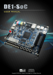
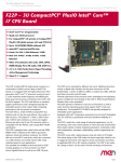
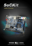
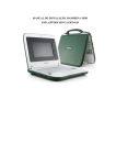
1 CONTENTS CHAPTER 1 ABOUT THIS GUIDE ................................................................................................................................. 3 CHAPTER 2 SOFTWARE INSTALLATION ................................................................................................................ 4 2.1 INTRODUCTION ........................................................................................................................................................... 4 2.2 INSTALLING QUARTUS II SOFTWARE............................................................................................................................ 4 2.3 INSTALLING THE ALTERA SOC EMBEDDED DESIGN SUITE .......................................................................................... 5 2.4 GETTING THE LATEST SOFTWARES FROM ALTERA WEBSITE ......................................................................................... 9 CHAPTER 3 DEVELOPMENT BOARD SETUP ...................................................................................................... 12 3.1 INTRODUCTION ......................................................................................................................................................... 12 3.2 DEFAULT SWITCH/HEADER SETTINGS ....................................................................................................................... 13 3.3 USB AND POWER CABLES......................................................................................................................................... 15 3.4 POWERING UP THE SOCKIT BOARD........................................................................................................................... 15 CHAPTER 4 PERFORMING AN FPGA SYSTEM TEST ........................................................................................ 16 4.1 INTRODUCTION ......................................................................................................................................................... 16 4.2 INSTALLING THE USB-BLASTER II DRIVER ............................................................................................................... 16 4.3 DOWNLOADING AN FPGA SRAM OBJECTIVE FILE .................................................................................................. 17 CHAPTER 5 RUNNING LINUX ON THE SOCKIT BOARD ................................................................................... 20 5.1 INTRODUCTION ......................................................................................................................................................... 20 5.2 CREATING A MICROSD CARD IMAGE ......................................................................................................................... 20 5.3 SETUP UART TERMINAL ........................................................................................................................................... 21 5.4 RUNNING LINUX ON SOCKIT BOARD ........................................................................................................................ 23 ADDITIONAL INFORMATION ....................................................................................................................................... 25 2 Chapter 1 About this Guide The SoCKit Getting Started Guide contains a quick overview of the hardware and software setup including step-by-step procedures from installing the necessary software tools to using the SoCKit board. The main topics that this guide covers are listed below: Software Installation: Installing Quartus II and SoC EDS Development Board Setup: Powering on the SoCKit Perform FPGA System Test: Downloading an FPGA SRAM Objective File (.sof) Running Linux on SoCKit Board 3 Chapter 2 Software Installation 2.1 Introduction This section explains how to install the following software: Altera Quartus II software ARM DS-5 Altera Edition Toolkit Getting the latest Softwares from Altera website Note: 64-bit OS required 2.2 Installing Quar tus II software The Altera Complete Design Suite provides the necessary tools used for developing hardware and software solutions for Altera FPGAs. The Quartus II software is the primary FPGA development tool used to create reference designs along with the Nios II soft-core embedded processor integrated development environment, which are both included in the package DVD. Install the following software accompanied from the DVD or download the software from the Altera webpage: www.altera.com/download The kit contents contain a Quartus II CD with a Subscription Edition and Web Edition. The Web Edition of Quartus II does not require a license. The figure below shows the CD. 4 The Web Edition of Quartus II supports developing and programming the Cyclone V SX device on the SoCKit. If you choose to install the Subscription Edition, please note that a purchased license will be required. Please go to the following link for more information on the Subscription Edition: http://www.altera.com/products/software/quartus-ii/subscription-edition/qts-se-index.html 2.3 Installing the Altera SoC Embedded Design Suite The Altera SoC Embedded Design Suite (EDS) contains development tools, utility programs, run-time software, and application examples to enable embedded development on the Altera SoC hardware platform. User can use the Altera SoC EDS to develop firmware and application software. Install the software accompanied from the DVD or download the software from the Altera webpage: https://www.altera.com/download/software/soc-eds After you have installed the SoC Embedded Design Suite (EDS), you can start the ARM® Development Studio 5 (DS-5TM) Altera Edition software. If this is your first time using the DS-5, a popup dialog will automatically ask if you wish to open the license manager. 5 For the free SoC EDS Web Edition, you will be able to use the DS-5 Altera Edition perpetually to debug Linux applications over an Ethernet connection. If you have purchased the SoC EDS Subscription Edition, you would have received an ARM license serial number. Or you can obtain a 30-day evaluation license. The following steps show how to obtain a web edition license or a 30-day evaluation license for subscription edition. Obtain a Web Edition license or a 30-day evaluation license for Subscription Edition Clicking the activation code link on the same download page under the heading Web Edition or 30-Day Evaluation. https://www.altera.com/download/software/soc-eds You will be provided with an activation code. Use this code when prompted by the ARM licensing manager. Launch DS-5. Start --> All Programs --> ARM DS-5 --> Eclipse for DS-5 A Workspace Launcher window will ask you to select a workspace. Press OK to select the default You will see a "No Licenses Found" Window. Select Open License Manager 6 Press the Add License Button in the ARM License Manager and Enter the activation code that you received earlier. Press the Next Button. Use the pull down menu to select a host ID. Press the Next button. 7 Enter your ARM account email address and password. If you do not have an account then click on the link to create one. Press the Finish button. 8 A web edition license or 30-day evaluation license for subscription edition had successfully installed. 2.4 Getting the latest Softwares from Altera website User can download the latest software from https://www.altera.com/download/dnl-index.jsp Select the latest software version for Subscription Edition or web Edition 9 Login to myAltera account. Use your existing login, or get one-time Access. Download files from subscription or web edition page. 10 11 Chapter 3 Development Board Setup 3.1 Introduction The instructions in this section explain how to setup the SoCKit development board. The following pictures show the board overview of SoCKit board. HPS FPGA System Ethernet 10/100/1000 VGA USB 2.0 OTG 24-bit DAC Port Port JTAG USB Blaster II USB-UART Header Port Port VGA OUT DB-15 Connector Line In Mic In Line Out Bottom Side Components: *QSPI Flash 128MB *Micro SD Card Socket *FPGA Configuration Mode Switch USB-UART Controller JTAG Switch 12V DC Power Supply Connector Audio Codec Altera USB Blaster II Controller Chip FPGA DDR3 1GB Power ON/OFF Switch EPCQ 256Mb USB OTG Controller (ULPI) HSMC Connector TSE PHY LTC Connector Altera 28-nm Cyclone V FPGA with ARM Cortex-A9 HPS DDR3 1GB CLKSEL Jumper BOOTSEL Jumper 128x64 Dots LCD Temperature Sensor G-Sensor Clock Circuit for FPGA and HPS IR Receiver LCD Backlight Jumper HPS System Reset Keys HPS User Keys HPS User FPGA User FPGA User Keys Switches Switches HPS User FPGA User FPGA Reset Key LEDs LEDs Figure 3-1 Board Top Overview 12 HSMC Voltage-Level Jumper Figure 3-2 Board Bottom Overview 3.2 Default Switch/Header settings This section describes the default settings of switches and headers on the SoCKit board. Please check the switches and set to positions describe below before moving on. BOOTSEL [2:0] = 100 represents HPS will boot from a 1.8V SD/MMC Flash memory device. Refer to Chapter 3 of SoCKit User manual for details. Table 3-1 HPS BOOTSEL and CLKSEL Setting Headers Board Reference Signal Name J17 BOOTSEL0 J19 BOOTSEL1 J18 BOOTSEL2 J15 CLKSEL0 J16 CLKSEL1 Setting Default Short Pin 1 and 2: Logic 1 Short Pin 2 and 3: Logic 0 Short Pin 1 and 2: Logic 1 Short Pin 2 and 3: Logic 0 Short Pin 1 and 2: Logic 1 Short Pin 2 and 3: Logic 0 Short Pin 1 and 2: Logic 1 Short Pin 2 and 3: Logic 0 Short Pin 1 and 2: Logic 1 Short Pin 2 and 3: Logic 0 13 Short Pin 1 and 2 Short Pin 2 and 3 Short Pin 1 and 2 Short Pin 2 and 3 Short Pin 2 and 3 Table 3-2 SW4 JTAG Control DIP Switch Board Reference Signal Name Description SW4.1 JTAG_HSMC_EN SW4.2 JTAG_HPS_EN On: Bypass HSMC Off: HSMC In-chain On: Bypass HPS Off: HPS In-chain Figure 3-3 BOOTSEL and CLKSEL Figure 3-4 JTAG_EN 14 Default On On 3.3 USB and Power Cables Cable connections are shown in Figure 3-5 as below: Figure 3-5 USB and Power Cables 3.4 Powering up the SoCKit Board To power-up the board, perform the following steps below: 1. Connect the provided power cord to the power supply and plug the cord into a power outlet (verify the voltage supplied is the same as the specification on the power supply). 2. Connect the supplied SoCKit power adapter to the power connector (J12) on the SoCKit board. Press the power button (SW5). At this point, you should see the 12V indicator LED (D5) turn on. 15 Chapter 4 Performing an FPGA System Test 4.1 Introduction This chapter shows how to install the USB-Blaster II driver and download an FPGA SRAM Objective (.sof) file to your FPGA board. 4.2 Installing the USB-Blaster II Driver The steps below outline how to install the USB-Blaster II driver. 1. Connect your computer to the development board by plugging the USB cable into the USB connector (J2) of SoCKit (connection shown in Figure 3-5) 2. Power up the board and open the device manager in Windows. You will find an unknown device. 3. Select the unknown device to update the driver software. The driver file is in the \<Quartus II installation directory>\drivers\ usb-blaster-ii directory. 4. After the driver installed correctly, the device is recognized as Altera USB-Blaster II as shown in following picture. 16 4.3 Downloading an FPGA SRAM Objective File The Quartus II Programmer is used to configure the FPGA with a specific .sof file. Before configuring the FPGA, ensure that the Quartus II software and the USB-Blaster II driver are installed on the host computer. If users would like to program their SRAM Object File (.sof) into the Cyclone V SOC FPGA device on the SoCKit board, execute the following steps: 1. Connect your computer to the SoCKit board by plugging the USB cable into the USB connector (J2) of SoCKit and power up the board (details shown in Chapter 3) 2. Open the Quartus II software and select Tools > Programmer. The Programmer window will appear. 17 3. 4. Click Hardware Setup. If USB-Blaster [USB-1] does not appear under Currently Selected Hardware, select that option and click Close shown below. If the USB-Blaster II does not appear under hardware options list, please confirm if the USB-Blaster II driver has been correctly installed, and the USB cable has been properly connected between the SoCKit board and host computer. 18 5. Click Add File to select the .sof file and click Open. 6. Select \<CD directory>\Demonstration\my_first_fpga\my_first_fpga.sof. 7. Turn on the Program/Configure option that corresponds to the .sof file and click Start, which will automatically download the file into the SoCKit board shown below. 8. After the downloading has been complete, you should be able to find that FPGA_LEDs flashing, meaning that the .sof has been programmed successfully. 19 Chapter 5 Running Linux on the SoCKit board 5.1 Introduction This chapter demonstrates you how to create a microSD card image, set up a UART Terminal, and run Linux on SoCKit Board. 5.2 Creating a microSD Card Image To program a microSD card Linux image you can use a free tool called Win32DiskImager.exe from http://sourceforge.net/projects/win32diskimager/ on a Windows machine. Win32DiskImager can also be found in \<CD directory>\Tools\ Win32DiskImager. microSD Specification Capacity: 4GB minimum Speed: Class 4 Pre-built SD Card Image The pre-built binaries are delivered as an archive named SoCKit_SD.img. This SD card image file contains all the items that are needed to run Linux on SoCKit board. (You can find this file in \<CD directory>\Tools\Factory_SD_image\SoCKit_SD.rar, and extract file to get the image file) SPL Pre-loader U-boot Device Tree Blob Linux Kernel Linux Root File system 20 The SD card image file needs to be programmed to a microSD card before it can be used. The steps below present how to create microSD card on a windows machine using Win32DiskImager.exe. 1. Connect the microSD card to a Windows PC 2. Execute Win32DiskImager.exe 3. Select the image file for microSD card 4. Select the microSD card device 5. Click write to start writing the image file to the microSD card. Wait until the image is written successfully. 5.3 Setup UART Ter minal This section presents how to install the drivers for the USB to UART chip on the SoCKit board and set up the UART terminal on your host PC. The SoCKit board communicates with the PC through the micro USB connector J4.You should install the USB to UART driver and configure the UART terminal before you run Linux on the board. Installing the Driver This section presents how to install the drivers for USB to UART communication. The necessary steps on Windows 7 are: 1. Connect your computer to the development board by plugging the USB cable into the micro USB connector (J4) of SoCKit (connection shown in Figure 3-5) 2. Power on the board then open the computer device manager in Windows. You will find an unrecognized USB Serial Port. 21 Select the USB Serial Port to update the driver software. The driver can be downloaded from http://www.ftdichip.com/Drivers/VCP.htm. or found in \<CD directory>\Tools\ USB2UART_driver. 3. After the driver has installed correctly, the USB Serial Port is recognized as a port such as COM12 (Open the device manager to know which COM port assigned in your computer) 4. Now you can power off the SoCKit board Configure UART terminal UART terminal spec: 57600 baud rate no parity 1 stop bit no flow control settings The following steps present how to configure a PuTTY terminal window (can be found in \<CD directory>\Tools\SSH.) 1. Open putty.exe, click Serial go to a serial configure interface. 2. Configure the window like the flowing picture and click save button to save the configuration. 22 5.4 Running Linux on SoCKit board This section presents how to run the pre-built Linux images on the SoCKit board. You can run the Linux by following the steps below: 1. Insert the microSD card with the pre-built image into the board (See 5.2 to prepare a microSD card) 2. Press down the SW5 button to Power up the board (See Chapter 3 for details) 3. Open putty.exe, select the saved configuration SoCKit_usb and click open button. 4. After a successful boot, the HPS LEDs will blink several times, and Linux will ask for the login name. Type root and press Enter to login to the system. 23 24 Additional Information Getting Help Here are the addresses where you can get help if you encounter problems: Terasic Technologies 9F., No.176, Sec.2, Gongdao 5th Rd, East Dist, Hsinchu City, 30070. Taiwan, 30070 Email: [email protected] Web: www.terasic.com Revision History Date Version Changes 2013.04 V1.0 First Version 25