1
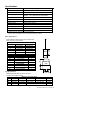
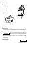
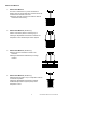
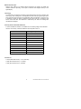
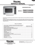
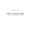
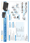
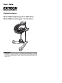
User's Guide
Digital Viscotesters
Model 345060 High Range (0.3 to 4000 dPas)
Model 345055 Low Range (1.5 to 330 mPas)
Introduction
Congratulations on your purchase of the Extech Digital Viscotester. The Extech
Viscotesters are rotational viscometers with a digital display specially suited for fast tests
and comparative measurements on liquids. Careful use of this meter will provide years of
reliable service.
Specifications
Display
Drive
Rotational Drive Speed
Measuring Range
Accuracy
Repeatability
Sample Temperature
Sample Volume
Power
Operating Temperature
Rotor Dimensions
Weight
Multifunction Digital Display
4V rated DC Servo Motor
62.5 RPM
345055 1.5 to 330 mPas (1.5 to 330cP)
345060 0.3 to 4000 dPas (30 to 400,000cP)
± 5% of full scale †
±1% ‡
300οF (150οC) maximum
approx. 5.3oz (150 ml)
Four (4) 1.5V ‘AA’ batteries
50 to 104οF (10 to 40οC)
Refer to the Rotor Specifications section
Case and accessories: 4.4 lbs (2 kg)
† Published accuracy assumes the use of supplied rotors
‡ For two consecutive measurements under identical measuring conditions
Rotor Specifications
Rotor Material: Anodized aluminum or stainless steel
Rotor Accuracy: ±3% Full Scale
Rotor Dimensions
Rotor No.
D
h
1
0.94” (24.0mm)
2.08” (53.0mm)
2
0.59” (15.0mm)
0.04” (1.00mm)
3
1.77” (45.1mm)
1.85” (47.0mm)
4
3.07” (78.0mm)
1.81” (46.0mm)
5
2.40” (61.2mm)
1.41” (36.0mm)
Display
R4
R5
R3
R3
R1
R2
Rotor Measurement Ranges
Model 345055
Rotor
1.5 to 33mPas
4
15 to 150 mPas
5
50 to 330 mPas
3
Model 345060
0.3 to 13dPas
3
3 to 150 dPas
1
100 to 4000dPas
2
Rotor
h
D
h2
Measuring
CUP
h1
Di
Cup Specifications
Material: Stainless steel or anodized aluminum
Sample volume: approx. 400ml
Measuring Cup Dimensions
Type
D
Di
h1
h2
A
3.54”(90mm)
n/a
2.97”(75.5mm)
3.75”(95.5mm)
B
3.54”(90mm)
1.18”(30mm)
2.97”(75.5mm)
3.75” (95.5mm)
3
2.07”(52.6mm)
n/a
2.95”(75mm) (h1+h2)
2
D
Model
345055
345055
345060
Model 345055 & 345060 Version 4.0 December 2005
Description
1.
Function button
2.
Digital display
1
3.
Stand clamp
4.
Rotor
5.
Support stand (optional)
6.
Point of orientation
7.
Battery compartment screw
8.
Battery container
9.
Stand mounts
2
3
4
10. Clamps for Cups A & B (345055)
11. Drive shaft
5
6
9
7
10
8
9
10
11
Operation
Powering the meter
Firmly press and hold the function button until the model number appears on the display
(VT1 for the 345055, VT2 for the 345060).The model number will switch off and the zero
adjust display will appear.
Zero Adjustment
When the zero adjustment display appears the user has 3
seconds to press the function button to activate the automatic
zero adjustment. Press the button again when the model
number appears on the display. The zero adjustment will now run (approx. 13 second test
time during which the display will show ‘CAL WAIT’). The zero adjustment eliminates
display offset. The adjustment is made with the device in the measurement position without
a rotor connected. To skip the adjustment, wait 3 seconds and the ‘MEASUREMENT’
display will appear.
ZERO ADJUST?
Measurement Display
When ‘MEASUREMENT’ appears the unit is ready to measure.
3
MEASUREMENT
Model 345055 & 345060 Version 4.0 December 2005
Viscosity Measurements
1. Press the function button to start measuring. The meter powers up in the range that
was in use when the instrument was last turned off. The motor turns continuously while
measuring.
2. Select the rotor type by briefly pressing the function button (while in the measurement
mode) and selecting another rotor type (Model 345055: R3, R4, R5 and
Model 345060: R1, R2, R3). The display ‘RX wait’ will appear for
approx. 3 seconds and the measurements will be made using the
newly selected rotor measurement range (always verify that the
connected rotor matches the type selected on display). The
rotor type is displayed on the left side of the display; the
viscosity measurement is displayed on the right.
3. Select one of the four measurement methods outlined in the
section ‘Measurement Methods’ later in this manual.
4. Suspend the rotor and, if required, connect the measuring cup
to the clamps.
5. Immerse the rotor into the test substance up to the dip mark (on the rotor shaft).
6. Hold the unit horizontally by hand or with the optional stand (use of the optional stand
is recommended). If held by hand, hold the unit with the forefinger at the point of
orientation (see diagram).
7. Read the measured value on the display. The value on the left side of the display
represents the rotor type (R1 to R5). The value on right is the viscosity measurement.
By pressing the function button momentarily (1 second) the motor shuts off and the last
measured value calculated for the viscosity will be ‘’frozen’’. By pressing the function
button again the measurement will be restarted in the range last used.
Turning the meter OFF
From the measurement mode, firmly press and hold the function
button for approx. 3 seconds to turn the instrument off. The
display will then alert the user as to the number of hours (h)
remaining before a calibration (service) is due. The display will then switch off.
SERVICE IN 300h
Error Message Displays
RX
XX! dPas
Minimum measuring range exceeded; use a larger rotor.
RX
>XX dPas
Maximum measuring range exceeded; use a smaller rotor.
SAFETY CUT OFF
OVERLOAD
Maximum range exceeded for 5 subsequent measurements.
The error message appears and the motor stops.
The electrical current limitation has been reached. The unit
automatically switches off. Have the unit serviced.
4
Model 345055 & 345060 Version 4.0 December 2005
Measurement Methods
1.
Measurement Method 1
The Rotor is immersed in any vessel. The distance
between the rotor and the wall of the vessel should not be
smaller than the diameter of the rotor.
Advantages: Ideal for comparing test solutions. Ease of
measurement and cleaning.
Method 1
2.
Measurement Method 2 (345055 only)
Solution under test is placed in measuring Cup A.
Advantages: Repeatable measurement conditions and
temperature control. Small sample volume required.
Method 2
3.
Measurement Method 3 (345055 only)
Measuring Cup B is immersed in solution to be
measured.
Advantage: Measurement made directly in storage
container.
Method 3
4.
Measurement Method 4 (345060 only)
Measurements are made in Cup 3. Temperature control in
circular bath is possible.
Advantages: Repeatable measurement conditions.
Smallest sample solution required (150ml). Exact
temperature control.
Method 4
5
Model 345055 & 345060 Version 4.0 December 2005
Measurement Principle
With the rotor rotating at a constant speed, immersed in the liquid to be tested, the
rotational resistance (viscosity) of the liquid is measured and displayed directly on the
digital display.
Technology
The drive axis is connected to one side of a spiral spring and the rotor axis to the other end
of the spring. When rotating with no load applied, the ends of the spring pass a light sensor
at the same time (since the spring is not deflected). With a load applied, i.e. when the rotor
is immersed in liquid, the spring is twisted and the spring ends do not break the light
sensor at the same time. The difference is measured by the meter and readings are
calculated and displayed.
Viscosity Values of Selected Substances
In order to facilitate the selection of a suitable rotor, the following table contains standard
o
values for the viscosity of selected substances at a temperature of 20 C.
Substance
Viscosity [mPas]
Water
1†
Sucrose solution
6 (40g in 100 ml Water)
Coffee cream
10
Light crude oil
10
Glycol
20
Olive oil
84
Lubricant oil 300 bis
800
Lubricant oil 50 bis
1,000
Rhizinus oil
1,500
Honey
10,000
Bitumen
100,000,000†
† Beyond the measuring range of the Models 345055 & 345060
Conversions
1 mPas (milli Pascal second) = 1 cP (centi Poise)
1 dPas (deci Pascal second) = 1 P (Poise)
1 dPas (deci Pascal second) = 100 mPas
6
Model 345055 & 345060 Version 4.0 December 2005
Temperature Influence on Viscosity
Viscosity is temperature dependant and, therefore, the temperature of the test material
should be controlled. The temperature should be recorded for each viscosity
o
o
measurement, e.g. 26.3 C = 160 mPas (i.e.: the viscosity at 26.3 C is 160 milli
Pascalseconds). It is possible to determine the viscosity dependence on temperature by
performing viscosity measurements at two different temperatures and calculating the
corresponding viscosity value in relation to the reference temperature.
Example
o
For example, at 18 C a measurement is taken and the reading is 200 mPas. Another
o
o
reading is taken at 24 C and the reading is 170 mPas. This 6 change in temperature
o
(24 – 18 = 6 C) corresponds to a change in viscosity of 30mPas (200 – 170 = 30 mPas).
In this case, the viscosity changes 5mPas for each degree (refer to the table below).
Note: 20οC is used as the reference temperature for instrument calibration.
Temperature (οC)
Viscosity (mPa seconds)
18
200
20
190
22
180
24
170
26
160
28
150
Comparing Viscometer Readings
Test results of purely viscous (Newtonian) liquids (e.g. mineral oils, sugar solutions,
glycerine) obtained with a viscotester can be compared directly with the results of other
viscometers. Most liquids, however, have a different viscosity measurement under differing
shearing conditions (size and design of the rotors, the rotor speed, etc). For this reason,
test results of non–Newtonian liquids obtained by two different types of viscometers are
usually not comparable. A viscometer with variable shearing conditions is required to
perform such comparisons. Note that Models 345055 and 345060 do not have a variable
shearing function.
Verification of the Viscotester
In order to verify the functionality of the viscotester, tests on Newtonian liquids should be
performed regularly. For this, a standard liquid corresponding to the measuring range of
the rotor must be used. The measurement must be made in the original measuring cup
that was supplied with the standard. The value which is displayed on the viscotester must
correspond to the value indicated on the provided certificate for the standard liquid within
the specified tolerance (accuracy of the measuring system + accuracy for the certified
viscosity). Since viscosity depends largely on temperature, the measurement must be
made at the temperature indicated for the viscosity of the standard liquid.
7
Model 345055 & 345060 Version 4.0 December 2005
Battery Replacement
Change Batteries
If the viscotester does not turn on or if the ‘Change Batteries’
display appears, the four (4) 1.5V ‘AA’ batteries must be
replaced.
1. Unlock the battery compartment by backing off the compartment locking screw
approximately ½ turn.
2. Once the compartment is unlocked, carefully pry off the compartment cover.
3. Replace the ‘AA’ batteries observing polarity.
4. Re-attach the compartment cover and tighten the locking screw.
Calibration and Repair Services
CAL RECOMMENDED
If the ‘CAL RECOMMENDED’ display appears, the unit must
be returned for calibration or other servicing.
Extech offers repair and calibration services for the products we sell. Extech also provides
NIST certification for most products. Call the Customer Service Department for information
on calibration services available for this product. Extech recommends that annual
calibrations be performed to verify meter performance and accuracy.
Warranty
EXTECH INSTRUMENTS CORPORATION warrants this instrument to be free of defects in parts and
workmanship for one year from date of shipment (a six month limited warranty applies on sensors and
cables). If it should become necessary to return the instrument for service during or beyond the warranty
period, contact the Customer Service Department at (781) 890-7440 ext. 210 for authorization or visit our
website at www.extech.com (click on ‘Contact Extech’ and go to ‘Service Department’ to request an RA
number). A Return Authorization (RA) number must be issued before any product is returned to Extech. The
sender is responsible for shipping charges, freight, insurance and proper packaging to prevent damage in
transit. This warranty does not apply to defects resulting from action of the user such as misuse, improper
wiring, operation outside of specification, improper maintenance or repair, or unauthorized modification.
Extech specifically disclaims any implied warranties or merchantability or fitness for a specific purpose and
will not be liable for any direct, indirect, incidental or consequential damages. Extech's total liability is limited
to repair or replacement of the product. The warranty set forth above is inclusive and no other warranty,
whether written or oral, is expressed or implied.
Support Hotline (781) 890-7440
Tech support: Ext. 200; Email: [email protected]
Repair/Returns: Ext. 210; Email: [email protected]
Website: www.extech.com
Copyright © 2005 Extech Instruments Corporation
All rights reserved including the right of reproduction in whole or in part in any form.
8
Model 345055 & 345060 Version 4.0 December 2005