1
There are two types of limits, Absolute and Relative. The LDM bit in the CMM register
establishes which type will be used, where “0” indicates Absolute and “1” indicates
Relative. In Absolute Alarm Mode, the limits are fixed and do not change, while in
Relative Alarm Mode the limits change whenever the current Alarm Limits are exceeded.
As the name suggests, Absolute Alarm Mode is used for monitoring the absolute
magnetic field, while Relative Alarm Mode is used to monitor changes in magnetic field.
Absolute Alarm Mode
In Absolute Alarm Mode the limits are set for each axis by the Alarm Lower Limit
and Alarm Upper Limit registers, as given in Table 5-5. The register values are
unsigned integers. The ALARM bit will go HIGH if the measured value (MX, MY,
or MZ) on any given axis is either greater than the Alarm Upper Limit for that axis or
less than the Alarm Lower Limit for that axis. This is an “OR” function, looking at
both the Alarm Upper and Lower Limits, and looking at all sensors being measured.
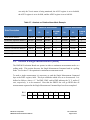
Table 5-5: Alarm Lower and Upper Limit Registers
Register
Name
Read
(Hex)
Write
(Hex)
X Axis Alarm Lower Limit - MSB
ALLX2
8C
0C
X Axis Alarm Lower Limit - mid
ALLX1
8D
0D
X Axis Alarm Lower Limit - LSB
ALLX0
8E
0E
X Axis Alarm Upper Limit - MSB
AULX2
8F
0F
X Axis Alarm Upper Limit - mid
AULX1
90
10
X Axis Alarm Upper Limit - LSB
AULX0
91
11
Y Axis Alarm Lower Limit - MSB
ALLY2
92
12
Y Axis Alarm Lower Limit - mid
ALLY1
93
13
Y Axis Alarm Lower Limit - LSB
ALLY0
94
14
Y Axis Alarm Upper Limit - MSB
AULY2
95
15
Y Axis Alarm Upper Limit - mid
AULY1
96
16
Y Axis Alarm Upper Limit - LSB
AULY0
97
17
Z Axis Alarm Lower Limit - MSB
ALLZ2
98
18
Z Axis Alarm Lower Limit - mid
ALLZ1
99
19
Z Axis Alarm Lower Limit - LSB
ALLZ0
9A
1A
Z Axis Alarm Upper Limit - MSB
AULZ2
9B
1B
Z Axis Alarm Upper Limit - mid
AULZ1
9C
1C
Z Axis Alarm Upper Limit - LSB
AULZ0
9D
1D
Register Description
PNI Sensor Corporation
RM3100 Evaluation Board User Manual
Doc 1017252 r02
Page 21 of 33