1
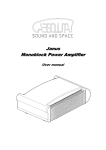
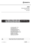
RS605 5 x 60W Slave Amplifier Item ref: 953.151UK User Manual Introduction Thank you for choosing the Adastra RS605 rackmount 5 x 60W slave amplifier as part of your public address system. This amplifier is designed to offer high quality, dependable service for mobile and installed systems. Please read this manual fully and follow the instructions to achieve the best results with your new purchase and to avoid damage through misuse. Caution: Please read this manual carefully before operating Damage caused by misuse is not covered by the warranty SAFETY SYMBOL AND MESSAGE CONVENTIONS CAUTION RISK OF ELECTRIC SHOCK DO NOT OPEN AVIS RISQUE DE CHOC ELECTRIQUE NE PAS OUVRIR This symbol indicates that dangerous voltage constituting a risk of electric shock is present within this unit This symbol indicates that there are important operating and maintenance instructions in the literature accompanying this unit. SAFETY NOTICE 1. Prior to use, read through this manual 2. Keep the manual in good condition 3. 4. 5. 6. 7. 8. 9. 10. 11. 12. 13. 14. 15. 16. 17. Pay attention to safety warnings Observe all operating requirements Do not use the device near water or wet areas For cleaning, only use a lint-free, dry cloth Install according to the specifications Place away from heat sources or heating appliances Use mains lead provided and avoid damage to cable or connectors Unplug power from mains during stormy weather or if unused for long periods In case of malfunction, water ingress or other damage, consult qualified service personnel Do not place in damp areas or near liquids or moisture. Do not spill liquids on the housing Please pay attention to warning symbols during transit and placement Terminals marked with the symbol are HAZARDOUS LIVE and should only be connected by qualified personnel Ensure that the apparatus is connected to a mains socket with a protective EARTH connection Ensure correct operation of the mains switch The DC input terminals must only be connected to a DC power supply which complies with SELV Warning To prevent the risk of fire or electric shock, do not expose any components to rain or moisture. If liquids are spilled on the casing, stop using immediately, allow unit to dry out and have checked by qualified personnel before further use. Avoid impact, extreme pressure or heavy vibration to the case No user serviceable parts inside – Do not open the case – refer all servicing to qualified service personnel. Safety Check for correct mains voltage and condition of IEC lead before connecting to power outlet Use double insulated speaker wire with adequate current rating for 100V speaker connections Do not use 8Ω and 100V terminals at the same time Do not connect 8Ω speakers to the 100V terminal or 100V speakers to the 8Ω terminal Do not allow any foreign objects to enter the case or through the ventilation grilles or CD slot Placement For rack-mounting, ensure adequate support for the weight of the amplifier Ensure adequate air-flow and do not cover cooling vents at the front and rear of the amplifier Ensure adequate access to controls and connections Cleaning Use a soft cloth with a neutral detergent to clean the casing as required Use a vacuum cleaner to clear ventilation grilles of any dust or debris build-ups Do not use strong solvents for cleaning the unit 953.151UK User Manual Front panel 1. PROTECT LED indicators 2. CLIP LED indicators 3. SIGNAL LED indicators 4. Channel volume controls 5. Power on/off switch Rear panel 6. Mains voltage selector 7. IEC mains inlet & fuse holder 8. 24Vdc power connection 9. Mode switch 10. Speaker output modular connectors 11. Channel GAIN controls 12. Line input connectors (RCA) 13. Ventilation grille - do not cover 953.151UK User Manual Connection and setup Connect the rear IEC inlet (7) to the mains using the supplied mains lead (or an equivalent approved type). Ensure that the voltage is correct as indicated on the voltage selector (6) and that the mains outlet is switched on. Alternatively, the RS605 can be powered by a 24V battery, such as a lorry or boat battery, by connecting the “+” and “-” of the battery to the 24Vdc INPUT (8) on the rear panel. Note: Ensure that DC cables are capable of handling the current (15A min. recommended) Ensure the POWER (5) is switched off until all input and speaker connections are in place. The RS605 is designed to accept up to 5 line inputs from a mixer or multiple input sources and provide power for up to 5 independent speaker zones from its 5 internal amplifiers. Line level signal inputs should be connected to the dual RCA INPUT connectors (12) at the rear. Each of the 5 amplifiers are mono, so any stereo input signals will be summed together to provide a monaural output. A Mode switch (9) offers the option of independent input to each amplifier (5CH) or a mix of all inputs to all amplifiers (MIX) Speaker outputs Each of the RS605 amplifiers can be used either as a 100V line amplifier or standard low impedance power amplifier. These 2 configurations cannot be used together, so it is important to decide which method will be used at the start. The RS605 speaker outputs are via modular connectors with screw terminals. These modular connectors may be unplugged from the rear for convenience during installation. Information about the differences between 100V and low impedance systems are detailed on the following pages. 953.151UK User Manual 100V line systems For 100V line systems, connect the amplifier to the first speaker in the system using double-insulated speaker wire which has adequate current rating to handle the total output of the amplifier. Connect the “100V” output terminal to the positive (+) connection of the speaker and “COM” output to the negative (-) connection of the speaker. Connect further speakers in parallel to the first speaker with all positive terminals and connected together and all negative terminals connected together as shown below. A 100V line speaker system can comprise of many speakers connected together. The determining factor for how many speakers can be used on a single amplifier is the power rating. For most purposes, it is advised to connect as many speakers as needed with a combined wattage of no more than 90% of the amplifier’s output power rating. The terminals of a 100V speaker are connected to a transformer and in some cases, this transformer may be “tapped” for different power ratings. These tappings can be used to adjust the wattage (and output volume) of each speaker in the system to help achieve the ideal total power of the system for the amplifier. Low impedance systems Alternatively, each of the RS605 amplifiers can provide an output for a single 8Ω speaker by connecting the “8Ω” output to the positive (+) speaker connection and “COM” output to the negative (-) speaker connection. It is important to ensure that the speaker load is no less than 8Ω and that the power handling of the speaker is equal to or greater than the output power of the amplifier. 953.151UK User Manual Operation Select the required operating mode from the MODE switch on the rear panel (9). If the preferred usage is for all outputs to have the same signal, the MIX mode may be used, allowing 5 inputs to all 5 amplifiers. Otherwise, the 5CH mode feeds each input independently to its relative amplifier. As a start point, set all the GAIN (11) controls on the rear panel to the 12 o’clock position. When all connections to the amplifier are made, turn all channel volume controls (4) fully down and switch on the power (5) and the power LED will illuminate. Ensuring that the signal is active on one of the channel inputs, gradually turn up the relevant volume control until the sound can be heard through the speaker(s). Each amplifier channel has its own SIGNAL LED (3) to indicate the status of the audio input. A CLIP LED (2) indicates when this signal is clipping or overloading. If the CLIP LED lights any more than very briefly during operation, the relevant GAIN control should be reduced. This same GAIN control can be increased if the input signal is not loud enough to drive the channel. This would be the case if the CLIP LED never lights even when the channel volume is at full level. Each amplifier channel also has a PROTECT LED (1) on the front panel to indicate if that amplifier has entered the protect mode. This indicates that the amplifier has experienced a problem and the amplifier should then be switched off and disconnected from the mains. Disconnect the input and speaker output from the protected amplifier channel before attempting to switch on again. If all else is operational, check the speaker and cable and ensure that the input signal works OK on a different channel. Check also that the speaker was connected to the appropriate terminal(s) on the modular connector. If there is still a PROTECT indication after checking and reconnecting inputs and outputs, refer to qualified service personnel to check the amplifier(s) Powering down To avoid loud pops through the speakers, turn down the MASTER control before powering down. 953.151UK User Manual Specifications Power supply 110/230Vac, 50/60Hz DC power 24Vdc screw terminals Fuse T5A (250V) Output power 300Wrms (5 x 60W, all channels driven) Output connections 5 x modular terminals (COM/8 Ohms/100V) Input connections 5 x paired RCA line Input sensitivity -10dBV Frequency response 100Hz-20kHz T.H.D. 1.0% S/N ratio 90dB Controls 5 x volume, 5 x gain (rear), mode switch Dimensions 482 x 89 x 420mm Weight 14kg 953.151UK User Manual Troubleshooting Ensure IEC lead is in good condition and connected properly No power LED on control panel If 24Vdc power input is being used, check battery is charged Ensure POWER switch is on and check mains inlet fuse Check input signals and condition of input connection leads Power LED is on but no other LEDs and no output Check that the correct operation mode has been selected (MIX/5CH) Check that the channel GAIN control is not turned fully down Check that the relevant channel volume control is turned up POWER and SIGNAL LEDs lighting but no output Check speaker output terminals are connected correctly Check speakers are working (test on another amp if available) Check level of input signal is not too high Output is very loud or distorted Reduce channel GAIN control Reduce channel volume control Check input signal level is not too low Output is working but at very low level Increase channel GAIN control Increase channel volume level Ensure cooling vents are clear from debris and dust Check that 8Ω speakers are not connected to 100V terminals Amplifier overheating Ensure total 100V speaker wattage is lower than amplifier rating Ensure that 100V and 8Ω speakers are not both connected together Ensure that total load connected to 8Ω output is not less than 8Ω Disposal: The “Crossed Wheelie Bin” symbol on the product means that the product is classed as Electrical or Electronic equipment and should not be disposed with other household or commercial waste at the end of its useful life. The goods must be disposed of according to your local council guidelines. Errors and omissions excepted. Copyright© 2014. AVSL Group Ltd. 953.151UK User Manual