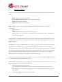
1
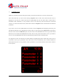
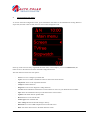
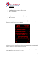
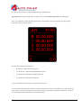
POLAR FIS ADVANCED
USER MANUAL FOR
WHITE/COLOR DOT FIS CLUSTERS
Polar FIS for white/color dot clusters User manual
Sheet: 1 of 25
INDEX
1.
INTRODUCTION____________________________________________________ 3
2.
CONFIGURATION MENU ____________________________________________ 4
2.1.
2.1.1.
SCREEN. _________________________________________________ 5
SCREEN-VISUALIZATION. ______________________________________ 5
2.1.1.1.
SCREEN->VISUALIZATION->PARAMETERS ___________________ 6
2.1.1.1.1 SCREEN->VISUALIZATION->PARAMETERS->SCREEN x ________ 7
2.1.1.2.
SCREEN->VISUALIZATION->ADVANCED _____________________ 8
2.1.1.3.
SCREEN->VISUALIZATION->LANGUAGE ____________________ 10
2.1.2.
SCREEN->POLAR BUTTONS. ___________________________________ 11
2.2.
TVFREE _________________________________________________ 12
2.3.
STOPWATCH ____________________________________________ 13
2.4.
COMFORT. ______________________________________________ 15
2.4.1.
COMFORT->MIRRORS _________________________________________ 16
2.4.2.
COMFORT->TURN SIGNALS. ___________________________________ 18
2.4.3.
COMFORT->PARKTRONIC FIS. _________________________________ 19
2.4.4.
COMFORT->PARKTRONIC FIS. _________________________________ 20
2.5.
BLUETOOTH ____________________________________________ 20
21
3.
NOTES
4.
ANNEX 1: PARAMETER LIST. ________________________________________ 22
Polar FIS for white/color dot clusters User manual
Sheet: 2 of 25
1.
INTRODUCTION
Thanks for purchasing Polar FIS, along this manual you will learn all functions of your new Polar FIS box.
After install Polar FIS, you will see that entering Telephone menu in FIS screen; Polar FIS main screen is
displayed. In case that your vehicle does not have OEM Hands free unit, this menu will be created. Due to
instruments cluster limitations, it is not possible to create a new menu entry like in Polar FIS for red dot FIS
vehicles, so in white/colour FIS vehicles, Polar FIS will share the Telephone menu with the hands free OEM unit
if installed.
If you want to Access to the OEM hands free unit menu, from the Telephone menu displaying Polar FIS, press
and hold the OK button of the multifunction steering wheel or wiper stalk until the Main menu screen appears,
from this screen choose the Bluetooth option, and you will be in the OEM Hands free menu, to go back to Polar
FIS menu, exit as normal from OEM Hands free menu, and you will go back in Polar FIS. At last, if you make or
receive a call, the OEM Hands free menu will automatically prompt as before install Polar FIS.
It is important as well to note that there is another difference regarding Polar FIS in red dot FIS, in that version it
is possible to show up to 6 parameters at the same time in screen, unfortunately, this is another limitation in
white/colour FIS, here it is only possible to show 4 parameters, so you Polar FIS main screen will be similar to
the next picture:
Polar FIS for white/color dot clusters User manual
Sheet: 3 of 25
2.
CONFIGURATION MENU
To Access Polar FIS configuration menu, press and hold the OK button in the multifunction steering Wheel or
wiper stalk, and after a few seconds, the next screen will be displayed in FIS:
In the top of the screen is always signalized the menu name, in this example, you can read Main menu, this
means we are in the main screen of the Polar FIS configuration menu.
The main menu screen has the next options:
-
Screen: Use it to configure your Polar FIS.
-
Tvfree: Access to enable or disable the video in motion activation function.
-
Stopwatch: Access to the stopwatch functions.
-
Comfort: Comfort functions.
-
Diagnosis: Access to the diagnostic coding functions.
-
Version: Shows Hardware and Software version number as well as of your Polar FIS serial number.
-
Info: Show the information about you vehicle Electronic Control Units.
-
Update: Enter Polar FIS into update mode.
-
Reset: Perform a reset of Polar FIS.
-
Switch off: Switch off Polar FIS.
-
Fact. settings: Restore Polar FIS settings to factory.
-
Bluetooth: To Access OEM Telephone menu in the FIS screen.
-
Back: Exit from menu screen to the Polar FIS main screen.
Polar FIS for white/color dot clusters User manual
Sheet: 4 of 25
2.1.
SCREEN.
Inside this screen you can configure the options of Polar FIS, this screen consist in the next options:
-
Visualization.
-
Polar buttons.
Choose the option Visualization to select the parameters that you desire to show in the Polar FIS main screen, as
well as to access advanced configuration or change the Polar FIS menu name.
Choose Polar keys to switch the function of each key while FIS is displaying the Polar FIS screen.
2.1.1.
SCREEN-VISUALIZATION.
In this screen, you will find the next options:
-
Parameters.
-
Advanced.
-
Language.
Choose Parameters to select the parameters that you desire to show in the Polar FIS main screen.
Select Advanced to access advanced configuration of Polar FIS.
Language allows you to select the desire language for Polar FIS.
Polar FIS for white/color dot clusters User manual
Sheet: 5 of 25
2.1.1.1.
SCREEN->VISUALIZATION->PARAMETERS
Inside this menu, you can configure each parameter displayed in each Polar FIS desktop, as well as set the
number of desired desktops.
To a better understanding of it, Polar FIS has from 1 to 10 configurable desktops, each one with a configurable
parameter set, once configured desktop parameters, number of desktops, and a button to switch between them,
you can switch quickly from one desktop to another from the Polar FIS menu using the programmed button.
In the parameters screen, you will have the next options:
-
Screen 1
-
Screen 2
-
Screen….
-
Screen qty.
The number of Screen … options depends on how many desktops you have configured. To configure the desired
number of desktops, enter in Screen qty. and select the desired number of desktops.
To modify the parameter set of one desktop, select the option Screen followed by the number of desktop that you
want to configure, in example, to modify the desktop 1, choose Screen 1.
Polar FIS for white/color dot clusters User manual
Sheet: 6 of 25
2.1.1.1.1 SCREEN->VISUALIZATION->PARAMETERS->SCREEN x
Inside this menu, you can configure the desired parameters to show in the selected desktop.
The next options will be available
-
Parameter 1.
-
Parameter 2.
-
Parameter 3.
-
Parameter 4.
If you want to modify the displayed parameter of one position, simply choose the selected position (parameter 1,
parameter 2, …) and the available parameters list will be displayed to select the desired value.
IMPORTANT INFORMATION:
When a desktop is configured to show 5 parameters, the top parameter cannot be configured and
always be set to vehicle speed, only the other 4 parameters can be configurable.
In some values, the parameter text starts with the ! Character, this means that this is a requested
or calculated value.
Not all parameters are available for all engine ecus, to know which parameters will be available
for your engine ecu, please use that document:
http://www.auto-polar.com/downloads/FIS_ADVANCEDSUPORTED_ECUS.xls
Polar FIS for white/color dot clusters User manual
Sheet: 7 of 25
2.1.1.2.
SCREEN->VISUALIZATION->ADVANCED
From this screen, you can access to the advance characteristics of Polar FIS, the next options are available:
-
Boost options.
-
!Boost options.
-
Oil options.
-
Tank capacity.
-
Press. units.
-
Torque adj..
-
Lambda opt.
-
Screen info.
Boost options: From this screen you can select the desired bus to read the boost pressure, there are 4 options
available:
-
Automatic: Polar FIS will switch the optimal bus to read it.
-
Infort. x1: Polar FIS will use the infortainment bus for read boost pressure.
-
Infort. x2: Polar FIS will use the infortainment bus, but reading will be multiplied by 2.
-
Diagnostic: Reading will be done from the diagnostics bus.
!Boost options: Configures the reading of the engine ecu demanded boost pressure, there are 2 options:
-
Absolute: Reading will not be altered..
-
Relative: Atmospheric pressure will be subtracted from the read value.
Oil options: Configures the bus from which the oil temperature will be read, there are 3 options:
-
Automatic: Polar FIS will switch the optimal bus to read it.
-
Infort x1: Polar FIS will use the infortainment bus for read.
-
Diagnostic: Reading will be done from the diagnostics bus.
Tank capacity: Use it to obtain the best accuracy in the remaining fuel litters parameter. Due to the vehicle does
not indicate readings of more than 52 litters, it is recommended that if your fuel tank exceed of 52 litters, you
configure it.
Prior to make this adjustment, it is requested that fuel tank is full and you know the capacity of it in litters, due to
this will be required in screen.
Press. units: From this screen you can choose the desired units for pressure readings from:
-
Mbar (Millibar).
-
Bar.
-
PSI.
Polar FIS for white/color dot clusters User manual
Sheet: 8 of 25
Torque adj.: Used in engine tuned vehicles in which the torque is rescaled and this results in wrong torque or
power readings in Polar FIS. If you see that your vehicle does not show the maximum torque or power values
indicated by your engine tuner, use that option to introduce your stock and actual (tuned) torque in order to a get
a more exact reading of torque and power.
Lambda opt.: Configure the mode of Lambda value, there are 3 options available:
-
Standard: The value is represented like read from engine ecu.
-
AFR: The value showed is the result of multiply the engine ecu reading by 14,7.
Screen info: Activating it, every time you change the active desktop shown in the Polar FIS main screen, a
message indicating the selected desktop will be shown in screen.
Polar FIS for white/color dot clusters User manual
Sheet: 9 of 25
2.1.1.3.
SCREEN->VISUALIZATION->LANGUAGE
From this screen, you can select the desired language of Polar FIS screen. Before to explain how to configure,
please note that there are 2 Polar FIS firmware versions for white/colour dot FIS, depending on language:
-
-
WZ1: Contains the next languages:
o
English.
o
French.
o
Spanish.
o
Italian.
o
Portuguese.
o
Russian.
WZ2: Contains the next languages:
o
German.
o
Czech.
o
Danish.
o
Romanian.
o
Slovak.
o
Polish.
Once you enter to the language selection screen, you will see first the option Automatic, followed by the
languages available for your firmware version. If Automatic is selected, Polar FIS language will be the same as
configured in the FIS screen. If you choose other option than Automatic, that overrides the FIS language and
switch the Polar FIS language to the selected one.
Polar FIS for white/color dot clusters User manual
Sheet: 10 of 25
2.1.2.
SCREEN->POLAR BUTTONS.
Access to this screen to modify the buttons functions while FIS screen is displaying Polar FIS.
Once you enter in that screen, you will see the list of configurable buttons, select which you desire to configure:
-
Up button.
-
Down button.
-
Ok button.
After select the desired button, a list with all available functions for this button will be displayed:
-
Off: No function for this button.
-
Screen -: Switch desktop -.
-
Screen +: Switch desktop +.
-
Voice control: Voice control.
-
Volume -: Decrease audio volume.
-
Volume +: Increase audio volume.
-
Track -: Previous audio track.
-
Track +: Next audio track.
IMPORTANT INFORMATION:
Due to there are several models and possible coding for Radio/Navigation units, it’s not possible to
guarantee the VOLUME, TRACK and VOICE CONTROL functions will work in all vehicles.
However, it will work in most of the vehicles.
Polar FIS for white/color dot clusters User manual
Sheet: 11 of 25
2.2.
TVFREE
Enable it to activate the video in motion playback.
Please note that if you do not go to play video, it is recommended to have Tvfree disabled, due to what this
function do is disable the messages from the vehicle to the navigation unit indicating the vehicle speed. This
means that it can affect to the navigation accuracy (in low satellite visibility areas)
Due to that reason, every time ignition is switched off, Tvfree option is disabled.
Polar FIS for white/color dot clusters User manual
Sheet: 12 of 25
2.3.
STOPWATCH
From this screen you will access to the available stopwatch modes.
-
Acceleration: To measure time between 2 desired speeds.
-
Lap: To measure lap times.
Acceleration stopwatch: This stopwatch has the next configuration options:
-
Start speed: Introduce here the speed at which stopwatch start.
-
End speed: Introduce here the speed at which stopwatch stops.
-
Start: Start stopwatch.
Once the stopwatch is started, the next screen will be shown, and the stopwatch would not start until the Start
speed is not rebased, if you desire to make measurements from car stopped, choose 0 as Start speed, the
stopwatch will stop once the vehicle reach the End speed.
As you can see in the picture, in the top of the screen, the first 3 parameter of the active desktop are shown, and
in the bottom of screen it is shown the stopwatch time. If you have any button configured for desktop change,
pressing it, desktop will be changed as in the Polar FIS main screen.
If after a measure you want to do another one, it is not necessary to exit from stopwatch screen, simply press and
hold the OK button unit stopwatch time resets to 00.00.000
Polar FIS for white/color dot clusters User manual
Sheet: 13 of 25
To exit from stopwatch screen, press and hold the UP or DOWN button
Lap stopwatch: In this stopwatch mode, the same screen as in Acceleration stopwatch will be displayed:
There is one difference in that stopwatch, pressing up or down button; the screen will switch to the lap time
screen that will be as the next picture
The next data is displayed in that screen.
-
B: 00.00.00 – Indicates the best lap time.
-
L1: 00.00.000 – Indicate the antepenultimate lap time.
-
L2: 00.00.000 – Indicate the penultimate lap time.
-
L3: 00.00.000 – Indicate the last lap time.
At last, in the bottom of the screen, the stopwatch time is shown.
To start the stopwatch, press the OK button, and time will start, after that, every OK button press will mean a lap.
If you want to restart the stopwatch, like in acceleration mode, simply press and hold the OK button, and also to
exit from stopwatch press and hold the UP or DOWN button.
Polar FIS for white/color dot clusters User manual
Sheet: 14 of 25
2.4.
COMFORT.
Inside this screen, you can configure the comfort options of Polar FIS, depending on your vehicle configuration;
the next functions will be available:
-
Mirrors: Configure the automatic mirror dipping function when parking.
-
Blinkers: Configure the number of blinks for comfort turn signals.
-
Parktronic FIS: Enable or disable the Parktronic sensor representation in FIS screen.
Polar FIS for white/color dot clusters User manual
Sheet: 15 of 25
2.4.1.
COMFORT->MIRRORS
Access this screen to configure the automatic mirror dipping function. Inside this screen, you will find the next
options:
-
Mode: Configure the mode of functioning.
-
Position adjust: Configure the mirror Driving and Parking position.
-
Offset: Positioning fine adjustment.
-
Offset mult.: Positioning vast adjustment.
Mode: Inside this screen, you can configure the mode of mirror dipping feature, there are 3 possible
configurations:
-
Off: Deactivated.
-
Manual: Enabled only when mirror switch is in R position.
-
Auto: Available only when manoeuvre is signalized with the passenger side blinker, independently of
the mirror switch position.
In Manual mode, it is required the mirrors switch in R position, in that case, when you engage the reverse gear,
passenger mirror will goes down to Parking position, and when reverse gear is disengaged, mirror will go up to
the Driving position
Automatic mode, is similar to Manual mode, but, to enable it is required to signalize the manoeuvre of parking
with the passenger side blinker, once you signalize with the blinker, the passenger mirror will go down to
Parking position when reverse gear is engaged, and goes up to driving position when reverse gear is disengaged.
This will be done automatically until the vehicle doesn’t exceed 20 Km/h speeds, if you drive above that speed,
Polar FIS will understand that the Parking manoeuvre is finished and you are on the road, and for the next
Parking manoeuvre, you must signalize the manoeuvre with the blinker again.
NOTE: If you have installed Polar FIS in your vehicle, it will be not possible to configure the Mode until you do
not configure the mirror Driving and Parking positions.
Position adjust.: From this option, you can configure the Driving and Parking mirror positions. To do it, enter in
this screen and follow the next steps requested on screen.
-
Select the R position in the mirror switch.
-
Place the passenger mirror into Driving position (this is the mirror position that you use to drive).
-
Place the passenger mirror into the Parking position (this is the desired position when you go to park
your vehicle).
-
Switch desired Mode: The previously described modes.
Polar FIS for white/color dot clusters User manual
Sheet: 16 of 25
Offset: Due to vehicles that has no Factory fitted the automatic mirror dipping feature does not have encoder to
indicate the mirror position, Polar FIS use time base to positioning the mirror. Unfortunately this is not the best
mode for positioning, so this means that in some vehicles after an up and down mirror cycle it does not return to
its original position
If you note that after some up and down mirror cycles mirror goes more and more lower, you must switch a
positive offset value.
If you note that the mirror goes more and more higher, the offset value must be negative.
Unfortunately, there is not an exact value for all vehicles, so the best way is try to modify offset value one by one
and test with some up and down cycles until you find the correct adjustment.
Offset mult.: In the rare case that you have reached the offset maximum value and the mirror still does not reach
the original position, this value must be modified. This value is a multiplier for the offset value, which means,
that in example if you have set the Offset value to 5, and Offset mult. Value to 1, the final offset value will be
5x1 = 5. If you change Offset mult. to 2, the final offset value will be 5x2 = 10.
IMPORTANT INFORMATION:
There is a minimum ecu numbers that are not compatible with the mirror dipping feature which
can result in:
- Automatic mode would not work if R position is not selected in the mirror switch.
- Full malfunctioning of mirror dipping feature.
Polar FIS for white/color dot clusters User manual
Sheet: 17 of 25
2.4.2.
COMFORT->TURN SIGNALS.
From this screen you can select the number of blinks for the Comfort turn signals, the available configuration
values are:
-
3 Blinks.
-
4 Blinks.
-
5 Blinks.
Polar FIS for white/color dot clusters User manual
Sheet: 18 of 25
2.4.3.
COMFORT->PARKTRONIC FIS.
From this screen you can activate or deactivate the function to show the Parktronic sensor measurement in FIS
screen.
With that feature activated, every time you switch on Parktronic and FIS is displaying the Polar FIS main screen,
it will turn to the Parktronic visualization screen which is as follows:
In that screen, are shown all distances expressed in millimetres that are measured by each Parktronic sensor. As
can be seen in the sample picture, the first text line (top) shows the value for left and right front centre sensors.
The next line shows the left and right front sensors. Next line shows left and right rear sensors, and the last one
(bottom) shows the left and right centre rear sensors. In this picture you can see the distance set to 255mm. which
is the maximum value measured by the Parktronic sensors, this means that no obstacles are seen,
Polar FIS for white/color dot clusters User manual
Sheet: 19 of 25
2.4.4.
COMFORT->PARKTRONIC FIS.
From this screen you can activate or deactivate the function to show the Parktronic sensor measurement in FIS
screen.
With that feature activated, every time you switch on Parktronic and FIS is displaying the Polar FIS main screen,
it will turn to the Parktronic visualization screen which is as follows:
In that screen, are shown all distances expressed in millimetres that are measured by each Parktronic sensor. As
can be seen in the sample picture, the first text line (top) shows the value for left and right front centre sensors.
The next line shows the left and right front sensors. Next line shows left and right rear sensors, and the last one
(bottom) shows the left and right centre rear sensors. In this picture you can see the distance set to 255mm. which
is the maximum value measured by the Parktronic sensors, this means that no obstacles are seen,
2.5.
BLUETOOTH
Use that option to access to the OEM Hands free menu in the FIS screen. Once in this screen, if you desire to go
back to the Polar FIS screen, simply exit from OEM hands free menu as usual and you will be again in Polar FIS
screen.
Polar FIS for white/color dot clusters User manual
Sheet: 20 of 25
3.
NOTES
Polar FIS will register itself automatically into the Gateway module, so it is not necessary to do it with any
diagnostics tool.
Due to some parameters are read using diagnostics communication, please do not connect any diagnostics tool or
gauge to the vehicle OBD-II port while FIS screen is displaying Polar FIS menu. In case that you want to use
OBD-II port, please prior to do that exit from Polar FIS screen in example to MFD screen, if you do not do that,
it will resume in communication faults in diagnostics tool as well as in Polar FIS, and a reset can be necessary,
also diagnostics tool will be unable to connect to vehicle.
Due to hardware requisites, Polar FIS is placed between gateway and Infortainment bus, so if you want to
remove Polar FIS from your vehicle, be sure to remove its cable as well, or it can cause battery drainages.
Polar FIS for white/color dot clusters User manual
Sheet: 21 of 25
4.
ANNEX 1: PARAMETER LIST.
TEXT
Km/h
Out. °C
RPM
Batt. V.
Fuel Lit.
!Oil °C
Oil °C
Amb. °C
Intake °C
Coolant °C
Motor °C
Radiat. °C
Fuel °C
!Boost mb
Boost mb
Atm. mb
Intake mb
!Fuel bar
Fuel bar
F. rail bar
Brake bar
Brake b. bar
!Load %
Load %
M.A.F. 1
M.A.F. 2
Pedal 1
Pedal 2
Valve 1
Valve 2
Torq. nm
Power CV
Oil level
M. oil lev.
Inj. tim.
A. °BTDC
Mis.
Mis. 1
Mis. 2
MEANING
Vehicle real speed
Vehicle outside temperature
Engine rpms
Battery voltage
Fuel litters in fuel tank
Calculated engine oil temperature
Measured engine oil temperature
Ambient (engine bay) temperature
Intake temperature
Engine coolant temperature
Coolant temperature at the engine outlet
Coolant temperature at the radiator outlet
Fuel temperature
Requested boost pressure
Measured boost pressure
Atmospheric pressure
Intake manifold pressure
Requested fuel pressure
Measured fuel pressure
Fuel rail pressure
Brake pressure
Brake booster pressure
Calculated engine load
Measured engine load
Mass Air Flow Bank 1
Mass Air Flow Bank 2
Accelerator pedal sensor 1
Accelerator pedal sensor 2
Accelerator valve sensor 1
Accelerator valve sensor 1
Engine actual torque
Engine actual power
Engine oil level in mm. above alarm level
Engine minimum oil level reached in mm. above alarm level
Injection timing
Ignition angle+B52
Misfire sum in all cylinder
Misfire sum cylinder 1
Misfire sum cylinder 2
Polar FIS for white/color dot clusters User manual
Sheet: 22 of 25
TEXT
Mis. 3
Mis. 4
Mis. 5
Mis. 6
Mis. 7
Mis. 8
Mis. 9
Mis. 10
Mis. 11
Mis. 12
D. 1 °KW
D. 2 °KW
D. 3 °KW
D. 4 °KW
D. 5 °KW
D. 6 °KW
D. 7 °KW
D. 8 °KW
D. 9 °KW
D. 10 °KW
D. 11 °KW
D. 12 °KW
Exh. 1 °C
Exh.2 °C
Catal. °C
Lambda 1
Lambda 2
LTFT1-3
LTFT2-4
!N75 %
N75 %
Inj. m/str
St. °BTDC
Dur. °KW
St. q. nm
D.1 m/str
D.2 m/str
D.3 m/str
D.4 m/str
D.5 m/str
D.6 m/str
D.7 m/str
MEANING
Misfire sum cylinder 3
Misfire sum cylinder 4
Misfire sum cylinder 5
Misfire sum cylinder 6
Misfire sum cylinder 7
Misfire sum cylinder 8
Misfire sum cylinder 9
Misfire sum cylinder 10
Misfire sum cylinder 11
Misfire sum cylinder 12
Angle delay cylinder 1
Angle delay cylinder 2
Angle delay cylinder 3
Angle delay cylinder 4
Angle delay cylinder 5
Angle delay cylinder 6
Angle delay cylinder 7
Angle delay cylinder 8
Angle delay cylinder 9
Angle delay cylinder 10
Angle delay cylinder 11
Angle delay cylinder 12
Exhaust gas temperature bank 1
Exhaust gas temperature bank 2
Catalyst temperature
Lambda factor bank 1
Lambda factor bank 2
Fuel trim bank 1
Fuel trim bank 2
Requested N75 valve duty cycle
Measured N75 valve duty cycle
Injection quantity
Injection start
Injection duration
Injection Start quantity
Injection quantity cylinder 1
Injection quantity cylinder 2
Injection quantity cylinder 3
Injection quantity cylinder 4
Injection quantity cylinder 5
Injection quantity cylinder 6
Injection quantity cylinder 7
Polar FIS for white/color dot clusters User manual
Sheet: 23 of 25
TEXT
D.8 m/str
D.9 m/str
D.10 m/str
D.11 m/str
D.12 m/str
EGR1m/str
EGR2m/str
!Control %
Control %
EGT °C
DPF1 °C
DPF2 °C
DPF1 Ash L.
DPF2 Ash L.
DPF %
Regen.
DPF in °C
DPF out °C
Side G
DPF Km.
AdB tank
AdB used
!F. rail bar
!Dur. °KW
!St. °BTDC
!Lambda
!DPF g.
DPF status
DPF mb
Lambda I 1
Lambda I 2
Lambda P 1
Lambda P 2
!Torq. nm
Torque DSG nm
Torque red.
EGT S1 °C
EGT S2 °C
EGT S3 °C
EGT S4 °C
Gen. load
Alt. power W
MEANING
Injection quantity cylinder 8
Injection quantity cylinder 9
Injection quantity cylinder 10
Injection quantity cylinder 11
Injection quantity cylinder 12
EGR valve duty cycle bank 1
EGR valve duty cycle bank 2
Requested charge pressure control
Measured charge pressure control
Exhaust gas temperature
Diesel particle filter temperature bank 1
Diesel particle filter temperature bank 2
Diesel particle filter oil ash volume bank 1
Diesel particle filter oil ash volume bank 2
Diesel particle filter filling level
Diesel particle filer regeneration counter
Diesel particle filter input temperature
Diesel particle filter output temperature
Vehicle side G force
Distance driven since last DPF regeneration
AD-BLUE Filling level
AD-BLUE grams used
Requested fuel rail pressure
Requested injection duration
Requested injection start
Calculated lambda factor
calculated DPF filling
DPF regeneration status
DPF differential pressure
Lambda adaptation at idle bank 1
Lambda adaptation at idle bank 2
Lambda adaptation partial bank 1
Lambda adaptation partial bank 2
calculated engine actual torque
DSG torque reduction
Torque reduction
Exhaust gas temperature sensor 1
Exhaust gas temperature sensor 2
Exhaust gas temperature sensor 3
Exhaust gas temperature sensor 4
Generator load
Alternator power
Polar FIS for white/color dot clusters User manual
Sheet: 24 of 25
TEXT
HVAC nm
HVAC bar
Long. G
MEANING
HVAC compressor torque
HVAC compressor pressure
Vehicle longitudinal G force
Polar FIS for white/color dot clusters User manual
Sheet: 25 of 25
Polar FIS for white/color dot clusters User manual
Sheet: 26 of 25


![[PF03] User manual for RED DOT CLUSTERS(EN) - Auto](http://vs1.manualzilla.com/store/data/005713867_1-90b7ac4617a5dc924635c3e0ee039806-150x150.png)

![[PF03] User manual for WHITE-COLOR DOT - Auto](http://vs1.manualzilla.com/store/data/006282387_1-d7d2ed898b52dfe4f67339814a689f58-150x150.png)