1
Software Tools .MAP .MAP110 User Manual Date: 04.12.2014 File name: D000011475 dotMAP110 User Manual en.docx © Landis+Gyr D000011475 en v 2/134 Revision history Revision history Version Date Comments a 28.02.2005 First edition b 31.05.2005 Changes to release 1.1 c 22.09.2005 Changes to release 1.2 d 05.12.2006 Changes to release 2.2 e 14.12.2006 Field strength indication for GSM installation support changed f 14.01.2010 Changes to release 3.3 New document number D000011475 replaces H 71 0200 0332 (version index continued) g 29.01.2009 Changes to release 3.4 h 06.03.2010 Sections 1 "Overview" and 2 "Installation" updated. All communication surveys new with photos. All communication screenshots adapted to changed software. Designation "meter" generally replaced with "device". Section 5.8 "Command Tree" expanded with user command tree. Section 7.2.5 "Generating Export Files for MAP100" new. Section 7.3.2 "Firmware Update AD-xP/xG" new. Section 7.5.6 "Setting MAP100 File Export" new. Section 7.5.7 "Checking for Updates" new. Section 10 "Short Description of Device Security System" updated Several minor changes (text, layout, screenshots, index). k 20.12.2010 Changes to .MAP110 release 4.0 m 12.01.2011 Adaptation to tool changes: progress bar no longer in status bar, command tree command name changes, several minor changes (text, layout, screenshots). n 30.05.2011 Changes to .MAP110 release 4.1 p 02.11.2011 Changes to .MAP110 release 4.2 q 02.03.2012 Changes to .MAP110 release 4.3 r 21.05.2012 Changes to .MAP110 release 4.4; New Licensing. s 12.10.2012 Changes to .MAP110 release 4.5; New command tree structure with generic and device specific commands; Time base selection for profile readout for devices supporting this feature. t 22.11.2013 Changes to .MAP110 release 4.8; Support for Windows 8, command used is shown in result window, check for update can be called up from "About" window. Several minor changes (text, figures, screenshots, index). u 31.01.2014 Windows XP screenshots replaced by Windows 7 screenshots. Section 6.4.4 "Network connection via the Internet" and section 7.4.5 "Load profile analysis" removed. v 04.12.2014 Changes to .MAP110 release 5.0 (see also read-me file); Communication with message security and additional access mechanisms (authentication), individual passwords and keys per device, enhanced storage policy for keys and passwords, enhanced character set for passwords. Nothing in this document shall be construed as a representation or guarantee in respect of the performance, quality or durability of the specified product. Landis+Gyr accepts no liability whatsoever in respect of the specified product under or in relation to this document. Subject to change without notice. © Landis+Gyr D000011475 en v – .MAP110 – User Manual Introduction 3/134 Introduction Scope The present user manual is designed for the Landis+Gyr .MAP110 Service Tool Version 5.0 and higher. Purpose This user manual contains all information required for the use of the Landis+Gyr .MAP110 Service Tool. It not only provides explanations concerning functionality and general procedures, but also gives detailed, illustrated instructions on how to use the software. Target group The contents of this user manual are intended for technically qualified personnel of energy supply companies responsible for service tasks (installation, readout and maintenance) for Landis+Gyr devices. Conditions The Landis+Gyr .MAP110 Service Tool runs on PCs with Windows operating system. To understand this user manual, you need basic knowledge of Windows and its terms, as well as a general idea of how to operate a PC. Furthermore, you need to be familiar with the functional principles of the various devices supported by the Landis+Gyr .MAP110 Service Tool, which are described in the corresponding user manuals and functional specifications. Conventions The following conventions are used in this manual: 1. 2. 3. Ordinal numbers are used for individual steps in the instructions. Extra Buttons, menu names and individual menu items appear in bold text. [F1] Keys are shown in square brackets. [Ctrl]+[V] Key combinations are shown with a plus sign (e.g. [Ctrl] key kept pressed while pressing [V] key) "Options" Names of windows and elements appear in quotation marks. D000011475 en v – .MAP110 – User Manual © Landis+Gyr 4/134 Table of contents Table of contents 1 Overview ................................................................................................................................... 1.1 Functions .............................................................................................................................. 1.2 Communication channels ...................................................................................................... 1.3 Communication protocols ..................................................................................................... 1.4 Editions ................................................................................................................................. 1.5 Supported devices ................................................................................................................ 2 Installation and uninstallation ................................................................................................. 9 2.1 Installation ............................................................................................................................ 9 2.2 Uninstallation ...................................................................................................................... 10 3 Licensing ................................................................................................................................ 3.1 Licensing concept ............................................................................................................... 3.2 Entering license data .......................................................................................................... 3.3 Changing the license .......................................................................................................... 4 7 7 7 8 8 8 11 11 12 13 First steps ............................................................................................................................... 14 5 Description of user interface ................................................................................................. 5.1 Overview ............................................................................................................................ 5.2 Menu bar ............................................................................................................................ 5.3 Toolbars ............................................................................................................................. 5.3.1 Application toolbar ......................................................................................................... 5.3.2 Client toolbar ................................................................................................................. 5.3.3 Address toolbar ............................................................................................................. 5.3.4 Device toolbar ............................................................................................................... 5.3.5 Communication channel toolbar .................................................................................... 5.4 Command tree .................................................................................................................... 5.5 Result window .................................................................................................................... 5.6 Command log ..................................................................................................................... 5.7 Communication log ............................................................................................................. 5.8 Status bar ........................................................................................................................... 5.9 Evaluation window .............................................................................................................. 18 18 19 19 19 19 19 20 20 21 24 25 26 28 28 6 Communication with the devices .......................................................................................... 6.1 Basic principle .................................................................................................................... 6.1.1 Communication channel ................................................................................................ 6.1.2 Device ........................................................................................................................... 6.1.3 Access level .................................................................................................................. 6.2 Communication settings ...................................................................................................... 6.2.1 Recommended input sequence ..................................................................................... 6.2.2 Communication channel data ........................................................................................ 6.2.2.1 Physical Layer .................................................................................................... 6.2.2.2 dlms Link Layer .................................................................................................. 6.2.2.3 dlms Application Layer ....................................................................................... 6.2.2.4 IEC ..................................................................................................................... 6.2.2.5 Terminating the communication channel definition ............................................. 6.2.3 Device data ................................................................................................................... 6.2.3.1 Type ................................................................................................................... 6.2.3.2 Address .............................................................................................................. 6.2.3.3 Security .............................................................................................................. 6.2.3.4 Importing passwords and keys ........................................................................... 6.2.3.5 Terminating the device data definition ................................................................ 29 29 29 30 30 31 32 33 35 36 37 38 39 40 41 42 42 45 47 © Landis+Gyr D000011475 en v – .MAP110 – User Manual Table of contents 5/134 6.2.4 Address data ................................................................................................................. 6.2.4.1 Phone numbers .................................................................................................. 6.2.4.2 IP addresses ....................................................................................................... 6.2.4.3 Importing address book ...................................................................................... 6.2.5 Links between devices and communication channels .................................................... 6.2.5.1 Defining link between device and communication channel .................................. 6.2.5.2 Terminating the link definition ............................................................................. 6.2.6 Access levels ................................................................................................................. 6.2.6.1 Access security ................................................................................................... 6.2.6.2 Message security ................................................................................................ 6.2.6.3 Terminating the access level definition ................................................................ 6.3 Addressing devices ............................................................................................................. 6.4 Establishing the communication with devices ...................................................................... 6.5 Communication examples ................................................................................................... 6.5.1 Serial connection via the optical interface ...................................................................... 6.5.2 Serial connection to a local bus ..................................................................................... 6.5.3 Modem connection ........................................................................................................ 6.5.4 Network connection via a LAN ....................................................................................... 6.5.5 Network connection via a WLAN and the Internet .......................................................... 6.6 Reference to other documents ............................................................................................ 48 48 50 52 54 55 57 58 59 61 62 63 63 64 64 65 66 67 68 68 7 Commands .............................................................................................................................. 7.1 Read commands ................................................................................................................. 7.1.1 Simple read commands ................................................................................................. 7.1.2 Extended read commands ............................................................................................. 7.1.3 Read commands for profiles .......................................................................................... 7.1.4 Emergency readout ....................................................................................................... 7.2 Write commands ................................................................................................................. 7.2.1 Set communication inputs .............................................................................................. 7.2.2 Modify SMS configuration settings ................................................................................. 7.2.3 Modify communication unit settings ............................................................................... 7.2.4 Modify time of use .......................................................................................................... 7.2.5 Primary values adaptation ............................................................................................. 7.3 Execute commands ............................................................................................................. 7.3.1 SMS test transmission ................................................................................................... 7.3.2 Firmware update AD-xP/xG ........................................................................................... 7.3.3 Firmware update E450 and AD-xE ................................................................................. 7.4 Diagnostic commands ......................................................................................................... 7.4.1 Vector diagram .............................................................................................................. 7.4.2 GSM installation support ................................................................................................ 7.4.3 DIP table ........................................................................................................................ 7.4.4 Security system ............................................................................................................. 69 69 69 70 71 73 74 75 76 77 78 80 81 82 83 86 90 90 91 92 94 8 Auxiliary functions ................................................................................................................. 95 8.1 Changing the language of the user interface ....................................................................... 95 8.2 Setting colour for disabled commands ................................................................................. 96 8.3 Selecting the calendar base for IEC commands .................................................................. 97 8.4 Defining storage location of communication settings ........................................................... 98 8.5 Defining storage policy for keys and passwords .................................................................. 99 8.6 Setting delay times ............................................................................................................ 100 8.7 Activating command confirmation ...................................................................................... 101 8.8 Enabling MAP100 file export ............................................................................................. 102 8.9 Displaying help topics ........................................................................................................ 104 8.10 Displaying release notes ................................................................................................... 105 8.11 Displaying the current release of the program and checking for updates ........................... 106 D000011475 en v – .MAP110 – User Manual © Landis+Gyr 6/134 9 Table of contents Support ................................................................................................................................. 108 10 Short description of device security system ...................................................................... 10.1 Introduction ....................................................................................................................... 10.2 Security attributes ............................................................................................................. 10.3 Access levels .................................................................................................................... 10.4 Access levels and their application ................................................................................... 109 109 109 110 110 11 OBIS identification codes .................................................................................................... 112 11.1 General description ........................................................................................................... 112 11.2 Examples .......................................................................................................................... 114 12 Functional range per user group ........................................................................................ 118 13 List of abbreviations ............................................................................................................ 131 14 Index ..................................................................................................................................... 132 © Landis+Gyr D000011475 en v – .MAP110 – User Manual Overview 1 7/134 Overview The Landis+Gyr .MAP110 Service Tool supports services needed to install Landis+Gyr devices (meters, communication modules and communication units), to read billing and diagnostic values and to perform maintenance operations. The following diagram illustrates the various fields of application of the Landis+Gyr .MAP Tools. 1.1 Functions The Landis+Gyr .MAP110 Service Tool supports the following range of functions: 1.2 Installation: setting of clock and ID numbers, reset of registers and profiles, communication test functions, vector diagram, primary data adaptation Reading of data: billing values, diagnostic values, profiles, export data Maintenance: readout and modification of time of use, of all communication parameters or of selected parameters (e.g. various thresholds), visualization of the security system, firmware update Communication channels The Landis+Gyr .MAP110 Service Tool can communicate with the devices via the following communication channels: Serial: Optical reading head, Bluetooth reading head, RS232, RS485, CS, M-Bus Modem: PSTN, GSM Network: GPRS, Ethernet D000011475 en v – .MAP110 – User Manual © Landis+Gyr 8/134 1.3 Overview Communication protocols The Landis+Gyr .MAP110 Service Tool supports the following communication protocols: 1.4 dlms / HDLC dlms / COSEM Wrapper IEC 62056-21 (formerly known as IEC 1107) Editions To ensure the maximum possible flexibility for users of the Landis+Gyr .MAP110 Service Tool, the software can be licensed for various user groups with different functionality: Standard (full functionality, currently the same as Certification) Certification (certification authority) Engineering (laboratory use) Installation (field use) Reader (local and remote) Field Inspection (installation check) Consumer (final customer) The edition is determined by the licence data (see section 3 "Licensing"). Detailed information on the functions which can be performed by the user groups can be found in section 12 "Functional range per user group"). 1.5 Supported devices Please refer to the read-me file (see section 8.10 "Displaying release notes") for a list of supported devices. © Landis+Gyr D000011475 en v – .MAP110 – User Manual Installation and uninstallation 2 9/134 Installation and uninstallation This section describes the installation of the Landis+Gyr .MAP110 Service Tool on the hard disk of your PC and its uninstallation if it is no longer used. 2.1 Installation System requirements To be able to run the Landis+Gyr .MAP110 Service Tool, your PC must be equipped with the operating system Windows 8, Windows 7, Windows Vista, Windows Server 2003 or Windows XP. For 64 bit operating systems dedicated hardware drivers (e.g. for the optical head or other communication equipment) might be needed. Please contact the vendor of your devices to obtain a driver update, if necessary. Additionally, the following system components, which are not part of the Landis+Gyr .MAP110 Service Tool, must be installed on your PC: .NET Framework Version 4.0 or later MS Excel 2003 or later (for enhanced diagnostic functions) Administrator privileges Administrator privileges on your computer are required for the installation and the licensing. Installation software The installation software for the Landis+Gyr .MAP110 Service Tool can be downloaded to your PC via the Internet from the Landis+Gyr homepage www.landisgyr.com. Please contact your sales representative to receive the required username and password for the download. Language The required language must be selected at installation time. It can be changed again at any time in the Landis+Gyr .MAP110 Service Tool. Preparation Please read the file "dMAP110_ReadMe.txt" with current information about the present release of the Landis+Gyr .MAP110 Service Tool. First installation Start the installation file "Setup.exe" and then follow the instructions of the setup wizard. Upgrades Close the Landis+Gyr .MAP110 Service Tool, if it is in use. Then start the installation file "Setup.exe" and follow the instructions of the setup wizard. When upgrading a former release 5.0 to the latest release 5.0, the former release will be automatically replaced by the newer one. All data including the license and the communication profiles is kept. When upgrading a former release 4.x to the latest release 5.0, the new release can be installed in parallel to a former release in a separate directory. All data including the license is kept. When upgrading a former release 3.x to the latest release 5.0, the new release can be installed in parallel to a former release in a separate directory. The license is kept but the communication profiles are lost and must be entered again. However, it is possible to import the phone book of a former release. Use the import function in the new address book for this (see section 6.2.4 "Address data"). Former releases 1.x and 2.x can't be upgraded. Landis+Gyr recommend to remove older releases since they will no longer be supported. D000011475 en v – .MAP110 – User Manual © Landis+Gyr 10/134 2.2 Installation and uninstallation Uninstallation If the Landis+Gyr .MAP110 Service Tool is no longer needed, it should be uninstalled. To do so, use the uninstallation program delivered and installed together with the .MAP110. Procedure Automatic upgrading If the Landis+Gyr .MAP110 Service Tool release 5.0.x (e.g. 5.0.09) needs to be upgraded to the most recent release 5.0.y (e.g. 5.0.26), it is not necessary to uninstall the former release. The newest release 5.0 automatically replaces any former release 5.0. Click on Start and then under All programs in the Landis+Gyr program group from the menu Landis+Gyr .MAP110 - 5.0 select the Landis+Gyr .MAP110 - 5.0 Uninstall command. The uninstallation program is started. Please follow the instructions on the screen. Alternatively, you can also uninstall the Landis+Gyr .MAP110 Service Tool in the Windows Control Panel under "Programs and Features". © Landis+Gyr D000011475 en v – .MAP110 – User Manual Licensing 3 11/134 Licensing This section explains the licensing concept and describes the steps necessary for licensing the Landis+Gyr .MAP110 Service Tool. 3.1 Licensing concept After installation, the Landis+Gyr .MAP110 Service Tool is in the unlicensed state, i.e. it can only be used as demo version with reduced range of functions. In order to permit the use of the Landis+Gyr .MAP110 Service Tool without restrictions, it must be licensed for the intended use (available editions see section 1.4 "Editions"). For this purpose, the following licensing data can be obtained from the Landis+Gyr representative responsible, which must be entered in the Landis+Gyr .MAP110 Service Tool: User Name User Group License Key The procedure is described in section 3.2 "Entering license data". MAP110 licence key remains valid for .MAP110 The license key for the former Landis+Gyr MAP110 Service Tool is also valid for the Landis+Gyr .MAP110 Service Tool. If MAP110 is already installed on the computer, the license will be automatically imported into .MAP110. The license of the Landis+Gyr .MAP110 Service Tool release 4.4 or later is handled individually per Windows user and per .MAP110 main release on a single PC. If several persons share the same PC, the required .MAP110 user group with its specific functionality can therefore be individually assigned to each Windows user (with former releases the same license was used for all Windows users of a single PC and all .MAP110 releases). When upgrading a former MAP110 release 3.x or .MAP110 release 4.0, 4.1, 4.2 or 4.3 to release 4.4 or later the current license is kept, i.e. it is copied once for each Windows user of the PC from the former release. From release 4.4 any license change or a new license only affects the current Windows user and the current .MAP110 main release. The license conditions remain unchanged, i.e. all existing and new licenses can be further used by one or several Windows users on one or several PCs. Please note, that normally the user name in the .MAP110 licence and the Windows user name are different. D000011475 en v – .MAP110 – User Manual © Landis+Gyr 12/134 3.2 Licensing Entering license data This section describes the licensing procedure required for unrestricted use of the Landis+Gyr .MAP110 Service Tool. The license data received from Landis+Gyr following your order is required for this purpose. Administrator privileges required Administrator privileges on your computer are required for the licensing. Under Windows 8 and Windows 7 you can achieve this by right clicking on the start command and then selecting the entry "Run as administrator" in the popup menu appearing. Procedure: © Landis+Gyr 1. Click on Start and then under All programs in the Landis+Gyr program group from the menu Landis+Gyr .MAP110 - 5.0 select the Landis+Gyr .MAP110 - 5.0 command. The Landis+Gyr .MAP110 Service Tool is started. 2. Select License from the Tools menu. The "License" window appears. 3. Enter the user name provided by Landis+Gyr in the "User Name" entry box. 4. Select the user group provided by Landis+Gyr in the "User Group" drop down list. 5. Enter the licence key provided by Landis+Gyr in the "License Key" entry box. 6. Click on OK. The licence data is checked and a success message is displayed. D000011475 en v – .MAP110 – User Manual Licensing 13/134 7. Click on OK. The licensing procedure is terminated. The accessible commands or device types, respectively, can be selected in the drop down list above the command tree and the available commands are displayed in the command tree. The Landis+Gyr .MAP110 Service Tool is now ready for use according to the instructions given in sections 4 "First steps" or 7 "Commands", respectively. 3.3 Keep the license key in a safe place Please note that due to security reasons the license key is not shown anymore if the "License" window is reopened. Keep the license key in a safe place for further use. Changing the license The license can be changed by requesting new license data from Landis+Gyr and entering this in the "License" window (see section 3.2 "Entering license data"). D000011475 en v – .MAP110 – User Manual © Landis+Gyr 14/134 4 First steps First steps This section gives an introductory example of how a communication connection is made to a device with the Landis+Gyr .MAP110 Service Tool and how data can be read from the device. Device PC with .MAP110 serial connection (USB or COM port) A device ready for operation and an optical reading head for connection to a serial interface (USB or COM port) are required for this purpose. The Landis+Gyr .MAP110 Service Tool must also be installed on the PC and licensed, e.g. for user group "Installation". Procedure: © Landis+Gyr 1. Connect the optical reading head to the PC and install the required drivers. 2. Click on Start and then under All programs in the Landis+Gyr program group from the menu Landis+Gyr .MAP110 - 5.0 select the Landis+Gyr .MAP110 - 5.0 command. The Landis+Gyr .MAP110 Service Tool is started. 3. Click on in the communication channel toolbar (see red arrow in above figure). The "Communication Channel" window appears. D000011475 en v – .MAP110 – User Manual First steps 15/134 4. In the "Physical interface" drop down list select the serial interface to which the optical reading head is connected. 5. In the "Interface type" drop down list select the "Serial (optical head or 3-wire)", "Bluetooth optical head (PMR_1)" or "Bluetooth optical head (PMR_1A)" type depending on the optical reading head used. 6. According to the features of the used meter, in the "Template for lower layer settings" drop down list select the template "Serial - dlms" (e.g. for E450, E570, E850) or "Serial - IEC" (e.g. for E230, E350, E550, E650) and then click on "Apply". 7. Click on "OK". The communication settings will be saved and the "Communication Channel" window will be closed. 8. In the drop down list above the command tree select either the entry "all dlms commands" or the device series connected. 9. Open the "dlms Read Commands" folder in the command tree. For this purpose click the icon before the "dlms Read Commands" folder or double-click on the folder icon . The available commands for the selected device type are displayed: D000011475 en v – .MAP110 – User Manual © Landis+Gyr 16/134 First steps 10. Mark the "Billing Values" command in the command tree under "dlms Read Commands" by clicking it. 11. Click on the button above the command tree to execute the "Billing Values" command. Communication begins after selecting the command and the device data are read from the device connected. During this process, which can take several minutes depending on the number of items to be read, the "Command" window is displayed. After completing the readout the device data is displayed in the display area of the Landis+Gyr .MAP110 Service Tool. © Landis+Gyr D000011475 en v – .MAP110 – User Manual First steps 17/134 12. Examine the data read out in the table in the display area. By clicking the data read out can be saved in an XML or text file. By clicking the data read out can be transferred to the Microsoft Excel table calculation program. This concludes the introductory example. Further instructions with more detailed explanations are provided in the following sections. D000011475 en v – .MAP110 – User Manual © Landis+Gyr 18/134 5 Description of user interface Description of user interface This section describes the user interface of the Landis+Gyr .MAP110 Service Tool. 5.1 Overview The user interface of the Landis+Gyr .MAP110 Service Tool comprises the following areas: Menu bar (1) with the "File", "View", "Communication", "Tools" and "Help" menus to select functions. Toolbars (2): – Application toolbar – Client toolbar – Address toolbar (either phone number or IP address is visible) – Device toolbar – Communication channel toolbar Command tree (3) Result window (4) Command log (5) for recording events, results, error messages, etc. Communication log (6) for recording and analysing communication activities Status bar (7) for displaying characteristic data of the device connected. The sizes of the areas for the command tree, result window and command log window can be set individually with the movable separator situated in between (click separator and move with mouse button pressed). The items in the selection area can be arranged individually by moving to another position (click dotted line and move with mouse button pressed). The status bar and the communication log can be faded in or out using the menu points of the "View" menu. © Landis+Gyr D000011475 en v – .MAP110 – User Manual Description of user interface 5.2 19/134 Menu bar The menu bar of the Landis+Gyr .MAP110 Service Tool contains the following menus for selecting functions: File menu for saving result or log window data, for opening data saved in the result or log windows and for ending the application. View menu to fade in or out the status bar and the communication log. Communication menu to connect and disconnect devices and to make communication settings. Tools menu to select functions for licensing, startup language setting and option setting. Help menu to select online help, release notes and release display and to check for available updates. 5.3 Toolbars 5.3.1 Application toolbar The application toolbar contains the following buttons for direct selection of functions frequently required: opens the communication settings window fades the command log window in or out 5.3.2 Client toolbar The client toolbar allows selection of the required access level. Only fully defined access levels are displayed, a level can occur more than once with different settings. Clicking on in the client toolbar displays the access level settings (see section 6.2.6 "Access levels"). 5.3.3 Address toolbar The phone number or IP address drop down lists displayed depending on the communication settings allow selection of the corresponding entry in the address book. The phone number of the required modem can be selected in the "Phone" drop down list if a modem is selected as communication channel. Clicking on in the address toolbar makes the connection to the selected phone number. When the connection is made, the drop down list is blocked and the icon on the button changes its appearance. Clicking on D000011475 en v – .MAP110 – User Manual in the address toolbar interrupts the modem connection. © Landis+Gyr 20/134 Description of user interface The IP address and port number of the required device can be selected in the "IP Address" drop down list, provided a network card is selected as interface in the communication profile settings. The phone icon is deactivated. Clicking on in the address toolbar displays the selected address definition in the "Address Book" window, where it can be modified. Clicking on in the address toolbar displays the address book (see section 6.2.4 "Address data"). 5.3.4 Device toolbar The device toolbar allows the selection of devices with predefined settings (device series and device addresses). With the checkbox "IEC;HDLC" you can deactivate and again activate the device address and in the drop down list you can select all defined device addresses. Clicking on in the device toolbar displays the device settings (see section 6.2.3.5 "Device data"). 5.3.5 Communication channel toolbar The communication channel toolbar allows the selection of communication channels with predefined settings (e.g. interface, transmission protocols etc.). Clicking on in the communication channel toolbar displays the channel settings (see section 6.2.2 "Communication channel data"). © Landis+Gyr D000011475 en v – .MAP110 – User Manual Description of user interface 5.4 21/134 Command tree All available commands for the licensed user group are displayed in a tree view corresponding to the device selected in the drop down list on the top left side of the window. Instead of a specific device, selection of all IEC commands or of all dlms commands is also possible. Instead of a specific device type it is also possible to choose one of the following command groups in the command tree: all generic dlms commands all device specific dlms commands all generic IEC commands all device specific IEC commands Generic commands work with all devices, with new, not yet supported Landis+Gyr devices as well as with devices of other manufacturers. There are only few generic dlms commands available but many generic IEC commands. Device specific commands only work with Landis+Gyr devices supporting the corresponding command. All commands not available for the connected device are marked in colour in the command tree (see paragraph "Display of disabled commands in the command tree". When selecting a device in the device toolbar the command tree is automatically switched to the corresponding device type. Toolbar The toolbar of the command tree contains the following buttons: Executes the selected command of the tree Expands all folders of the tree Collapses all folders of the tree D000011475 en v – .MAP110 – User Manual © Landis+Gyr 22/134 Description of user interface Drop down list In the drop down list of the command tree it is possible to choose command sets for all supported Landis+Gyr devices and also the generic and device specific command groups described above: Tree view A tree view, e.g. as generally familiar from the file system tree of Windows Explorer, is ideally suited for navigating in ordered structures with folders and subfolders. Tree items For the Landis+Gyr .MAP110 Service Tool the command tree consists of a hierarchic arrangement of tree items (folders and commands). Tree items are shown as follows: Folders Read commands for values (device values, profiles, etc.) Read or write commands for date and time Read commands for parameters (e.g. read identification number) Write commands for parameters (e.g. write identification number) Execute commands (e.g. reset register) Excel evaluation (e.g. load profile analysis) GSM installation support Vector diagram DIP table Emergency readout Folder handling Each folder can be expanded and collapsed individually. Collapsed folder items are preceded by an expansion sign folder items by a collapse sign . , expanded Use the buttons or of the command tree toolbar to expand or collapse all folders. Clicking the right mouse button inside the command tree and then selecting the "Expand all" or "Collapse all" entry in the pop-up menu appearing has the same effect. © Landis+Gyr D000011475 en v – .MAP110 – User Manual Description of user interface 23/134 To expand or collapse individual folders there are the following possibilities: Using the mouse: Clicking on the expansion sign of a folder expands this folder (the expansion sign changes to a collapse sign ). Clicking on the collapse sign of a folder collapses this folder (the collapse sign changes to an expansion sign ). The relevant folder is opened or closed by double-clicking following. or the text Using the keyboard: Command execution Display of disabled commands in the command tree Pressing the [*] key of the numerical keyboard expands the whole tree below the selected folder (i.e. all subfolders and commands will be visible). Pressing the [+] or [–] key of the numerical keyboard toggles between the expanded and collapsed tree view. A command can be executed in various ways: double-clicking on the command or marking the command by clicking and then clicking on the the command tree toolbar or clicking the right mouse button on the command and then selecting the "Execute selected command" entry in the pop-up menu appearing. button of All commands not available in the connected device are marked in colour (grey in the example below) in the command tree. The identification colour can be set under Options in the Tools menu (see section 8.2 "Setting colour for disabled commands"). If there is no connection to a device, all commands are shown unavailable. The commands can be selected, however, e.g. read out a value. Once a connection to the meter has been set up, the commands available are then displayed correctly corresponding to the connected device. D000011475 en v – .MAP110 – User Manual © Landis+Gyr 24/134 5.5 Description of user interface Result window Readout results (device values, profiles, etc.) are shown in tabular form or as graphic evaluation (e.g. DIP table) in the result window. The following example shows current device values. The data can either be displayed by readout from a device with the corresponding command or by opening a previously saved file. The column widths of tables can be changed with the mouse (click edge of column and move while holding down the mouse button). Clicking on in the result window toolbar opens the "Open Result File" dialogue window to display result files previously saved again in the result window. Clicking on in the result window toolbar opens the "Save as" dialogue window to save the data displayed in a freely selected directory either as XML file (default) or as text file. Clicking the right mouse button in the result window followed by selection of the Save as menu item in the pop-up menu appearing has the same effect. Clicking on in the result window toolbar exports the data displayed for any desired further processing in the Excel table calculation program. Clicking the right mouse button in the result window followed by selection of the Open with Excel menu item in the pop-up menu appearing has the same effect. Provided no data is yet shown in the result window, e.g. after starting the Landis+Gyr .MAP110 Service Tool, the following background picture can be seen in the result window. © Landis+Gyr D000011475 en v – .MAP110 – User Manual Description of user interface 5.6 25/134 Command log In the command log window, all activities are logged. This includes connection messages (blue), command execution messages (black) and error messages (red). For the command execution messages the result is displayed immediately afterwards if it is not displayed as a table in the result window (e.g. readout of current values) or as evaluation in its own window (e.g. vector diagram). Clicking on in the command log toolbar opens the "Open Command Log" dialogue window to display protocols previously saved again in the command log window. Clicking the right mouse button in the command log window followed by selection of the Open menu item in the pop-up menu appearing has the same effect. Clicking on in the command log toolbar opens the "Save as" dialogue window to save the log displayed in a freely selected directory either as RTF file (default) or as text file. Clicking the right mouse button in the command log window followed by selection of the Save as menu item in the pop-up menu appearing has the same effect. Clicking on in the command log toolbar copies the content of the command log window to the Windows clipboard, from where it can be inserted into another application (e.g. in a word processing program). Clicking the right mouse button in the command log window followed by selection of the Copy all menu item in the pop-up menu appearing has the same effect. Clicking on in the command log toolbar deletes the command log. Clicking the right mouse button in the command log window followed by selection of the Clear menu item in the pop-up menu appearing has the same effect. The contents of the command log window can be processed as required, e.g. by inserting comments, deletion of individual points, marking of points and copying these with [Ctrl]+[C] to the Windows clipboard, etc. By selecting the Open entry in the File menu protocols previously saved can be displayed again in the command log window. D000011475 en v – .MAP110 – User Manual © Landis+Gyr 26/134 Description of user interface The following device data is displayed in the status bar of the command log window as soon as a connection is made to the device and at least one command has been executed: 5.7 Logical device name (left) Software identification (centre) Device configuration (hard and software) (right) Communication log Additional knowledge required Additional knowledge is required to analyse communication activities. Clicking on in the application toolbar shows or hides the communication log window, where all communication activities can be traced and analysed. First, the trace level has to be adjusted for each trace type supported as follows: 1. Click on in the communication log toolbar. The "Communication Tracers" window appears. 2. Select in the "COSEM Trace" drop down list whether the COSEM Trace shall be on or off. 3. Select in the other drop down lists the resolution of the DLMS, LCC, WRAPPER, HDLC and IEC tracers (low, medium, high) or switch them off. 4. Click on OK. All communication activities are traced in the communication log according to the settings made. © Landis+Gyr D000011475 en v – .MAP110 – User Manual Description of user interface 27/134 To analyse a specific string, mark it and click on in the communication log toolbar. This opens the "Protocol Analyzer" window. Clicking on in the communication log toolbar opens the "Open Communication Log" dialogue window to display logs previously saved again in the communication log window. Clicking the right mouse button in the communication log window followed by selection of the Open Log File menu item in the pop-up menu appearing has the same effect. Clicking on in the communication log toolbar opens the "Save as" dialogue window to save the log displayed in a freely selected directory either as RTF file (default) or as text file. Clicking the right mouse button in the communication log window followed by selection of the Save as menu item in the pop-up menu appearing has the same effect. D000011475 en v – .MAP110 – User Manual © Landis+Gyr 28/134 Description of user interface Clicking on in the communication log toolbar copies the content of the communication log window to the Windows clipboard, from where it can be inserted into another application (e.g. in a word processing program). Clicking the right mouse button in the command log window followed by selection of the Copy all menu item in the pop-up menu appearing has the same effect. Clicking on in the communication log toolbar deletes the communication log. Clicking the right mouse button in the communication log window followed by selection of the Clear menu item in the pop-up menu appearing has the same effect 5.8 Status bar The following data is displayed in the status bar: 5.9 Session information, e.g. busy or disconnected (left) Protocol, port and transmission rate (in parentheses) Number of objects sent (blue) and received (green) Evaluation window Diagnostic commands such as "GSM Installation Support" or "Vector Diagram" are displayed in separate evaluation windows. © Landis+Gyr D000011475 en v – .MAP110 – User Manual Communication with the devices 6 29/134 Communication with the devices This section describes all aspects of communication with devices, in particular the communication settings in the Landis+Gyr .MAP110 Service Tool for various applications. 6.1 Basic principle The communication between the Landis+Gyr .MAP110 Service Tool and a device via a communication channel is strictly client/server based. The client is part of the .MAP110 Service Tool, the server is located in the end device (e.g. the meter). Communication Channel • physical layer (interface) • link layer protocol • application layer protocol • address book Access Level (Client) Device (Server) • application process ID • security mechanisms • user ID • security material • device series • logical device • physical device address • security material The required settings in the Landis+Gyr .MAP110 Service Tool comprise the following three main areas: 6.1.1 Communication channel Device (Server) Access level (Client) Communication channel The communication connection from the Landis+Gyr .MAP110 Service Tool to one or more devices can be made in various ways: With a serial connection to a device. – With an optical reading head placed at the optical interface of the device (only point-to-point connection to a device possible). – With a Bluetooth reading head (radio transmission over short distances, only point-to-point connection to a device possible). – With a direct connection to a device, e.g. via an RS232, M-Bus, CS or network interface as used in various communication units. If the communication unit has a second interface (e.g. RS485), multiple connections are possible to further devices. D000011475 en v – .MAP110 – User Manual © Landis+Gyr 30/134 Communication with the devices With a modem connection to a device or several devices, if these are connected together by a multiple connection by RS485, CS or M-Bus. Note: the modem must first have been installed and configured on the PC. With a network connection over a network interface or the Internet to one or several devices, if these are connected together by a multiple connection by RS485, CS or M-Bus. In addition to the physical communication channel also various other settings are stored here, e.g. used protocol variants, transmission rates, delays, timeouts, etc. 6.1.2 Device In this area, optional device-specific data can be specified. This mainly includes the device type or the device series as well as some address information to address the device (server) via a multiple connection. From release 5.0 an individual set of keys and passwords can be defined for a device, which is then available for the communication with this device. 6.1.3 Access level An access level defines all settings required on the Landis+Gyr .MAP side (client). This includes in particular the identification of the client as well as the algorithms used for the access and message security. If desired, the necessary keys and passwords can also be stored. From release 5.0 also device-specific access levels can be specified in addition to the access levels available for all devices. © Landis+Gyr D000011475 en v – .MAP110 – User Manual Communication with the devices 6.2 31/134 Communication settings All communication settings can be defined and modified in the "Communication Settings" window. Click on in the application toolbar or select Communication settings from the Communication menu. The "Communication Settings" window appears with selected "Connections" tab. The "Communication Settings" window is subdivided into the following areas: List of devices (1) with their names and the associated device series. – The list can be sorted by any column in ascending or descending order, by default the devices are displayed in ascending order by name. – The currently selected device is highlighted and the selection is not changed by a new sorting. List of communication channels (2) with their names and the associated interface, e.g. COM port, modem or network card. – The list can be sorted by any column in ascending or descending order, by default the communication channels are displayed in ascending order by name. – The currently selected communication channel is highlighted and the selection is not changed by a new sorting. List of links (3) between devices and communication channels with the possible additional information, particularly with addresses and phone numbers. The items displayed depend on the selected device or communications channel (see also section 6.2.5 "Links between devices and communication channels"). Status bar (4), in which the currently used version of the communication data and their location (see section 8.4 "Defining storage location of communication settings") can be seen as well as the current storage policy of passwords and keys (see section 8.5 "Defining storage policy for keys and passwords"). D000011475 en v – .MAP110 – User Manual © Landis+Gyr 32/134 Communication with the devices In the following figure a device is selected in the "Devices" area. The device is highlighted (blue). All the linked communication channels are also highlighted in the "Communication Channels" area (light blue/yellow) and the links with their attributes are shown in the "Links" area. In the figure below a communication channel is selected in the "Communication Channels" area (highlighted blue). All the linked devices are also highlighted in the "Devices" area (light blue/yellow) and the links with their attributes are shown in the "Links" area. 6.2.1 Recommended input sequence Landis+Gyr recommends to define the required data in the following sequence: © Landis+Gyr 1. Communication channels (see section 6.2.2 "Communication channel data") 2. Devices (see section 6.2.3 "Device data")* 3. Addresses (see section 6.2.4 "Address data") 4. Links between devices and communication channels including the relevant attributes (see section 6.2.5 "Links between devices and communication channels" 5. Access levels (see section 6.2.6 "Access levels"). D000011475 en v – .MAP110 – User Manual Communication with the devices 6.2.2 33/134 Communication channel data After the installation of the .MAP110 Service Tool only a default device named "any device" and a default communication channel named "Default Channel" are defined. These default communication settings are the basis for a local readout of a meter with an optical reading head connected to the serial interface. At least the serial interface (COM port) has to be adapted in most cases (see section 4 "First steps"). The following basic procedure should be adopted to create and store a new communication channel definition (specific examples are given in section 6.5 "Communication examples"): 1. Click on in the application toolbar or select Communication settings from the Communication menu. The "Communication Settings" window appears with selected tab "Links" (as shown here with the default communication settings or with additional data, if already defined). 2. Highlight a communication channel in the communication channel list (default channel or any other communication channel, if already defined). 3. Click on in the window toolbar in the "Communication Channels" area. The "Communication Channel" window appears. The entry box "Name" contains the placeholder name "CommunicationChannel", all other fields contain a copy of the data of the selected communication channel and can now be modified. D000011475 en v – .MAP110 – User Manual © Landis+Gyr 34/134 Communication with the devices 4. Enter a name for the new communication channel definition in the entry box "Name". 5. Select the serial interface to be used in the "Physical interface" drop down list or the modem to be used for remote communication and for network connections the network card to be used. The COM port number of a serial interface can be found in the Windows device manager. 6. Select the "Serial (optical head or 3-wire)", "Bluetooth optical head (PMR_1)" or "Bluetooth optical head (PMR_1A)" type used in the "Interface type" drop down list for serial communication, depending on how the device is connected. The drop down list is inhibited for modem and Ethernet connections. This is necessary because an echo signal is often produced when using an optical reading head, which can be suppressed by the .MAP tool. This effect does not occur with other connections than optical. 7. Select the suitable template for the communication channel settings in the "Template for lower layer settings" drop down list. The following templates are available (selection possibilities dependent on the selected physical interface and interface type): - Serial - IEC (start protocol IEC with 300 bps) - Serial - dlms (dlms/HDLC protocol with 9600 bps) - M-Bus - dlms (dlms/HDLC protocol with 9600 bps and 9 Bit transmission) - Bluetooth - IEC (same as "Serial – IEC", but with special control of the Bluetooth reading head) - Bluetooth - dlms (same as "Serial – dlms", but with special control of the Bluetooth reading head) - PSTN Modem (dlms/HDLC protocol with extended timeouts of 5 s) © Landis+Gyr D000011475 en v – .MAP110 – User Manual Communication with the devices 35/134 - GSM Modem (dlms/HDLC protocol with extended timeouts of 10 s) - Wired - HDLC (dlms/HDLC protocol via wired network, e.g. Ethernet) - Wired - Wrapper (dlms/Wrapper protocol via wired network, e.g. Ethernet) - Wireless - HDLC (same as "Wired – HDLC", but with extended timeouts since the transmission times can be significantly higher e.g. with GPRS) - Wireless - Wrapper (same as "Wired – Wrapper", but with extended timeouts since the transmission times can be significantly higher e.g. with GPRS) After selection of a template the button "Apply" is activated. If you click on it, all communication channel settings are set automatically according to the template. 8. 6.2.2.1 Now you can directly continue according to subsection 6.2.2.5 "Terminating the communication channel definition" or check the settings on each tab according to the following subsections. Physical Layer 1. Select the "Physical Layer" tab. 2. Select the transmission rate corresponding to the device in the "Transmission speed" drop down list for local communication. The drop down list is inhibited for modem and network connections. 3. Select the required communication port settings in the "Port settings" drop down list: - 8 Bit (8 data bits / no parity) (default), to be used normally - 9 Bit (8 data bits / even parity), to be used if the connection to the serial interface of the PC is made via an USB M-Bus converter The drop down list is inhibited for modem and network connections. D000011475 en v – .MAP110 – User Manual © Landis+Gyr 36/134 Communication with the devices 4. 6.2.2.2 Tick the "Idle time after connection" checkbox if you want to modify the default initial delay (IEC standard value = 0), e.g. with GSM networks. Then enter the required value in the "Idle time after connection" entry box. dlms Link Layer 1. Select the "dlms Link Layer" tab. The settings on this tab apply if the dlms protocol is used. 2. Select the required protocol for the planned activity in the "dlms Link layer protocol" drop down list. Possible settings: - HDLC, if the HDLC protocol must be used - HDLC via IEC mode E (default), if the IEC protocol must be used for opening the communication - COSEM Wrapper, if the COSEM Wrapper over the TCP protocol must be used 3. Depending on the selected link layer protocol, the IEC Mode E, HDLC or COSEM Wrapper areas are displayed to make the required settings. In the IEC Mode E area (only displayed if "HDLC via IEC mode E" is selected as link layer protocol): - Transmission speed switching: Select the required maximum transmission rate (default = 9600 bps). Untick the checkbox if you don't want to allow transmission rate switching. Note: In case of modem or network connections no real change is made but only the transmission rate character in the protocol is altered. - Intercharacter timeout: After expiration of the set time the transmission is automatically ended if no further data is transmitted. If you untick the checkbox, no automatic termination of the transmission occurs. - Maximum number of retries: Select the number of retries (default value = 3). If you select 0, no retries occur. © Landis+Gyr D000011475 en v – .MAP110 – User Manual Communication with the devices 37/134 In the HDLC area (only displayed if "HDLC" or "HDLC via IEC mode E" is selected as link layer protocol): - Maximum HDLC buffer size: Tick the checkbox if you want to modify the default value (248 bytes). The HDLC buffer size determines how many useful data can be transmitted in one data packet. Reduce the value in case of communication problems. - Message timeout: If you untick the checkbox, no automatic termination of the transmission occurs. - Maximum number of retries: Select the number of retries (default value = 3). If you select 0, no retries occur. In the COSEM Wrapper area (only displayed if "COSEM Wrapper" is selected as link layer protocol): - Message timeout: If you untick the checkbox, no automatic termination of the transmission occurs. 6.2.2.3 dlms Application Layer 1. Select the "dlms Application Layer" tab. The settings on this tab apply if the dlms protocol is used. 2. Select "Short name (SN) referencing" or "Logical name (LN) referencing" method. The command set supported by LN referencing is very limited. The .MAP tools only work with short names. Therefore SN referencing is the preferred choice unless otherwise instructed. 3. Tick the "Maximum number of elements in list" checkbox to activate the use of lists for read and write operations. Enter the "Maximum number of elements in list". In case of readout problems this value (default = 45) can be reduced down to 1. It should be noted that this slows down the readout significantly. 4. If required, modify the "Single request firmware releases". This entry box contains all releases (separated by semicolons), for which automatically single requests will be used, i.e. no list requests are used. D000011475 en v – .MAP110 – User Manual © Landis+Gyr 38/134 6.2.2.4 © Landis+Gyr Communication with the devices 5. Tick the "Maximum dlms buffer size" checkbox if you want to limit the maximum buffer size in the .MAP tool for writing of data (default value = 0). Then enter the required value in the "Maximum dlms buffer size" entry box. Principally the buffer sizes for writing and reading reported from the device are used. If a maximum buffer size is determined, this size is not exceeded during writing, even if the device reports a bigger write buffer size. If you untick the checkbox, the buffer size is unlimited, i.e. buffer size indicated by the device is used. 6. Keep alive interval: After this time an "Alive-Packet" is to be sent in order to maintain the connection. The value must be greater than the message timeout value. If you untick the checkbox, the function is switched off. 7. Tick the "Use release service to close Association Application" checkbox if a release request shall be sent before closing the HDLC connection (with COSEM Wrapper a release request is always sent). 1. Select the "IEC" tab. The settings on this tab apply for devices that support solely the IEC protocol. 2. Select the required maximum transmission rate (default = 9600 bps) in the "Transmission speed switching" drop down list. Untick the checkbox if you don't want to allow transmission rate switching. Note: In case of modem or network connections no real change is made but only the transmission rate character in the protocol is altered. 3. Intercharacter timeout: After expiration of the set time the transmission is automatically ended if no further data is transmitted. If you untick the "Intercharacter timeout" checkbox, no automatic termination of the transmission occurs. 4. Select the number of retries (default value = 3) in the "Maximum number of retries" drop down list. If you select 0, no retries occur. 5. Enter the required static password (8 characters) for R5/W5 commands in the "Password for R5/W5 commands" entry box. IEC D000011475 en v – .MAP110 – User Manual Communication with the devices 6. 6.2.2.5 39/134 Enter the maximum length in bytes of the R1/W1 commands in the "Maximum R1/W1 command size" entry box. This value limits the block size for the transmission of large amounts of data, e.g. display lists or tables of use. Values greater than 16 bytes are not supported by all devices. Please refer to the respective device documentation to find out which values are supported by your device. Terminating the communication channel definition 1. Click on OK. The new communication channel definition is saved. A new entry with the defined name appears in the communication channel list. 2. Define further required communication channels in the same way. 3. Close the "Communication Settings" window. Modifying or deleting communication channel definitions If you intend to modify or delete a communication channel definition, mark the corresponding entry in the communication channel list and then click on in the window toolbar in the "Communication Channels" area to modify the marked entry of the communication channel list or double click on the entry. Click on in the window toolbar in the "Communication Channels" area to delete the marked entry of the communication channel list (deletions must be confirmed). D000011475 en v – .MAP110 – User Manual © Landis+Gyr 40/134 6.2.3 Communication with the devices Device data After the installation of the .MAP110 Service Tool, only a default device named "any device" and a default communication channel named "Default Channel" are defined. These default communication settings are the basis for a local readout of a meter with an optical reading head connected to a serial interface (see section 4 "First steps"). Additionally, other device-specific properties can be defined here, if required. From release 5.0 this includes also device-specific access levels with individual keys and passwords for a device. This allows the setup of a simple device management. The following basic procedure should be adopted to create and store a new device definition (specific examples are given in section 6.5 "Communication examples"): © Landis+Gyr 1. Click on in the application toolbar or select Communication settings from the Communication menu. The "Communication Settings" window appears with selected tab "Links". 2. Click on in the window toolbar in the "Devices" area. The "Device" window appears. The entry box "Name" contains the placeholder name "Device", all other boxes contain the data of the selected device and can now be modified. D000011475 en v – .MAP110 – User Manual Communication with the devices 6.2.3.1 41/134 3. Enter a name for the new device definition in the entry box "Name". 1. Select the "Type" tab. 2. Select the device series in the "Device series" drop down list. The selected device series has the effect, that the command tree will be changed accordingly, if the device is selected in the device toolbar. If you leave "undefined", no adaptation of the command tree occurs. 3. Select the device type in the "Logical device" drop down list: "Base meter / Module" (=1) or "Communication Unit" (=17) or "user defined" for devices from third party suppliers (in this case, you must enter the logical device number according to the manufacturer information). Note that the logical device may be overridden by a command in some cases, if the command is implemented only for a specific logical device (e.g. communication unit). Type D000011475 en v – .MAP110 – User Manual © Landis+Gyr 42/134 6.2.3.2 6.2.3.3 Communication with the devices Address 1. Select the "Address" tab, if a device address shall be used. 2. Set a tick to the "IEC address" and/or "HDLC address" checkbox and enter the address(es). If you enter an IEC address first and then click on the arrow button behind the two entry boxes, the HDLC address is automatically calculated and entered (see section 6.3 "Addressing devices"). 1. Select the "Security" tab to define device-specific features for access and message security (e.g. keys and passwords). Security From release 5.0 individual device-specific access levels can be defined for a device, which are then only available for use with this device. 2. © Landis+Gyr Click on Settings. The "Access Levels" window appears for the specified device. The device name is displayed in the top right corner. D000011475 en v – .MAP110 – User Manual Communication with the devices 43/134 3. Check whether the access levels you want to use are defined correctly (an icon in the "Authentication" column indicates for instance a missing or incomplete password). If necessary, make the required settings, as described in 6.2.6 "Access levels". 4. Click on OK. The "Access Levels" window disappears again and the defined devicespecific access levels are displayed. 5. If you intend to use access levels with message security, you must enter the required authentication and/or encryption keys (GAK and GUEK) for this device. The keys are not defined per access level, but only once for a device. You can either import these keys from a received key file (see section 6.2.3.4 "Importing passwords and keys") or click on the corresponding edit icon and type in the key in the "Enter New Password (Secret)" window as hexadecimal value or as visible string. D000011475 en v – .MAP110 – User Manual © Landis+Gyr 44/134 Communication with the devices 6. Click on OK. The key is stored and the associated device-specific access levels are indicated additionally. The keys are displayed in the GAK and GUEK entry boxes as placeholders with 10 asterisks, regardless of the effective length of the key. Note: Clicking on the defined keys again. 7. © Landis+Gyr icon behind the key entry box allows deleting Continue as described in section 6.2.3.5 "Terminating the device data definition" after the manual key entry. D000011475 en v – .MAP110 – User Manual Communication with the devices 6.2.3.4 45/134 Importing passwords and keys If the keys and passwords are not available in a legible form, you can import them from a key file. Proceed as follows 1. Click on Import. The "Import Keys" window appears. 2. Click on in the "Key File" area and select the directory where the key file is stored in the displayed tree or enter the path to this directory. The available device serial numbers will be listed in the "Device Selection" area. 3. Click on in the "File with Utility Key" area and select the directory where the key file with the utility key is stored in the displayed tree or enter the path to this directory (this file is required to decrypt the key file). D000011475 en v – .MAP110 – User Manual © Landis+Gyr 46/134 Communication with the devices If you position the mouse pointer on a line of the device selection, a tooltip with a list of keys found is displayed. 4. © Landis+Gyr Click on OK. The keys are imported from the key file and assigned to the appropriate fields. The associated device-specific access levels are displayed. D000011475 en v – .MAP110 – User Manual Communication with the devices 6.2.3.5 47/134 Terminating the device data definition 1. Click on OK. The new device definition is saved. A new entry with the defined name appears in the device list. 2. Define further devices in the same way, if required. 3. If you have imported address data from a MAP110 phone book, modify the "undefined" device series to the appropriate device series and delete imported devices which are not required. 4. Close the "Communications settings" window. Link to communication channel is required Each device must be linked to at least one communication channel (see section 6.2.5.1 "Defining link between device and communication channel"), so that it can be used. Modifying or deleting device definitions If you intend to modify or delete a device definition, mark the corresponding entry in the device list and then click on in the window toolbar in the "Devices" area to modify the marked device definition or double click on the device definition. click on in the window toolbar in the "Devices" area to delete the marked device definition. Deletions must be confirmed. The default device definition "any device" can't be deleted. D000011475 en v – .MAP110 – User Manual © Landis+Gyr 48/134 6.2.4 Communication with the devices Address data After the installation of the .MAP110 Service Tool, no address data (IP addresses and phone numbers) are defined. Proceed as described in the following subsections to generate address book entries. 6.2.4.1 Phone numbers Define the phone numbers required for modem connections as follows: © Landis+Gyr 1. Click on in the application toolbar or select Communication settings from the Communication menu. The "Communication Settings" window appears with selected tab "Links". 2. Select the "Address Book" tab. 3. Click on in the window toolbar for phone numbers (right window). The "Address Book" window appears. 4. Enter a clear designation of the device in the "Name" entry box and the phone number of the desired device in the "Phone number" entry box. 5. Click on OK. The "Address Book" window disappears. The phone number is saved and then appears as entry in the address book. D000011475 en v – .MAP110 – User Manual Communication with the devices 49/134 6. Define further phone numbers in the same way, if required. 7. Close the "Communications settings" window. Modifying or deleting phone numbers If you intend to modify or delete a phone number, select the corresponding entry in the phone number list and then then click on in the window toolbar in the "Phone numbers" area to modify the marked entry of the address book or double click on the entry. click on in the window toolbar in the "Phone numbers" area to delete the marked entry of the address book (deletions must be confirmed). D000011475 en v – .MAP110 – User Manual © Landis+Gyr 50/134 6.2.4.2 Communication with the devices IP addresses Define the IP addresses required for TCP/IP connections as follows: 1. Click on in the application toolbar or select Communication settings from the Communication menu. The "Communication Settings" window appears with selected tab "Links". 2. Select the "Address Book" tab. 3. Click on in the window toolbar for IP addresses (left window). The "Address Book" window appears. 4. Enter a clear designation of the device location in the "Name" entry box. 5. Select with the corresponding radio button whether an IPv4 address or an IPv6 address or an URL shall be entered. Enter the IPv4 or IPv6 address or the URL in the corresponding entry box and the port number of the desired device in the "Port" entry box. Please note that when you use an URL, a corresponding service must be active (e.g. dyn DNS), which forwards the requests to the correct address in the underlying network. 6. © Landis+Gyr Click on OK. The "Address Book" window disappears. The IP address is saved and then appears as entry in the address book. D000011475 en v – .MAP110 – User Manual Communication with the devices 51/134 7. Define further IP addresses in the same way. 8. Close the "Communications settings" window. Modifying or deleting IP addresses If you intend to modify or delete an IP address, select the corresponding entry in the IP address list and then then click on in the window toolbar in the "IP Addresses" area to modify the marked entry of the address book or double click on the entry. click on in the window toolbar in the "IP Addresses" area to delete the marked entry of the address book (deletions must be confirmed). D000011475 en v – .MAP110 – User Manual © Landis+Gyr 52/134 6.2.4.3 Communication with the devices Importing address book If the Landis+Gyr MAP110 Service Tool is already installed on the PC, its phone book can be imported. Likewise, the address book of a Landis+Gyr .MAP tool from another source (e.g. from another PC or another directory) can be imported. Import an existing address book as follows: 1. Click on in the application toolbar or select Communication settings from the Communication menu. The "Communication Settings" window appears with selected tab "Links". 2. Select the "Address Book" tab. 3. Click on in the window toolbar for IP addresses or phone numbers. The "Import Address Book" window (open dialog) appears. 4. Select in the open dialog the phone book file to be imported (the corresponding directory of the latest installed MAP110 release 3.x will be selected by default, to directories of other .MAP releases you must navigate yourself): - "PhoneBook.xml" for importing a MAP110 phone book or - "AddressBookVxx.xml" (xx = data version) for importing a .MAP phone book. 5. © Landis+Gyr Click on Open. All IP addresses and phone numbers are imported from the selected address book if not already existing in the .MAP110 address book. The imported data appear as entries in the IP addresses list and in the phone number list. When a MAP110 phone book "PhoneBook.xml" has been imported, additionally all device addresses are converted into devices. D000011475 en v – .MAP110 – User Manual Communication with the devices 53/134 6. Close the "Communications settings" window. 7. If you have imported address data from a MAP110 phone book "PhoneBook.xml", check the device settings (see section 6.2.2 "Device data") again, since device addresses from the imported phone book have been converted into devices. Before you can use the device definitions created that way these have to be linked manually with a communication channel (see section 6.2.5 "Links between devices and communication channels"). Modifying or deleting address book entries If you intend to modify or delete an address book entry, select the corresponding address book entry in the IP address or phone number list and then then click on in the window toolbar in the "IP adresses" or "Phone numbers" area to modify the marked entry of the address book or double click on the entry. Click on in the window toolbar in the "IP adresses" or "Phone numbers" area to delete the marked entry of the address book (deletions must be confirmed). D000011475 en v – .MAP110 – User Manual © Landis+Gyr 54/134 6.2.5 Communication with the devices Links between devices and communication channels Device and communication channel are connected by a link in an appropriate manner to each other (see the overview below) to allow a flexible and convenient use. Device (Server) Communication Channel • device series • logical device • physical device address • encryption keys • physical layer (interface) • link layer protocol • application layer protocol Link • use of physical address • remote address • gateway Address Book • IP addresses (IPv4, IPv6, URL) • phone numbers The link determines how a device can be reached via a communication channel. Each device must be linked to at least one communication channel, so that it can be used. Only the available (linked) communication channels can be selected in the "channel" drop down list (see section 5.3.5 "Communication channel toolbar") for a specific device. For each device/communication channel link the following attributes can, if required, be defined: IEC address (if defined for the device) HDLC address (if defined for the device) Phone number (for modem communications channels only) IP address and port number (for TCP/IP communication channels only) dlms gateway network ID and network address If a dlms device in a local network is not directly accessible, a dlms gateway must be used (e.g. Zigbee device via Ethernet gateway). The dlms gateway requires additional information in order to forward dlms requests to the correct device in the local network. Each defined device can be linked to one or more defined communication channels and each communication channel with one or more devices. © Landis+Gyr D000011475 en v – .MAP110 – User Manual Communication with the devices 6.2.5.1 55/134 Defining link between device and communication channel Procedure: 1. Click on in the application toolbar or select Communication settings from the Communication menu. The "Communication Settings" window appears with selected tab "Links". The device list and the communication list are displayed. 2. Select a device from the device list (or alternatively a channel from the communication channels list). 3. Click on in the window toolbar in the "Devices" area (or alternatively in the "Communications Channels" area). The "Device/Communication Channel Link" window appears with the device fixed and the communication channel selectable: or alternatively with the communication channel fixed and the device selectable: D000011475 en v – .MAP110 – User Manual © Landis+Gyr 56/134 Communication with the devices © Landis+Gyr 4. In the "Communication Channel" drop down list select one of the defined communication channels (or alternatively in the "Device" drop down list one of the defined devices). 5. If more than one communication channel is defined for a device, one channel can be determined as preferred channel. When selecting this device the preferred channel is always selected as default channel. Tick for this the checkbox "This is the preferred channel for this device". The preferred channel is then marked with a yellow star in the "Communication Settings" window. 6. Only for modem communication channels: in the "Phone Number" drop down list select one of the defined phone numbers. 7. Only for TCP/IP communication channels: in the "Destination server" drop down list select one of the defined IP addresses. 8. If the IEC or HDLC address defined for the device shall be used: set a tick to the "Use IEC address" or "Use HDLC address" checkbox. See also section 6.3 "Addressing devices"). 9. If a dlms gateway shall be used: set a tick to the "dlms Gateway" checkbox, select a network ID and define the additional information in order to forward dlms requests to the correct device in the local network: – the network must be identified by a number (network ID) and – the address of the device in the local network must be specified in the correct format (network address). dlms Gateway feature not yet supported by Landis+gyr devices Please note that the dlms gateway feature is for future expansion only and not yet supported by the Landis+Gyr devices. For the time being make sure to disable it. D000011475 en v – .MAP110 – User Manual Communication with the devices 6.2.5.2 57/134 Terminating the link definition 1. Click on OK. The "Device/Communication Channel Link" window disappears and the new defined link is displayed in the communication channel links list. 2. If more than one communication channels shall be usable to access the device (or alternatively if more than one device shall be accessible via the communication channel), define another link the same way. 3. Define the links for all devices (or alternatively for all communication channels) the same way. 4. Close the "Communications settings" window. Modifying or deleting links If you intend to modify or delete a link, select the corresponding entry in the link list and then click on in the window toolbar in the "Links" area to modify the marked entry of the link list or double click on the entry. Click on in the window toolbar in the "Links" area to delete the marked entry of the link list (deletions must be confirmed). Note: Links related to the default device "any device" can't be deleted, they only can be edited. D000011475 en v – .MAP110 – User Manual © Landis+Gyr 58/134 6.2.6 Communication with the devices Access levels After the installation of the .MAP110 Service Tool no passwords for the different access levels are defined. Therefore only the access levels without password protection, e.g. "[0] Public Access" can be used (see example in section 4 "First steps"). The various access levels and their fields of application are described in section 10 "Short description of device security system". From release 5.0 an individual set of keys and passwords can be defined for a device, which is then available for the communication with this device. Define the passwords or keys used by the .MAP110 Service Tool for all required access levels according to the passwords or keys set in the devices as follows: 1. Click on in the application toolbar or select Communication settings from the Communication menu. The "Communication Settings" window appears with selected tab "Links". 2. Select the "Access Levels" tab. The tab contains a list of all access levels with "Client AP" (User ID, UID), authentication, additional requisites, message security policy and supported protocols that can be used for any device. An icon is displayed in column "Authentication", as long as the access level is not correctly defined (e.g. missing or incomplete password). Accordingly marked access levels will not be shown in the Client toolbar. 3. Specify the access levels to be used by double clicking the corresponding entry (or by selecting it and clicking on the edit icon ) and then making the necessary entries in the appearing "Access level Definition" window. Depending on the access level to be defined and other inputs, the individual fields can be modified or are set immutable. © Landis+Gyr D000011475 en v – .MAP110 – User Manual Communication with the devices 6.2.6.1 59/134 4. Only for user defined access levels: Enter a "Client Application Process ID" (default is 16). For all other access levels the "Client Application Process ID" is fix assigned in a range from 1 to 255 and cannot be changed. 5. Tick the "User ID" checkbox if you want to send additional information about the user to the device and then enter a user ID in the range from 1 to 255 (0 = don't use a user ID). The device only allows to establish a connection if this user ID is also enabled there. A user ID is currently only supported by a few devices. Please refer to the respective device documentation to find out whether this is supported by your device or not (not to be selected as default). Access security 1. Only for user defined access levels: Select the type of authentication in the "Authentication" drop down list. The selection is described in section 10.2 "Security attributes" under "Access authentication"). For all other access levels the authentication is fix assigned and cannot be changed. D000011475 en v – .MAP110 – User Manual © Landis+Gyr 60/134 Communication with the devices 2. Only for access levels with authentication: Click on the edit icon and then enter the password or key in the appearing "Enter New Password (Secret)" window either as visible string or hexadecimal and then confirm the entry with OK. For security reasons, the password (secret) is only visible as you type it in. After entering a placeholder is shown with asterisks. In case of a future modification, it must be re-entered. Click on the icon behind the password entry box if you want to delete a previously defined password (secret). The unchangeable display "Additional requisites" shows information about specific access levels as "service menu required" or "hardware switch required". © Landis+Gyr D000011475 en v – .MAP110 – User Manual Communication with the devices 6.2.6.2 61/134 Message security 1. Only for access levels with high level authentication using GMAC: Select the applicable security policy in the "Security policy" drop down list. Possible settings are "no ciphering", "authentication only", "encryption only" and "authentication and encryption". For all other access levels the security policy is set and cannot be changed. The fixed display "Supported protocols" shows the supported protocols for the access level. Possible values are "IEC and dlms" and "dlms only". D000011475 en v – .MAP110 – User Manual © Landis+Gyr 62/134 6.2.6.3 © Landis+Gyr Communication with the devices Terminating the access level definition 1. Click on OK. The access level definition is saved and the "Communication settings" window with tab "Access Levels" appears again for the specified device. 2. If required, define additional access levels that you want to use in the same way. All fully defined access levels can be selected in the "Client" drop down list in the client toolbar. The device-specific access levels appear with attached device name at the top of the list. 3. Close the "Communications settings" window. D000011475 en v – .MAP110 – User Manual Communication with the devices 6.3 63/134 Addressing devices For point-to-point connections, the device does not need to be specially addressed. However, with multi-drop, all devices connected to a bus system (RS485 or CS) must have their own address for individual access. This address is called the physical device address. In fact, even two physical device addresses are used, one for the IEC protocol (IEC device address) and the other for the DLMS protocol (HDLC device address). Unless otherwise specified on the order, the following parameter values are set as defaults for these physical device addresses: Physical IEC device address = serial number (printed on face plate of device), e.g. 73852799. Physical HDLC device address = last 4 digits of serial number plus 1000 (because with dlms the range of addresses is limited and some addresses are reserved), e.g. 3799 for a serial number 73852799 (2799 + 1000 = 3799). The physical device addresses are saved as parameters of the basic meter and not in the possibly used E65C communication unit. A change of the E65C communication unit does therefore not affect the addressing. With the Landis+Gyr .MAP110 Service Tool, the physical device addresses of the devices can be read with the read commands under "Communication" or modified with the write commands under "Communication". 6.4 Establishing the communication with devices Once the communication settings have been made (see section 6.1 "Basic principle") the communication with a device can be established as follows: Select (optional) the required device from the "Device" drop down list or use the setting "any device". Select the required communication channel from the "Channel" drop down list. Only those communication channels linked to the selected device are available. In the case of "any device" all communication channels are available. Select the required access level from the "Client" drop down list (for modem connections the predefined access level is used and the drop down list is inhibited until the connection is established, then the selection is possible). Only access levels, which have been defined completely in the communication settings, are displayed for selection (see also section 6.2.6 "Access levels"). The device-specific access levels appear with attached device name at the top of the list. Only for modem connections: select the required phone number from the "Phone" drop down list. Only for modem connections: click on establish the connection to the device. Only for network connections: select the required IP address number from the "IP Address" drop down list. Execute the required command from the command tree. D000011475 en v – .MAP110 – User Manual in the address toolbar to © Landis+Gyr 64/134 6.5 Communication with the devices Communication examples This section provides some examples to show how communication connections are made to devices via various communication paths and for various applications: Serial connection via the optical interface (see section 6.5.1) Serial connection to a local bus (see section 6.5.2) Modem connection (see section 6.5.3) Network connection via a LAN (see section 6.5.4) Network connection via a WLAN and the Internet (see section 6.5.5) It is assumed in all examples that the physical connections (e.g. cable or modem connections) have already been made and the Landis+Gyr .MAP110 Service Tool has already been started. 6.5.1 Serial connection via the optical interface This example shows how a local connection is made to a device via the optical interface. Depending on the device series used dlms or IEC is used as communication protocol. Device PC with .MAP110 Serial connection (USB or COM port) Procedure: 1. In the "Device" drop down list select the device you want to communicate with and in the "Channel" drop down list the corresponding channel (if more than one channel is assigned to this device) or create a new device with the following settings (for procedure see section 6.2.2 "Communication channel data" and section 6.2.3 "Device data"): - Physical interface = COM-Port assigned to the serial interface - Interface type = Serial (optical head or 3-wire) - Template for lower layer settings = Serial – dlms or "Seriell – IEC" according to the device used. © Landis+Gyr 2. In the "Client" drop down list select the required access level for the intended activity e.g. "[1] Data Collection". 3. Select the required command in the command tree. The command is executed. D000011475 en v – .MAP110 – User Manual Communication with the devices 6.5.2 65/134 Serial connection to a local bus This example shows how a multiple connection is made to several devices mutually connected via RS485 interfaces. dlms is used as communication protocol. In the layout diagram below, the device numbers are given for addressing. Device Device Device Device 76048477 75005282 73706202 74651799 PC with .MAP110 CU B1 RS232 CU B2 RS485 CU B2 RS485 CU B2 RS485 Procedure: 1. In the "Device" drop down list select the device you want to communicate with and in the "Channel" drop down list the corresponding channel (if more than one channel is assigned to this device) or create a new device with the following settings (for procedure see section 6.2.2 "Communication channel data" and section 6.2.3 "Device data"): - Physical interface = COM-Port assigned to the RS232 interface - Interface type = Serial (optical head or 3-wire) - Template for lower layer settings = Serial - dlms - Activated HDLC address = 9477 (this is calculated from the last 4 digits of the serial number 76048477 plus 1000 (see section 6.3 "Addressing devices"). Note: to address another meter change the device address accordingly in the device definition. 2. In the "Client" drop down list select the required access level for the intended activity e.g. "[2] Utility Field Service". 3. Select the required command in the command tree. The command is executed. D000011475 en v – .MAP110 – User Manual © Landis+Gyr 66/134 6.5.3 Communication with the devices Modem connection This example shows how a point-to-point connection is made for remote communication with a single device fitted with a communication unit with PSTN modem (CU-M2x) or with GSM modem (CU-G3x). dlms is used as communication protocol. Device PC with .MAP110 CU M2 x Modem USB or RS232 Modem connection 33600 bps If further devices are connected to the device (multiple connection), their addressing has to be done with the physical device addresses as shown in the example in section 6.5.2 "Serial connection to a local bus". Procedure: 1. In the "Device" drop down list select the device you want to communicate with and in the "Channel" drop down list the corresponding channel (if more than one channel is assigned to this device) or create a new device with the following settings (for procedure see section 6.2.2 "Communication channel data" and section 6.2.3 "Device data"): - Physical interface = The available PSTN (or GSM) modem - Template for lower layer settings = PSTN (or GSM) Modem 2. In the "Client" drop down list select the required access level for the intended work e.g. "[6] Remote Data Colection". 3. In the "Phone" drop down list select the required phone number of the connected device. If not already predefined, define it (for procedure see section 6.2.4 "Address data"). 4. Click on in the address toolbar to make connection to the modem. While making the connection the "Command" window is displayed with a progress indication. When the connection is made, it is indicated in the command log window and in the status bar. © Landis+Gyr 5. Select the required command in the command tree. The command is executed. 6. Click on in the address toolbar to conclude the modem connection. D000011475 en v – .MAP110 – User Manual Communication with the devices 6.5.4 67/134 Network connection via a LAN This example shows how a point-to-point connection is made via a LAN to a single device equipped with a communication unit CU-E2x. Device PC with .MAP110 CU E2x Switch or Router Ethernet Ethernet If further devices are connected to the device (multiple connection), their addressing has to be done with the physical device addresses as shown in the example in section 6.5.2 "Serial connection to a local bus". Procedure: 1. In the "Device" drop down list select the device you want to communicate with and in the "Channel" drop down list the corresponding channel (if more than one channel is assigned to this device) or create a new device with the following settings (for procedure see section 6.2.2 "Communication channel data" and section 6.2.3 "Device data"): - Physical interface = The available network card - Template for lower layer settings = Wired - HDLC 2. In the "Client" drop down list select the required access level for the intended activity e.g. "[2] Utility Field Service". 3. In the "IP Address" drop down list select the required IP address of the connected device. If not already predefined, define it (for procedure see section 6.2.4 "Address data"). 4. Select the required command in the command tree. Communication is started and the command executed. D000011475 en v – .MAP110 – User Manual © Landis+Gyr 68/134 6.5.5 Communication with the devices Network connection via a WLAN and the Internet This example shows how a point-to-point connection is made via a WLAN and the Internet to a single device equipped with a communication unit CUP3x. Device PC with .MAP110 CU P3 x Internet WLAN GPRS If further devices are connected to the device (multiple connection), their addressing has to be done with the physical device addresses as shown in the example in section 6.5.2 "Serial connection to a local bus". Procedure: 1. In the "Device" drop down list select the device you want to communicate with and in the "Channel" drop down list the corresponding channel (if more than one channel is assigned to this device) or create a new device with the following settings (for procedure see section 6.2.2 "Communication channel data" and section 6.2.3 "Device data"): - Physical interface = The available WLAN network card - Template for lower layer settings = "Wireless – HDLC" or "Wireless – Wrapper" according to the device used. 6.6 2. In the "Client" drop down list select the required access level for the intended activity e.g. "[7] Remote Service". 3. In the "IP Address" drop down list select the required IP address of the connected device. If not already predefined, define it (for procedure see section 6.2.4.2 "IP addresses"). 4. Select the required command in the command tree. Communication is started and the command executed. Reference to other documents Detailed information about Landis+Gyr Dialog communication solutions can be found in the following documents. Data sheets for the various communication units or modules User manuals for the various communication units or modules Functional descriptions of communication units or modules Detailed application notes for numerous reference applications with various communication units or modules for different transmission media All these documents as well as advisory services are available from the competent representative of Landis+Gyr. © Landis+Gyr D000011475 en v – .MAP110 – User Manual Commands 7 69/134 Commands This section contains instructions for the use of commands (functions of the Landis+Gyr .MAP110 Service Tool) and for interpretation or further processing of results. The selection of commands and their execution is described in section 5.4 "Command tree" under "Command execution". 7.1 Read commands Section 12 "Functional range per user group" describes which read commands are available to the individual user groups. The following read commands are explained as examples: Simple read commands for parameters and values Extended read commands Read commands for event logs Read commands for load profiles Other read commands can be used in a similar way. 7.1.1 Simple read commands Simple read commands read out an individual parameter or value from the device which is displayed in the trace window. For execution, select the corresponding read command in the command tree marked with the or icon. The parameters or values read out each appear in a line in the command log window (command left, result right): D000011475 en v – .MAP110 – User Manual © Landis+Gyr 70/134 7.1.2 Commands Extended read commands For extended read commands, a table of values and parameters is read out from the device and displayed in the result window. To execute, select the "Billing Values" or "Instantaneous Values" read command (dlms devices) or "Data Readout" (IEC devices) in the command tree. The table read out is shown in the result window. The designation of the command used is shown in the top row of the result window (also if a saved file is displayed). Each column of the table can be sorted in increasing or decreasing order by clicking on the relevant column heading. The table is sorted alphanumerically and the selected sorting sequence indicated in the column heading with an arrow pointing upwards for increasing or downwards for decreasing sequence. For readout according to dlms, the table contains the OBIS code for every value or parameter (see section 11 "OBIS identification codes"), the display value, the unit, exact designation and the group. With readout according to IEC the table contains the code (identification value) for every value or parameter, the main value and where present an auxiliary value (e.g. date and time for demand values). The table can be saved as XML or text file for further processing or exported directly to the Excel table calculation program (see section 5.5 "Result window"). © Landis+Gyr D000011475 en v – .MAP110 – User Manual Commands 7.1.3 71/134 Read commands for profiles With read commands for profiles (event logs, load profiles etc.) the profile memory is read from the device and shown in the result window. For execution, select a "Profiles" or "Event Logs" read command in the command tree. The profile range to be read out can be specified in a dialogue window: all (default) last x days (with x entered) last x months (with x entered) from a specific starting date to a specific final date For devices that support this feature, the desired time base (with or without daylight saving time) can be chosen additionally: Shortening readout time by data selection It is highly recommended to perform a data selection before readout of load profiles, since readout of the entire profile can take a considerable time (above all if the device has a short integrating period). The profile data read out is shown as a table in the result window. With readout by dlms, the table contains for instance for a load profile the date and time-of-day, profile status word and the register status recorded for D000011475 en v – .MAP110 – User Manual © Landis+Gyr 72/134 Commands every integrating period. An explanatory text is displayed by positioning the mouse pointer on a column heading or cell. For example the significance of the coded profile status word are decoded directly and all individual events displayed. Example 1: Readout by dlms of a load profile (time base: local normal time without DST). With readout according to IEC the table contains the same data for every profile entry as for readout under dlms, although they are shown slightly differently (e.g. preceding zeros). Example 2: Readout according to IEC of an event log. The table can be saved as XML or text file for further processing or exported directly to the Excel table calculation program (see section 5.5 "Result window"). Event types and event numbers A complete list with details, which event types can be recorded under which event number in the event log, is contained in the functional descriptions of the devices. Profile status word A complete list with details, which individual events are displayed under what numbers (corresponding to the bit of the status word) is also contained in the functional descriptions of the devices. The profile status word indicates the current status of the device and the network it is connected to. The profile status word has a size of 4 bytes and can be restricted to 2 bytes by parameterisation with the Landis+Gyr MAP120. In this case only the bytes 1 and 2 (bits 0 to 15) are available. In the IEC readout only the bytes 1 and 2 will be included no matter the parameterisation. Bit assignment in profile status word: © Landis+Gyr D000011475 en v – .MAP110 – User Manual Commands 7.1.4 73/134 Emergency readout With the read command for emergency readout the device data can be read out into a XML file, e.g. if communication between the central system and the device fails (for IEC protocol only). This XML file can be imported later on into the Landis+Gyr automatic device reading system "Converge". For execution, select the read command for emergency readout in the command tree marked with the icon. The following data can be specified in a dialogue window: read out only billing data or billing data and load profile in the range specified device identification automatically by OBIS code contained in the billing data or manually working folder, where the XML file shall be saved After clicking Read the selected data will be saved into a XML file in the working folder specified. The file name corresponds to the device identification, the extension is xml, e.g. "77708190.xml". If the same device is read out several times, the previous file is overwritten without warning. D000011475 en v – .MAP110 – User Manual © Landis+Gyr 74/134 7.2 Commands Write commands Section 12 "Functional range per user group" describes which write commands are available to the individual user groups. For execution, select the corresponding write command in the command tree marked with the or icon. With write commands, the current parameter or value is always read out first from the device and displayed in a dialogue window for modification, e.g. for setting time and date: or for writing an identification number: Modify the data displayed and then click on Ok. The modified data is written in the device and recorded in the command log window (command left, value right): © Landis+Gyr D000011475 en v – .MAP110 – User Manual Commands 75/134 Further write commands are explained as examples in the following subsections. With the execution of the following write commands, a MAP100 export file in MAP100 V2.0 format is generated and saved in the directory defined in the .MAP110 option settings (see section 8.8 "Enabling MAP100 file export"), if the function is activated: - Parameterisation ID - Passwords level 1, 2 and E - Time of use (TOU) - Billing period reset. These write commands are recognisable in the command tree from the green plus sign added to the icon, e.g. . 7.2.1 Set communication inputs For execution, select the "Communication Input Settings" write command in the "Communication" folder of the command tree. All communication inputs are displayed in the dialogue window. By clicking on a field you can toggle between 0, 1 and X (value remains the same). Click on OK to write the values set into the device. D000011475 en v – .MAP110 – User Manual © Landis+Gyr 76/134 7.2.2 Commands Modify SMS configuration settings For execution, select the "SMS Configuration" write command in the "Communication" folder of the command tree. The SMS configuration data is displayed in the dialogue window. You can modify the phone number, the message text, the initialisation string and the transmission parameters. Click on OK to write the values set into the device. You can check the settings with the execute command "SMS Test" (see 7.3.1 "SMS test transmission"). © Landis+Gyr D000011475 en v – .MAP110 – User Manual Commands 7.2.3 77/134 Modify communication unit settings The write commands in the folder "Extended Communication (CU only)" of the command tree allow you to modify the settings of communication units and communication unit adapters (ADP). In the dialogue window you can modify the corresponding communication settings, e.g. the modem configuration of a communication unit with GSM / GPRS modem, as shown in the following figure. Click on OK to write the values set into the communication unit. D000011475 en v – .MAP110 – User Manual © Landis+Gyr 78/134 7.2.4 Commands Modify time of use For execution, select the "Time of use (TOU)" write command in the "Time of Use" folder of the command tree. In the dialogue window "Time of use (TOU)" you can modify the TOU read out from the device and write it back again into the device. You can also save a read out TOU in a XML file or load a saved XML file into the .MAP110 to write it into the device. Clicking on opens the "Save as" dialogue window to save the TOU in a freely selected directory as XML file. © Landis+Gyr D000011475 en v – .MAP110 – User Manual Commands 79/134 Clicking on opens the "Open File" dialogue window to load a TOU saved in a XML file. Clicking on copies the active TOU into the passive TOU. You can also copy the entire TOU or an individual table to the Windows clipboard to paste it afterwards into the TOU of another device connected to the .MAP110 and write it into this device. The TOU of the different device families are thereby exchangeable among themselves. Clicking on clipboard. copies the entire TOU from the .MAP110 to the Windows Clicking on the .MAP110. copies an individual table from the Windows clipboard into To copy an individual table to the Windows clipboard or to paste it from the Windows clipboard, click in the "Time of use (TOU)" dialogue window on a table and then select the corresponding copy or paste command in the popup menu appearing. Via the Windows clipboard it is also possible to import an entire TOU from a Landis+Gyr .MAP120 Parameter Editor. The transfer in the opposite direction from .MAP110 to .MAP120 is however not supported. Click on OK to write the modified or imported TOU into the device. Afterwards the "Time of use (TOU)" dialogue window disappears again. D000011475 en v – .MAP110 – User Manual © Landis+Gyr 80/134 7.2.5 Commands Primary values adaptation For execution, select the "Primary Data Adaptation" write command in the "Primary Data Adaptation" folder of the command tree. In the dialogue window you can modify the primary value adaptation settings of transformer connected devices. Click on Send to Meter to write the values set into the device. © Landis+Gyr D000011475 en v – .MAP110 – User Manual Commands 7.3 81/134 Execute commands Section 12 "Functional range per user group" describes which execute commands are available to the individual user groups. For execution, double click the relevant execution command in the command tree marked with the icon. The execute command is normally transmitted to the device without additional dialogue (exception: see 7.3.1 "SMS test transmission") and executed there. The commands executed are recorded in the command log window: D000011475 en v – .MAP110 – User Manual © Landis+Gyr 82/134 7.3.1 Commands SMS test transmission For execution, select the "SMS Test" execute command of the command tree. The "SMS Test" dialogue window appears. In this window you can enter the phone number to be called and the message text of the test SMS. Click on Send Test SMS to send the Test SMS. By clicking on Read SMS Status you can display the SMS status. © Landis+Gyr D000011475 en v – .MAP110 – User Manual Commands 7.3.2 83/134 Firmware update AD-xP/xG This execute command is only applicable for communication modules AD-xP/xG version 3.x. Additional knowledge required Additional knowledge is required to apply this execute command. The following information provides only an overview about this command. Please contact your sales representative to receive further information about this command. For execution, select the "Firmware Update AD-xP/xG 3.x" execute command of the command tree. The "Firmware Update" window appears. Enter the name of the MOT file with the new firmware release in the entry field "Device Code" or select a file in the "Select Device Code File" window, which appears after clicking on . In the "Device Data" area, select whether the current parameters shall be kept or whether a factory parameterisation shall be executed. Enter the name of the DAT file in the entry field "Factory Data" for the factory parameterisation or select a file in the "Select Factory Data File" window, which appears after clicking on . D000011475 en v – .MAP110 – User Manual © Landis+Gyr 84/134 Commands Afterwards the button is activated and can be used to download the new firmware release into the device. Clicking on DAT file. reads the data from the device and saves the data in a Clicking on reads a device specific parameter list from the device and displays this in a window. The list can be edited by deleting entries or by adding new entries at the end of the list. Click on Save to save the list as XML file. Clicking on XML file. © Landis+Gyr exports the device data as Protocol Data Unit (PDU) in an D000011475 en v – .MAP110 – User Manual Commands 85/134 The operation types and operation states are displayed in the "Firmware Update" window. The icons in column "Operation Type" have the following signification: indicates a process not yet executed. indicates a running process. indicates a process successfully terminated. indicates a failed process. D000011475 en v – .MAP110 – User Manual © Landis+Gyr 86/134 7.3.3 Commands Firmware update E450 and AD-xE This execute command is only applicable for E450 meters and communication modules AD-xE. Additional knowledge required Additional knowledge is required to apply this execute command. The following information provides only an overview about this command. Please contact your sales representative to receive further information about this command. Required firmware file A binary file with the new firmware release of the device is required for the firmware update. This binary file (e.g. V03.02.03.00.bin) provided by Landis+Gyr has to be stored in any directory of your computer. The .MAP110 Service Tool generates an image file with the data of the binary file. For execution, select the "Firmware Update E450 and AD-xE" execute command of the command tree. The Update Wizard "Firmware Update" appears. This Wizard guides you through the update process: © Landis+Gyr D000011475 en v – .MAP110 – User Manual Commands 87/134 1. Click on Next >. The screen "Step 1: Selection of firmware" appears. 2. Select the option "binary file" or "image file" in the "File" area depending on the file received from Landis+Gyr. 3. Click on Browse and in the appearing "Open" window select the binary or image file received from Landis+Gyr and stored on your computer. The path and name of the selected file will be displayed. 4. Select the option "user defined" if you want to use a user defined key for signing the image file to be generated from the binary file instead of the device series specific standard key and then enter your key of exactly 256 bit length (64 characters) in hexadecimal form. The "Key" area is only activated if the option "binary file" is selected in the "File" area. 5. Click on Next >. An image file is generated from the binary file and signed with the selected key. The screen "Step 2: Initialisation of transfer" appears. The following data about the firmware will be displayed: : – Identification of the currently loaded firmware in the device – Identification, size and signature of the new firmware – Total size, block size and number of blocks of the new firmware. 6. In the "New Firmware" area select whether the complete firmware or only the ZigBee stack or the metrologically relevant part of the firmware is to be updated. 7. In the "Activation" area select whether the firmware shall be activated immediately after the transfer or at a later point in time to be entered. 8. In the "Activation Type" area select whether the current settings shall be kept or whether the device shall be initialised. D000011475 en v – .MAP110 – User Manual © Landis+Gyr 88/134 Commands 9. Click on Next >. The screen "Step 3: Transfer, verification and activation" appears and the new firmware is transferred to the device. The progress is indicated in the "Transfer Status" area. Wait until all blocks are transferred and verified and the subsequent firmware activation is started. Then the following display appears: © Landis+Gyr D000011475 en v – .MAP110 – User Manual Commands 89/134 10. Click on Check. The wizard starts polling the device every 5 seconds and as soon the communication is possible the currently active firmware release is read from the device. The designation of button Check changes to Stop. With this button the check can be aborted. Please note that the activation of a new firmware can take several minutes. During this time no communication with the device is possible. After the check the following display appears: 11. Click on Finish. This concludes the firmware update. D000011475 en v – .MAP110 – User Manual © Landis+Gyr 90/134 7.4 Commands Diagnostic commands Section 12 "Functional range per user group" describes which diagnostic commands are available to the individual user groups. 7.4.1 Vector diagram A vector diagram of the currents and voltages of the device connected can be displayed with this diagnostic command. For execution, select the "Vector Diagram" diagnostic command in the command tree. A vector diagram is shown in the "Vector Diagram" window, which is calculated from the continuously read instantaneous values of voltages, currents and phase angles. The individual instantaneous values measured by the meter are displayed next to the diagram. Clicking Stop interrupts a current readout of the instantaneous values. Clicking or respectively, switches between the anticlockwise view to the clockwise view. © Landis+Gyr D000011475 en v – .MAP110 – User Manual Commands 91/134 Clicking opens the "Save as" dialogue window to save the data displayed in a freely selected directory as XML file. Clicking displays a print preview, from which the vector diagram can be printed on the standard printer. Clicking copies the vector diagram to the Windows clipboard, from where it can be inserted in another application (e.g. in a word processing program). The diagnostic command is ended with Close. 7.4.2 GSM installation support This diagnostic command can only be used if the device connected has a communication unit with GSM modem or if an AD-FG/CG communication module is to be addressed. For execution, select the "CU GSM Installation Support" or "GSM Installation Support" diagnostic command in the command tree. The field strengths of the cell logged in and all neighbouring cells are displayed in the "GSM Installation Support" window. When used on the spot this allows the optimum antenna position to be determined or a check of the received field strength. D000011475 en v – .MAP110 – User Manual © Landis+Gyr 92/134 Commands Measurement of field strength is continuously updated if the values are read out via device and optical head and no communication takes place simultaneously via the GSM channel, or not continuously updated if the values are read out via the GSM channel (in this case the values measured immediately after making the connection are displayed). Clicking Stop interrupts a current measurement of field strength. Clicking Restart repeats the interrupted measurement of field strength. The diagnostic command is ended with Cancel. 7.4.3 DIP table A graphic evaluation of all voltage failures occurring since the last deletion of the DIP table can be performed with this diagnostic command. For execution, select the "DIP Table" diagnostic command in the command tree. A diagram and a table with number, duration and category of voltage failures are shown in the result window. The categories, i.e. the severity of the voltage failures, are shown in colour, e.g. voltage failures of 1 to 40 % of rated voltage in violet. The table contains a line for each category, the diagram a series of bars in the x-direction. The number of voltage failures occurring is shown in the table as numeral and in the diagram as bar height. © Landis+Gyr D000011475 en v – .MAP110 – User Manual Commands 93/134 The duration of the voltage failures is divided into four ranges: 20 to 100 ms, 100 to 500 ms, 0.5 to 1 s, 1 to 3 s, 3 to 20 s and 20 to 60 s. The table contains a column for each range, the diagram a series of bars in the y-axis with bars of different colour. If a change has occurred since the last readout, the relevant bar is shown in red. When a column or line heading or cell in the table is clicked, the corresponding bar series in the x or y axis or the relevant individual bar is shown highlighted. When the cursor is placed on a bar in the diagram, the corresponding value is indicated in the diagram. Clicking on in the result window toolbar opens the "Open Result File" dialogue window to display result files previously saved again in the result window. Clicking on in the result window toolbar opens the "Save as" dialogue window to save the data displayed in a freely selected directory as XML file. D000011475 en v – .MAP110 – User Manual © Landis+Gyr 94/134 Commands Clicking on in the result window toolbar displays a printing preview, from which the contents of the result window can be printed with the standard printer specified. Clicking on in the result window toolbar copies the content of the result window to the Windows clipboard, from where it can be inserted in another application (e.g. in a word processing program). Deletion of the DIP table can be performed with the "Reset DIP Table" diagnostic command. 7.4.4 Security system With this diagnostic command the device security system data can be displayed with the Excel table calculation program. For execution, select the "Security System" diagnostic command in the command tree. The security system data is read from the device connected and displayed as follows in the Excel table calculation program: The desired security level can be selected in the drop down list at top left. The access rights for the level selected for individual data, parameters, commands and passwords are then displayed by means of colours according to the colour code. © Landis+Gyr D000011475 en v – .MAP110 – User Manual Auxiliary functions 8 95/134 Auxiliary functions This section describes auxiliary functions of the Landis+Gyr .MAP110 Service Tool: 8.1 Changing the language of the user interface Setting colour for disabled commands Selecting the calendar base for IEC commands Defining storage location of communication settings Defining storage policy for keys and passwords Setting delay times Activating command confirmation Enabling MAP100 file export Displaying help topics Displaying release notes Displaying the current release of the program and checking for updates Changing the language of the user interface This function allows changing the language of the .MAP110 Service Tool user interface. Procedure: 1. Select Startup language from the Tools menu. The "Startup Language" window appears. 2. Select the desired language. 3. Click on OK. The "Startup Language" window disappears. The selected language will be used upon the next startup of the .MAP110 Service Tool. D000011475 en v – .MAP110 – User Manual © Landis+Gyr 96/134 8.2 Auxiliary functions Setting colour for disabled commands The colour for emphasising disabled commands can be set individually with this setting (see also 5.4 "Command tree"). Procedure: © Landis+Gyr 1. Select Options from the Tools menu. The "Options" window appears. 2. Select the "General" tab. The colour currently selected for disabled commands is shown. 3. Click on the "Colour of disabled Commands" drop down list. A colour pallet is displayed. 4. Select the desired colour. The newly selected colour is displayed in the "Colour of disabled Commands" drop down list. 5. Click on OK. The "Options" window disappears and the disabled commands are emphasised in the new colour in the command tree. D000011475 en v – .MAP110 – User Manual Auxiliary functions 8.3 97/134 Selecting the calendar base for IEC commands Procedure: 1. Select Options from the Tools menu. The "Options" window appears. 2. Select the "General" tab. 3. Select the required calendar base in the "Calendar Base for IEC Commands" area. The entry of date values occurs in the selected format for IEC commands. 4. Click on OK. The "Options" window disappears and the new settings are saved. D000011475 en v – .MAP110 – User Manual © Landis+Gyr 98/134 8.4 Auxiliary functions Defining storage location of communication settings The path where communication settings are stored can be set with this setting. The communication settings can be shared for all .MAP tools. Since the keys, passwords and the storage policy are stored encrypted per Windows user, the communication settings cannot be used by other Windows users on the same PC. Procedure: 1. Select Options from the Tools menu. The "Options" window appears. 2. Select the "Communication Settings" tab. 3. In the "File Location" area click on and select a directory in the tree appearing or enter the path to the desired directory. 4. Click on OK. The "Options" window disappears and the new settings are saved. All communication settings are stored in the files "DeviceConnectionSettings Vxx.xml", "AddressBookVxx.xml" and "SecuritySettingsVxx.xml" (xx = data version, e.g. 12). Please note that these files will not be automatically transferred into the new directory. If required, the files have to be copied or moved manually. The default directory for an initial installation under Windows 7 is "C:\Users\Current User\AppData\Local\Landis+ Gyr\dMAP" or under Windows XP is "C:\Documents and Settings\Current User\ Application Data\Landis+Gyr\dMAP", respectively. © Landis+Gyr D000011475 en v – .MAP110 – User Manual Auxiliary functions 8.5 99/134 Defining storage policy for keys and passwords With this setting, you can set the storage policy for passwords and keys. Data deletion with each modification Any modification in the storage policy causes a deletion of all passwords and keys. Procedure: 1. Select Options from the Tools menu. The "Options" window appears. 2. Select the "Communication Settings" tab. 3. Select the desired storage policy. permanent: The passwords and keys are permanently stored on the PC. never: The passwords and keys are not stored, i.e. they will be lost when you exit the .MAP tool. limited until: The passwords and keys are stored on the PC until the specified expiration date is reached on the PC, and then deleted. 4. Click on OK. The "Options" window disappears and the new settings are saved. D000011475 en v – .MAP110 – User Manual © Landis+Gyr 100/134 8.6 Auxiliary functions Setting delay times The repetition delay for diagnostic commands and the repetition delay before reading the status of sent test SMS messages can be set individually with this setting. Procedure: © Landis+Gyr 1. Select Options from the Tools menu. The "Options" window appears. 2. Select the "Commands" tab. 3. Enter the desired delay times in the corresponding entry fields in the "Command Control" area. 4. Click on OK. The "Options" window disappears and the new settings are saved. D000011475 en v – .MAP110 – User Manual Auxiliary functions 8.7 101/134 Activating command confirmation Procedure: 1. Select Options from the Tools menu. The "Options" window appears. 2. Select the "Commands" tab. 3. Set a tick in the checkboxes of the "Command Confirmation" area for the command(s) which shall be confirmed prior to execution. 4. Click on OK. The "Options" window disappears and the new settings are saved. D000011475 en v – .MAP110 – User Manual © Landis+Gyr 102/134 8.8 Auxiliary functions Enabling MAP100 file export MAP100 export files (scripts) for mass parameterisation of devices with the MAP100 Download Tool can be generated and stored in a designated directory during execution of the following write commands (marked with in the command tree): Parameterisation ID Passwords level 1, 2 and E Time of use (TOU) Billing period reset Only MAP100 V2.0 supported Note that only MAP100 V2.0 is supported, i.e. the export data is in the MAP100 V2.0 format. The export file names have the following format: vvv_name_date_time.rep where vvv = Firmware release of the device name = Designation of the write command date = Generation date in the format YYYYMMDD (year, month, day) time = Generation time in the format hhmmss (hour, minute, second) rep = File extension for all MAP100 files (repair) Example of the file name for a TOU exported into a ZMD405CT with firmware release B30 on 26th February 2010 at 16:45 hours: B30_TimeOfUseDS_20100226_164500.rep The generation of MAP100 files can be activated and the definition, where these files are saved, can be set with the following procedure. To avoid unintentional creation of files, please make sure to disable the feature again after successful creation of the needed data files. © Landis+Gyr D000011475 en v – .MAP110 – User Manual Auxiliary functions 103/134 Procedure: 1. Select Options from the Tools menu. The "Options" window appears. 2. Select the "Commands" tab. 3. Tick the checkbox "MAP100 file export" to activate or remove the tick to deactivate the function. 4. In the "MAP100 File Export" area click on and select a directory in the tree appearing or enter the path to the desired directory. 5. Click on OK. The "Options" window disappears and the new settings are saved. D000011475 en v – .MAP110 – User Manual © Landis+Gyr 104/134 8.9 Auxiliary functions Displaying help topics This function permits access to the help texts for the Landis+Gyr .MAP110 Service Tool. These help texts correspond to the contents of this user manual. Procedure: © Landis+Gyr 1. Press function key [F1] or select Help from the Help menu. The online help for the Landis+Gyr .MAP110 Service Tool appears. 2. Find the desired information. Since the help function is a standard Windows function, it will not be explained at this point. More details are found in the Windows manual belonging to your PC. 3. Click on to close the online help. D000011475 en v – .MAP110 – User Manual Auxiliary functions 8.10 105/134 Displaying release notes This function displays the latest read-me file. Procedure: 1. Select Release Notes from the Help menu. The latest read-me file appears. 2. Obtain the information you are interested in. 3. Click on Close to close the read-me file again. D000011475 en v – .MAP110 – User Manual © Landis+Gyr 106/134 8.11 Auxiliary functions Displaying the current release of the program and checking for updates This function permits the display of information on the current program release and checking whether the installed .MAP110 release is up to date. Internet access required To perform a check for updates the PC must have access to the Internet, since the .MAP Home Page must be contacted for this. Procedure: © Landis+Gyr 1. Select About .MAP110 from the Help menu. The "About" window appears. It contains information about the current release of the program and about the Windows version installed on this computer. 2. Click on Check for Update if you want to check whether the installed .MAP110 release is up to date. An automatic query is performed on the .MAP Home Page to determine the latest released release available. D000011475 en v – .MAP110 – User Manual Auxiliary functions 107/134 The icon is displayed while the query is performed. The icon is displayed, if the installed release is up to date. If a later release is available, the icon appears. To download and install the latest release of the .MAP110 software click on this icon or on the MAP icon to access the MAP Software Download area. If the icon is displayed, no information is available or the internet access failed. 3. Click on OK. The "About" window disappears. D000011475 en v – .MAP110 – User Manual © Landis+Gyr 108/134 9 Support Support The following is designed to help you take the right measure to tackle any problems you may experience when using the Landis+Gyr .MAP110 Service Tools. If a problem arises try to solve it yourself first by applying the following measures: Consult the appropriate section of this manual. Invoke the help function as described in section 8.9 "Displaying help topics". Read the content of the Readme.txt file, supplied with the software. If these measures do not help, contact your local Landis+Gyr representative. © Landis+Gyr D000011475 en v – .MAP110 – User Manual Short description of device security system 10 Short description of device security system 10.1 Introduction 109/134 The data and parameters of the Landis+Gyr devices are protected against unintended or improper access by a flexible, multi-stage security system. It is very similar to the one used in computer systems and consists of several access levels (users) with different access rights. Detailed information on the security system for the relevant devices is provided in the corresponding functional descriptions. 10.2 Security attributes For each access level, various security attributes can be defined that must be fulfilled to gain access. Switches protected by the verification seal Protected by the verification seal, there is for many devices (e.g. under the main face plate) a block of security switches or jumpers. Their position must be defined in order to gain access to a particular level. Entering the service menu It may be defined that access to a certain level will only be granted from the service menu. To enter the service menu, the utility seal must be removed. Access authentication For each access level it is defined how the authentication has to be performed. The following authentication types are defined: no authentication (access possible without password) low level authentication using a static password high level authentication using a coded password high level authentication using TEA (Tiny Encryption Algorithm) high level authentication using MD5 (Message-Digest Algorithm 5) high level authentication using SHA-1 (Secure Hash Algorithm) high level authentication using GMAC (Galois Message Authentication Code) In some cases multiple authentication types are selectable per access level. If a static password is used, the user only needs to know the password. It is checked by the device and access is granted if the passwords match. For all other passwords and keys the user not only needs to know the password but also an encryption algorithm. Due to the encryption, a Landis+Gyr tool is required to access such a level. Passwords/Keys A password or a key must be defined for some authentication types. Static passwords and SHA-1 keys comprise 8 digits, coded passwords 7 digits, TEA and MD5 keys 16 digits. Communication channels The access to a certain level may be restricted so that it is only granted via selected communication channels. Access is for instance possible via the optical interface, the integrated interface and both communication channels of the communication unit. Message security To ensure the message safety, the messages can be authenticated and/or encrypted, provided a high level authentication using MD5, SHA-1 or GMAC is used for access authentication. D000011475 en v – .MAP110 – User Manual © Landis+Gyr 110/134 10.3 Short description of device security system Access levels The Landis+Gyr devices feature up to 15 different access levels (level 0 to 9 and A to E) with different access rights each. For groups of registers and parameters, it can be defined which level is required to read and which level is required to write. Each access level is protected by security attributes which must be fulfilled to gain access. In order to simplify the handling and to ensure compatibility to other device series, most of the security attributes have been partially or completely fixed. All access levels are technically strictly independent i.e. a higher access level does not automatically bear all rights of the lower access levels. 10.4 Access levels and their application The table below describes all access levels with their security attributes and their typical application. The access rights are defined by the utility when ordering the device. They depend on the needs of the utility and on the national regulations. For levels 0 to 4 access is possible via the dlms and the IEC protocol, for levels 5 to G via the dlms protocol only. The UID (user identification) is used in dlms communication to select the access level. Please note that not all access levels are available in all devices, the table below therefore just gives an overview. Please always refer to the functional description of the currently used device. Level Security attributes Access rights and typical application examples 0 Public Access UID = 16 without password without breaking a seal all interfaces This access level is always available. All dlms devices can be accessed on this level. All data can be read but there is no write access. 1 Data Collection UID = 32 with static password without breaking a seal interfaces selectable Readout of billing data by means of a handheld terminal or possibly by a central system. All billing data is readable. Limited write access possible, e.g. time/date. 2 Utility Field Service UID = 48 with coded password or encryption key without breaking a seal interfaces selectable Landis+Gyr Tool required because of coded password or encryption algorithm Maintenance tasks. All parameters and all billing data are readable. Limited write access to uncritical data is possible, e.g. device addresses, identification numbers, phone numbers etc. 3 Utility Service UID = 64 without password breaking the utility seal necessary local interfaces only Installation or maintenance work in the utility and in the field. All parameters and all billing data are readable. Limited write access to settable data is possible, e.g. battery operating time, switching tables etc. 4 Extended Utility Service UID = 80 without password breaking the verification seal necessary local interfaces only Installation or maintenance work in the utility. Verification is usually required afterwards. All parameters and all billing data are readable. Write access to all data is possible, e.g. parameterisation, register clearing, password setting etc. © Landis+Gyr D000011475 en v – .MAP110 – User Manual Short description of device security system 111/134 Level Security attributes Access rights and typical application examples 5 Extended Consumer UID = 17 with static password without breaking a seal interfaces selectable Write access for the end user. All parameters and most billing data are readable. Limited write access to the end user data is possible, e.g. monitor thresholds. 6 Remote Data Collection UID = 18 with static password without breaking a seal remote interfaces only Remote readout of billing data by a central system. All billing data is readable. Limited write access is possible, e.g. time/date. 7 Remote Service UID = 19 with static or coded password without breaking a seal remote interfaces only Installation or maintenance work in connection with a central system. All parameters and all billing data are readable. Limited write access to settable data is possible, e.g. switching tables, device addresses, identification numbers, phone numbers etc. G Management UID = 1 with static password without breaking a seal all interfaces Installation or maintenance work after verification (locally or via a central system). All parameters and all billing data are readable. Limited write access to settable data is possible, e.g. switching tables, device addresses, identification numbers, phone numbers etc. 8, 9 A Utility Defined UID = 22 Reserved for future expansion. attributes selectable at ordering time B No typical application defined. Access rights defined at ordering time according to the needs of the utility. Reserved for future expansion. C Read Administrator UID = 96 with static password without breaking a seal Allocation of read access rights All parameter and all billing data are readable. Read access rights for all lower levels (0 to B) can be allocated. D Utility Administrator UID = 97 with coded password breaking the verification seal necessary local interfaces only Landis+Gyr Tool required because of coded password Same as level 4. In addition, changes in the utility security system are possible: Read and write access rights can be adapted and all passwords can be changed. E Distributor Service UID = 100 with coded password breaking the verification seal necessary local interfaces only Landis+Gyr Tool required because of coded password Service access of the distributor. Identical to level D. In addition, changing the access rights and the password of the utility administrator is possible. D000011475 en v – .MAP110 – User Manual © Landis+Gyr 112/134 OBIS identification codes 11 OBIS identification codes 11.1 General description For OBIS (Object Identification System) the structure A-B:C.D.E.F applies, whereby the individual groups have the following significance: A Defines the characteristic of the data item to be identified, e.g. abstract data, electricity-, gas-, heat- or water-related data. B Defines the channel number, i.e. the number of the input of a metering equipment having several inputs for the measurement of energy of the same or different types (e.g. in data concentrators, registration units). This enables data from different sources to be identified. C Defines the abstract or physical data items related to the information source concerned, e.g. active power, reactive power, apparent power, power factor, current or voltage. D Defines types, or the result of the processing of physical quantities according to various specific algorithms. The algorithms can deliver energy and demand quantities as well as other physical quantities. E Defines the further processing of measurement results to tariff registers, according to the tariffs in use. For abstract data or for measurement results for which tariffs are not relevant, this value group can be used for further classification. F Defines the storage of data according to different billing periods. Where this is not relevant, this value group can be used for further classification. To simplify the reading in the index field, individual groups of the OBIS code can be omitted. The abstract or physical data C and type of data D must be shown. A full specification of the OBIS identification number system can be found in standard IEC 62056-61. Only the values of interest to metering devices are explained below with a collection of examples. Group A Group A of the OBIS identification can theoretically have values in the range between 0 and 9. Only the values 0 (abstract objects) and 1 (electricity related objects) appear in the Landis+Gyr .MAP110 Service Tool. Group B Group B of the OBIS identification can theoretically have values in the range between 0 and 64. Only the values 0 (no channel specified) 1 (channel 1) and 2 (channel 2) appear in the Landis+Gyr .MAP110 Service Tool. Group C Group C of the OBIS identification can have values in the range between 0 and 255. The individual values are differently assigned depending on the value of group A. The values for abstract items (group A = 0) are of no interest at this point, since they are largely specific to either context, country or manufacturer. © Landis+Gyr D000011475 en v – .MAP110 – User Manual OBIS identification codes 113/134 The following table shows the values of group C of the OBIS identification for electricity related objects. It has the form of a matrix and is read as follows: the value 46 for instance stands for reactive power in the second quadrant for phase L2. 0 General purpose objects import (+A) ∑ Li 1 L1 21 L2 41 L3 61 export (-A) ∑ Li 2 L1 22 L2 42 L3 62 import (+R) ∑ Li 3 L1 23 L2 43 L3 63 export (-R) ∑ Li 4 L1 24 L2 44 L3 64 Quadrant I (+Ri) ∑ Li 5 L1 25 L2 45 L3 65 Quadrant II (-Rc) ∑ Li 6 L1 26 L2 46 L3 66 Quadrant III (-Ri) ∑ Li 7 L1 27 L2 47 L3 67 Quadrant IV (+Rc) ∑ Li 8 L1 28 L2 48 L3 68 import (+VA) ∑ Li 9 L1 29 L2 49 L3 69 export (-VA) ∑ Li 10 L1 30 L2 50 L3 70 Current ∑ Li 11 L1 31 L2 51 L3 71 Voltage ∑ Li 12 L1 32 L2 52 L3 72 Power factor ∑ Li 13 L1 33 L2 53 L3 73 14 L1 34 L2 54 L3 74 Active power quadrant I+IV+II+III L1 35 L2 55 L3 75 Active power quadrant I+IV-II-III L1 36 L2 56 L3 76 Quadrant I L1 37 L2 57 L3 77 Quadrant II L1 38 L2 58 L3 78 Quadrant III L1 39 L2 59 L3 79 Quadrant IV L1 40 L2 60 L3 80 Active power Reactive power Apparent power Frequency Phase angles 81 Neutral current 91 Neutral voltage 92 Service information* 96 Error message* 97 Log data* 98 Profile data* 99 * In all data readouts the OBIS code is shown in .MAP110 in numeric format only (as defined in the standard) instead of partly using characters. Affected values: "C"=96, "F"=97, "L"=98 and "P"=99. This now allows a correct referencing to the standard. The values 128 to 255 have Manufacturer-specific definitions. Some examples of Landis+Gyr definitions are: Value Application 130 Sum of all phases: reactive power quadrant I+IV+II+III 131 Sum of all phases: reactive power quadrant I+II-III-IV D000011475 en v – .MAP110 – User Manual © Landis+Gyr 114/134 OBIS identification codes Value Application 132 Sum of all phases: reactive power quadrant I+IV 133 Sum of all phases: reactive power quadrant II+III 150 Phase 1: reactive power quadrant I+IV+II+III 151 Phase 1: reactive power quadrant I+II-III-IV 152 Phase 1: reactive power quadrant I+IV 153 Phase 1: reactive power quadrant II+III 170 Phase 2: reactive power quadrant I+IV+II+III 171 Phase 2: reactive power quadrant I+II-III-IV 172 Phase 2: reactive power quadrant I+IV 173 Phase 2: reactive power quadrant II+III 190 Phase 3: reactive power quadrant I+IV+II+III 191 Phase 3: reactive power quadrant I+II-III-IV 192 Phase 3: reactive power quadrant I+IV 193 Phase 3: reactive power quadrant II+III Group D Group D of the OBIS identification can have values in the range between 0 and 255. The individual values are differently assigned depending on the value of group A and C, but are not described here. Group E Group E of the OBIS identification can have values in the range between 0 and 255. In the Landis+Gyr .MAP110 Service Tool for group E for electricity-related items (group A = 1) the values corresponding to the number of tariffs specified mainly appear (0 = total of all tariffs, 1 = tariff 1, 2 = tariff 2, etc.). Other values apply for specific values of group C, but these are not described here. Group F Group F of the OBIS identification can have values in the range between 0 and 255. In the Landis+Gyr .MAP110 Service Tool group F is not used and is therefore always set to 255. 11.2 Examples The following table shows a selection of OBIS identification numbers and explains their significance. © Landis+Gyr OBIS code (decimal) OBIS code (hex) Description 0-0:1.0.0 00 00 01 00 00 FF Clock 0-0:42.0.0 00 00 2A 00 00 FF dlms device identification 0-0:96.1.0 00 00 60 01 00 FF Identification number 2.1 0-0:96.1.1 00 00 60 01 01 FF Identification number 2.2 0-0:96.2.0 00 00 60 02 00 FF Number of parameterisations 0-0:96.2.1 00 00 60 02 01 FF Date and time of last parameterisation 0-0:96.2.2 00 00 60 02 02 FF Activation date TOU 0-0:96.2.3 00 00 60 02 03 FF Date of last RCR program change A B C D E F D000011475 en v – .MAP110 – User Manual OBIS identification codes 115/134 OBIS code (decimal) OBIS code (hex) 0-0:96.240.0 00 00 60 F0 00 FF EEPROM identification 0-0:96.240.13 00 00 60 F0 0D FF Hardware ID 0-0:96.3.1 00 00 60 03 01 FF Input terminal states base meter 0-0:96.3.2 00 00 60 03 02 FF Output terminal states base meter 0-0:96.4.0 00 00 60 04 00 FF Internal control signal states 0-0:96.5.0 00 00 60 05 00 FF Internal operating state 0-0:96.6.0 00 00 60 06 00 FF Operating time of battery 0-0:96.6.3 00 00 60 06 03 FF Battery voltage 0-0:96.7.0 00 00 60 07 00 FF Number of phase fails L1..L3 0-0:96.7.1 00 00 60 07 01 FF Number of phase fails L1 0-0:96.7.2 00 00 60 07 02 FF Number of phase fails L2 0-0:96.7.3 00 00 60 07 03 FF Number of phase fails L3 0-0:96.8.0 00 00 60 08 00 FF Total operating time 0-0:96.8.t 00 00 60 08 t Operating time (t = tariff number) 0-0:96.90 00 00 60 5A FF FF Configuration ID 0-0:96.90.1 00 00 60 5A 01 FF Physical IEC device address 0-0:96.90.2 00 00 60 5A 02 FF Physical HDLC device address 1-0:96.2.7 00 00 60 02 07 FF Activation date passive TOU 0-0:97.97.0 00 00 61 61 00 FF Error code register 0-0:98.1.0*126 00 00 62 01 00 7E Stored values 0-0:240.1.0 00 00 F0 01 00 FF Device functions 0-1:96.2.5 00 01 60 02 05 FF Date and time of last calibration 0-1:96.240.8 00 01 60 F0 08 FF Hardware ID of base meter 0-1:96.3.1 00 01 60 03 01 FF Input terminal states extension board 0-1:96.3.2 00 01 60 03 02 FF Output terminal states extension board 0-2:96.240.8 00 02 60 F0 08 FF Hardware ID of extension board 0-2:96.240.9 00 02 60 F0 09 FF Reference hardware ID of extension board 1-0:0.0.1 01 00 00 00 00 FF Identification number 1.1 1-0:0.0.2 01 00 00 00 01 FF Identification number 1.2 1-0:0.0.3 01 00 00 00 02 FF Identification number 1.3 1-0:0.0.4 01 00 00 00 03 FF Identification number 1.4 1-0:0.1.0 01 00 00 01 00 FF Reset counter 1-0:0.1.2 01 00 00 01 02 FF Time and date of last billing period reset 1-0:0.2.0 01 00 00 02 00 FF Software ID 1-0:0.2.1 01 00 00 02 01 FF Parameterisation ID 1-0:0.2.3 01 00 00 02 03 FF Ripple control receiver ID D000011475 en v – .MAP110 – User Manual Description A B C D E F FF © Landis+Gyr 116/134 © Landis+Gyr OBIS identification codes OBIS code (decimal) OBIS code (hex) Description 1-0:0.2.4 01 00 00 02 04 FF Connection ID 1-0:0.2.7 01 00 00 02 07 FF Passive TOU ID 1-0:0.9.5 01 00 00 09 05 FF Weekday 1-0:96.99.8 01 00 60 69 08 FF Display and IEC readout ID 1-0:99.1.0 01 00 63 01 00 FF Load profile 1-0:99.98.0 01 00 63 62 00 FF Event log 1-1:0.3.0 01 01 00 03 00 FF Meter constant active energy 1-1:0.3.1 01 01 00 03 01 FF Meter constant reactive energy 1-1:0.4.0 01 01 00 04 00 FF Scale factor for demand display 1-1:0.4.1 01 01 00 04 01 FF Scale factor for energy display 1-1:0.4.2 01 01 00 04 02 FF Current transformer ratio 1-1:0.4.3 01 01 00 04 03 FF Voltage transformer ratio 1-1:13.0.0 01 01 0D 00 00 FF Average billing period power factor 1-1:13.3.n 01 01 0D 03 n FF Power factor minimum (n = number) 1-1:13.31.n 01 01 0D 23 n FF Power factor threshold (n = number) 1-1:13.35.n 01 01 0D 23 n FF Power factor monitor threshold (n = number) 1-1:13.5.0 01 01 0D 00 00 FF Last average power factor 1-1:13.7.0 01 01 0D 07 00 FF Total power factor 1-1:14.7.0 01 01 0E 07 00 FF Mains frequency 1-1:31.7.0 01 01 1F 07 00 FF Current L1 1-1:31.35.0 01 01 1F 23 00 FF Overcurrent threshold L1 1-1:32.7.0 01 01 20 07 00 FF Voltage L1 1-1:32.31.0 01 01 20 1F 00 FF Undervoltage threshold L1 1-1:32.35.0 01 01 20 23 00 FF Overvoltage threshold L1 1-1:33.7.0 01 01 21 07 00 FF Power factor L1 1-1:51.7.0 01 01 33 07 00 FF Current L2 1-1:51.35.0 01 01 33 23 00 FF Overcurrent threshold L2 1-1:52.7.0 01 01 34 07 00 FF Voltage L2 1-1:52.31.0 01 01 34 1F 00 FF Undervoltage threshold L2 1-1:52.35.0 01 01 34 23 00 FF Overvoltage threshold L2 1-1:53.7.0 01 01 35 07 00 FF Power Factor L2 1-1:71.7.0 01 01 47 07 00 FF Current L3 1-1:71.35.0 01 01 47 23 00 FF Overcurrent threshold L3 1-1:72.7.0 01 01 48 07 00 FF Voltage L3 1-1:72.31.0 01 01 48 1F 00 FF Undervoltage threshold L3 1-1:72.35.0 01 01 48 23 00 FF Overvoltage threshold L3 1-1:73.7.0 01 01 49 07 00 FF Power Factor L3 1-1:81.7.0 01 01 51 07 00 FF Angle U(L1) to U(L1) A B C D E F D000011475 en v – .MAP110 – User Manual OBIS identification codes 117/134 OBIS code (decimal) OBIS code (hex) 1-1:81.7.1 01 01 51 07 01 FF Angle U(L2) to U(L1) 1-1:81.7.2 01 01 51 07 02 FF Angle U(L3) to U(L1) 1-1:81.7.3 01 01 51 07 04 FF Angle I(L1) to U(L1) 1-1:81.7.4 01 01 51 07 05 FF Angle I(L2) to U(L1) 1-1:81.7.5 01 01 51 07 06 FF Angle I(L3) to U(L1) 1-1:91.7.0 01 01 5B 07 00 FF Neutral current 1-1:91.35.0 01 01 5B 23 00 FF Overcurrent threshold N 1-1:m.2.0 01 01 m 02 00 FF Cumulative maximum demand (m = measured quantity) 1-1:m.4.0 01 01 m 04 00 FF Current average demand (m = measured quantity) 1-1:m.6.t 01 01 m 06 t Maximum demand register (m = measured quantity, t = tariff number) 1-1:m.8.0 01 01 m 08 00 FF Total energy register (m = measured quantity) 1-1:m.8.t 01 01 m 08 t FF Energy register (cumulative) (m = measured quantity, t = tariff number) 1-1:m.9.t 01 01 m 09 t FF Energy register (billing period delta value) (m = measured quantity, t = tariff number) 1-1:m.29.t 01 01 m 1D t FF Energy register (registration period delta value) (m = measured quantity, t = tariff number) 1-1:m.35.n 01 01 m 23 n FF Demand register monitor threshold (m = measured quantity, n = number) 1-2:82.8.0 01 02 52 08 00 FF Counter S0 pulses input 1 1-3:82.8.0 01 03 52 08 00 FF Counter S0 pulses input 2 a-2:m.8.0 a 02 m 08 00 FF External pulse input 1 (a = medium, m = measured quantity) a-3:m.8.0 a 03 m 08 00 FF External pulse input 2 (a = medium, m = measured quantity) D000011475 en v – .MAP110 – User Manual Description A B C D E F FF © Landis+Gyr 118/134 12 Functional range per user group Functional range per user group The following tables show the functions which can be performed for the different user groups (note right-hand columns for dlms and IEC). Read commands User Group Consumer (final customer) Field Inspection Reader Installation (field use) Engineering (laboratory use) Certification Read Commands Billing Values (Data Readout ) Instantaneous Values Emergency Readout Clock Date and Time DST Settings Clock Synchronisation Clock Base 0-0:1.0.0 Clock Date, Time and DST Flag Profiles Integration Period Capture Periods Load Profile 1 Load Profile 1 Configuration Load Profile 2 Load Profile 2 Configuration Stored Values/Billing Data Profile Energy Profile Daily Snapshot Profile Event Logs (Standard) Event Log Disconnector Control Log Parameter Changes Log Firmware Update Log Communication Monitoring M-Bus Event Log Remote Communication Log Received Signal Strength Profile Demand Monitoring Overcurrent Log © Landis+Gyr dlms IEC R5 R5 D000011475 en v – .MAP110 – User Manual Functional range per user group 119/134 User Group Consumer (final customer) Field Inspection Reader Installation (field use) Engineering (laboratory use) Certification Read Commands Current 10 Highest Maximum Demands Log Last 10 Highest Maximum Demands Log Before Last 10 Highest Maximum Demands Log Demand Monitor 1 to 4 Log Power Quality Log Overvoltage Log Undervoltage Log Phase Failure Log Power Failure Log Current Voltage Quality Losses Log Last Voltage Quality Losses Log Before Last Voltage Quality Losses Log dlms IEC Power Quality Monitoring Fraud Detection Log Strong DC Field Detection Log Front Cover Removal Log Terminal Cover Removal Log Phase Sequence Reversal Log Negative Active Energy Flow Log Current with Undervoltage Log Open/Shortened CT Log Undercurrent Log Overcurrent in Neutral Log Energy Registers Energy Total Registers Energy Registers Current Hour Registers Demand Registers Last Average Demand Registers Maximum Demand Registers Identification Numbers COSEM Logical Device Name Firmware Version D000011475 en v – .MAP110 – User Manual Fraud Monitoring © Landis+Gyr 120/134 Functional range per user group User Group © Landis+Gyr Consumer (final customer) Field Inspection Reader Installation (field use) Engineering (laboratory use) Certification Read Commands Extended Firmware Version Extended Firmware Version CU Identification Numbers 1.1 to 1.4 Device ID 1 to 6 (utility serial number 1 to 6, ID 2.1 to 2.5) Connection ID Parameterisation ID Configuration ID Last Configuration Change ID Multi Utility Multi Utility Registers M-Bus Device n (n= 1 to 4) Multi Utility Profile n Identification Numbers M-Bus Device n Configuration M-Bus Device n Extended Configuration M-Bus Device n Communication Physical Device Addresses IP Address Ethernet MAC Address CS/S0 Type Optical Interface Maximum Retries and retry Timeout Electrical Interface 1 and 2 Electrical Interface SMS Configuration Mobile and SIM Card Identification Remote Communication General Settings GSM Modem Settings GPRS Modem Settings TCP/IP Settings PLC Settings dlms IEC IEC Extended Communication (CU only) General Communication Settings CU Modem Settings D000011475 en v – .MAP110 – User Manual Functional range per user group 121/134 User Group Consumer (final customer) Field Inspection Reader Installation (field use) Engineering (laboratory use) Certification Read Commands Mobile and SIM Card Identification CU TCP/IP Settings CU ADP Settings IPT Status Time of Use Time of Use (TOU) Extended Time of Use (TOU) Passive TOU ID and Activation Date Active TOU ID and Activation Date Tariff control Tariff Table dlms IEC Disconnectors Electricity Disconnector M-Bus Disconnector 1 to 4 Fraud Detection Terminal Cover Counter Strong DC Field Counter Antitampering Event Log Diagnostic Values Operating Time Registers Power Factor Registers Power Factor Monitor Thresholds 1 and 2 Demand Monitor Thresholds Battery Use Time 1 and 2 Battery Voltage Billing Period Counter Date and Time of Last Billing Period Reset Billing Period Reset Settings Energy Snapshot Counter Date and Time of Last Energy Snapshot Energy Snapshot Settings Date and Time of Last Parameterisation Number of Parameterisations Date and Time of Last Calibration Pulse Output Constant Power Quality Functions D000011475 en v – .MAP110 – User Manual © Landis+Gyr 122/134 Functional range per user group User Group © Landis+Gyr Consumer (final customer) Field Inspection Reader Installation (field use) Engineering (laboratory use) Certification Read Commands Maximum Demand Supervision Current Supervision Error Code I/O Control Status Internal Control Status Internal Operating Status Display and Readout Lists Recall List Service List Readout List No Power Display List Auto Scroll Display List Manual Scroll Display List Engineering Menu Maximum Retries and Timeout Consumer Message Primary Value Adaptation In Home Display In Home Display RF Address In Home Display Parameters Consumer Message dlms IEC Primary Value Adaptation ZxQ D000011475 en v – .MAP110 – User Manual Functional range per user group 123/134 Write commands User Group Consumer (final customer) Field Inspection Reader Installation (field use) Engineering (laboratory use) Verification Write Commands Clock Date and Time Set Date and Time to PC Time Clock Base DST Settings Clock Synchronisation Date, Time and DST Flag Set Date and Time to PC Time Set Date and Time to PC Time (Jalaali) Day Counter and Season Number Profiles Integration Period Caption Periods Load Profile 1 and 2 Configuration Identification Numbers Identification Numbers 1.1 to 1.4 Device ID 1 to 2 (utility serial number 1 to 2, ID 2.1 to 2.2) Device ID 3 to 5 (utility serial number 3 to 5, ID 2.3 to 2.5) Connection ID Customer ID Meter ID Manufacturer ID Parameterisation ID Last Configuration Change ID Multi Utility Utility Serial Number 2 M-Bus Device n Configuration M-Bus Device n Extended Configuration M-Bus Device n Install M-Bus Device n Transfer Key to M-Bus Device n Deinstall M-Bus Device n D000011475 en v – .MAP110 – User Manual M-Bus Device n (n= 1 to 4) dlms IEC © Landis+Gyr 124/134 Functional range per user group User Group © Landis+Gyr Consumer (final customer) Field Inspection Reader Installation (field use) Engineering (laboratory use) Verification Write Commands Communication Physical Device Addresses Ethernet MAC Address CS/S0 Type Communication Input Settings Optical Port Lock Optical Interface Optical Interface Maximum Retries and Retry Timeout Electrical Interface 1 and 2 Electrical Interface SMS Configuration Remote Communication General Settings GSM Modem Settings GPRS Modem Settings TCP/IP Settings PLC Settings Extended Communication (CU only) General Communication Settings CU Modem Settings CU TCP/IP Settings CU ADP Settings Time of Use Set Activation Time of Passive TOU Time of Use (TOU) Extended Time of Use (TOU) Tariff Control Tariff Table Rate control by electrical signal Rate control by electrical signal (inverted) Rate control by command Rate Switching Disconnectors dlms IEC IEC Electricity Disconnector D000011475 en v – .MAP110 – User Manual Functional range per user group 125/134 User Group Consumer (final customer) Field Inspection Reader Installation (field use) Engineering (laboratory use) Verification Write Commands Diagnostic Values Billing Period Reset Settings Energy Snapshot Settings Power Factor Monitor Thresholds 1 and 2 Demand Monitor Thresholds Single Reset Settings Pulse Output Constant Power Quality Functions Maximum Demand Supervision Current Supervision Passwords Password Data Collection (Level 1) Password Utility Field Service (Level 2) Password IEC W5 Password Extended Consumer (Level 5) Password Management Access (Level G) Password Remote Data Collection (Level 6) Password Remote Service (Level 7) Password User Defined (Level A) Password Read Administrator (Level C) Password Utility Administrator (Level D) Password Distributor Service (Level E) Password Level 1 Communication Unit Password Level 2 Communication Unit Password Level A Communication Unit Encryption Key M-Bus Device 1 to 4 Password Optical Interface Password Engineering Menu Password P1 Password P2 Encryption Key P2 Display and Readout Lists D000011475 en v – .MAP110 – User Manual M-Bus Disconnector 1 to 4 Recall List dlms IEC © Landis+Gyr 126/134 Functional range per user group User Group © Landis+Gyr Consumer (final customer) Field Inspection Reader Installation (field use) Engineering (laboratory use) Verification Write Commands Service List Readout List No Power Display List Register Resolution Auto Scroll Display List Manual Scroll Display List Engineering Menu Maximum Retries and Timeout Consumer Message Primary Data Adaptation In Home Display Consumer Message In Home Display RF Address In Home Display Parameters dlms IEC Primary Data Adaptation ZxQ D000011475 en v – .MAP110 – User Manual Functional range per user group 127/134 Execute commands User Group Consumer (final customer) Field Inspection Reader Installation (field use) Engineering (laboratory use) Verification Execute Commands Billing Period Reset Take Energy Snapshot Enable/Disable Testmode Enable/Disable Transm. Contacts Testmode Activate Active Pulses on Right LED Activate Reactive Pulses on Right LED Enable/Disable Energy Registers in Display Neutralize Billing Period Reset Inputs (KA/KB) Reset Meter Data Reset Alert Reset Alarm Reset DIP Table Reset In Home Display Data Activate Passive TOU Now Activate New Parameters in Meter Activate New Parameters in CU Activate New Firmware in Meter Activate New Firmware in CU Reset Temper Flags Enable/Disable Energy Registers in Display Display Text Message Registers Reset Billing Period Counter Reset Energy Snapshot Counter Reset Operating Time 1 and 2 of Battery Reset all Registers and Profiles Reset all Energy Registers Reset Energy and Demand Registers Reset all Energy Total Registers Reset all Multi Utility Registers Reset Error Register Reset Alarm Register D000011475 en v – .MAP110 – User Manual dlms IEC © Landis+Gyr 128/134 Functional range per user group User Group © Landis+Gyr Consumer (final customer) Field Inspection Reader Installation (field use) Engineering (laboratory use) Verification Execute Commands Reset Diagnostic Registers Reset Event Counters Reset all Over and Undervoltage Counters Reset all Over and Undercurrent Counters Reset Demand Registers Profiles Reset Stored Values/Billing Data Profile Reset Energy Profiles Reset Daily Snapshot Profile Reset Load Profile 1 Reset Load Profile 2 Reset Multi Utility Profiles Reset all Profiles Event Logs Reset (Standard) Event Log Reset all Dedicated Event Logs Reset Disconnector Control Log Reset Parameter Changes Log Demand Monitoring Reset Over Current Log Reset Maximum Demand Logs (all 3) Reset Demand Monitor 1-4 Log Power Quality Monitoring Reset Power Quality Log Reset Overvoltage Log Reset Undervoltage Log Reset Phase Failure Log Reset Power Failure Log Reset Voltage Quality Losses Logs (all 3) Reset Fraud Detection Log Reset Strong DC Field Detection Log Reset Front Cover Removal Log Reset Terminal Cover Removal Log dlms IEC W5 Fraud Monitoring D000011475 en v – .MAP110 – User Manual Functional range per user group 129/134 User Group Consumer (final customer) Field Inspection Reader Installation (field use) Engineering (laboratory use) Verification Execute Commands Reset Phase Sequence Reversal Log Reset Negative Active Energy Flow Log Reset Current with Undervoltage Log Reset Open/Shortened CT Log Reset Undercurrent Log Reset Overcurrent in Neutral Log Communication Monitoring Reset M-Bus Event Log Reset Remote Communication Event Log Reset Received Signal Strength Profile Communication SMS Test Enable/Disable Field Strength Indication Activate GPRS communication Close current GPRS window Close all GPRS windows Set to 'PLC NEW' State Leave ZigBee Network Fraud Detection Reset Terminal Cover Counter Reset Strong DC Field Counter Reset Antitampering Event Log Reset Optical Interface Unsuccessful Retries Counter Reset Engineering Menu Unsuccessful Retries Counter Firmware Update Firmware Update AD-xP/xG 3.x Firmware Update E450 and AD-xE Firmware Update CU-P4 D000011475 en v – .MAP110 – User Manual dlms IEC © Landis+Gyr 130/134 Functional range per user group Diagnostic commands User Group * © Landis+Gyr Consumer (final customer) Field Inspection Reader Installation (field use) Engineering (laboratory use) Verification Diagnostic Commands Vector Diagram CU GSM Installation Support GSM Installation Support DIP Table Security System * dlms IEC MS Excel is required to perform this diagnostic function. D000011475 en v – .MAP110 – User Manual List of abbreviations 13 131/134 List of abbreviations This section explains some abbreviations used in this user manual or on dialogue windows of the Landis+Gyr .MAP110 application in alphabetical order. Please consult also the metering glossary published on the Landis+Gyr homepage www.landisgyr.eu under "Support" "Metering Glossary". Abbreviation Definition Description dlms Distribution Line Message Specification Messaging system defined originally as part of the application layer of the protocol stack for distribution line carrier systems (IEC 61334-4-41, 1996). Its universality and its independence of the actual communication channel allowed dlms to become the choice of the metering industry for any metering application (Device Language Message Specification). EDIS Energy Data Identification System Identification number system for clear identification of energy data according to DIN 43863-3:1997. GSM Global System for Mobile communications Wireless communication network for data and voice transmission. HDLC High Level Data Link Control Communication protocol used by COSEM (IEC 62056-46), specifying the data link layer. The HDLC standard is ISO/IEC 13239, 2000 (second edition). Some older COSEM implementations rely on the first, 1996 edition of the standard. IEC International Electrotechnical Commission IEC 62056-21 is the standard "Electricity metering - Data exchange for meter reading, tariff and load control - Part 21: Direct local data exchange". This is the third edition of the formerly well-known standard IEC 61107 (IEC 1107). .MAP Meter Application Product The .MAP software tools have been developed and distributed by Landis+Gyr to support electricity meters. This group of tools comprises the .MAP 110 Service Tool and the .MAP120 Parameter Editor. OBIS Object Identification System Identification number system for clear identification of dlms items. PSTN Public Switched Telephone Network The public switched telephone network can be used for data transmission. To this purpose a modem (modulator/demodulator) must be inserted between computer and telephone network and also between the telephone network and the remote device. VDEW Vereinigung Deutscher Elektrizitätswerke VDEW is the central organisation of the German electrical industry. It combines and represents the interests of its members and is consultant and forward-looking body for energy questions (refer also to www.strom.de). D000011475 en v – .MAP110 – User Manual © Landis+Gyr 132/134 14 Index Index .MAP .......................................................... 131 Access authentication................................. 109 Access level ......................................... 30, 110 Access level data ......................................... 58 Access security ............................................ 59 Activating command confirmation ............... 101 Address book import..................................... 52 Address data ................................................ 48 Address toolbar ............................................ 19 Addressing devices ...................................... 63 Application of .MAP110 functions ................. 69 Application of access levels ........................ 110 Application toolbar ........................................ 19 Auxiliary functions ........................................ 95 Basic principles for communication............... 29 Bit assignment in profile status word ............ 72 Calendar base setting................................... 97 Changing the language of the user interface ............. 95 the license ................................................. 13 Check for update ........................................ 106 Client toolbar ................................................ 19 Command confirmation setting ................... 101 Command execution..................................... 23 Command log window .................................. 25 Command tree.............................................. 21 Command tree toolbar .................................. 21 Communication channel ............................... 29 Communication channel data ....................... 33 Communication channel toolbar ................... 20 Communication channels ............................... 7 Communication examples ............................ 64 Communication log window .......................... 26 Communication protocols ............................... 8 Communication settings ............................... 31 Communication solutions ............................. 68 Conditions for the use of this user manual ...... 3 Conventions ................................................... 3 Copy command log window content ............. 25, 28 result window ............................................ 94 vector diagrams ........................................ 91 Current version of the program ................... 106 Defining file locations.................................... 98 Defining IP addresses .................................. 50 Defining phone numbers .............................. 48 Defining storage policy for keys and passwords .................................................................. 99 Delay times settings ................................... 100 Delete command log window ........................ 25 Delete communication log window................ 28 Device .......................................................... 30 Device address....................................... 42, 63 Device data .................................................. 40 Device security ............................................. 42 Device security system ............................... 109 © Landis+Gyr Device toolbar .............................................. 20 Device type .................................................. 41 Diagnostic commands .......................... 90, 130 DIP table ...................................................... 92 reset ......................................................... 94 Direct connection ......................................... 29 dlms ........................................................... 131 dlms application layer ................................... 37 dlms link layer .............................................. 36 EDIS .......................................................... 131 Edit command log window content ............... 25 Editions .......................................................... 8 Emergency readout ...................................... 73 Emphasising commands available in the command tree ........................................... 23 Enabling MAP100 file export ...................... 102 Entering license data .................................... 12 Establishing communication ......................... 63 Ethernet connection ..................................... 67 Evaluation window ....................................... 28 Event types .................................................. 72 Examples of OBIS identification codes ....... 114 Execute commands.............................. 81, 127 Firmware update AD-xG ........................... 83 Firmware update E450 and AD-xE ........... 86 SMS test transmission .............................. 82 Export result window content........................ 24 Fields of application of .MAP tools ................. 7 File locations setting ..................................... 98 Firmware update AD-xG............................... 83 Firmware update E450 and AD-xE ............... 86 First installation .............................................. 9 First steps .................................................... 14 Folder handling ............................................ 22 Functional range for dlms devices...................................... 118 for IEC devices ....................................... 118 per user group ........................................ 118 Functions of the .MAP110 .............................. 7 Further documents ....................................... 68 GSM installation support .............................. 91 HDLC ......................................................... 131 IEC ....................................................... 38, 131 Import address book .................................... 52 Importing passwords and keys ..................... 45 Improper data access ................................. 109 Installation ...................................................... 9 IP address definition ..................................... 50 IP address selection ..................................... 19 Key import .................................................... 45 Keys ........................................................... 109 Language ................................................. 9, 95 Licence data................................................. 12 License key entry ......................................... 12 Licensing concept ........................................ 11 D000011475 en v – .MAP110 – User Manual Index Links between devices and communication channels ................................................... 54 List of abbreviations ................................... 131 Loading TOU ............................................... 79 Local connection .......................................... 29 Menu bar ..................................................... 19 Message security ................................. 61, 109 Modem connection................................. 30, 66 Modify communication unit settings ..................... 77 primary value adaptation .......................... 80 SMS configuration settings ....................... 76 Time of Use .............................................. 78 Multiple connection ...................................... 65 Network connection ..................................... 30 via a LAN.................................................. 67 Network connection via a WLAN and the Internet ..................................................... 68 OBIS identification codes ........................... 112 Object identification system OBIS .............. 112 Online help................................................. 104 Parameter overwriting protection ............... 109 Password import .......................................... 45 Passwords ................................................. 109 Phone number definition .............................. 48 Phone number selection .............................. 19 Physical device address............................... 63 Physical layer ............................................... 35 Print result window ........................................... 94 vector diagrams ........................................ 91 Problem solving ......................................... 108 Profile status word ....................................... 72 Program version ........................................ 106 PSTN ......................................................... 131 Purpose of this user manual .......................... 3 Read commands .................................. 69, 118 for current device data .............................. 70 for emergency readout ............................. 73 for load profiles ......................................... 71 simple ....................................................... 69 Reading head .............................................. 29 D000011475 en v – .MAP110 – User Manual 133/134 Read-me file ............................................... 105 Release notes............................................. 105 Reset DIP table ............................................ 94 Result window .............................................. 24 Save command log window content . 24, 25, 27, 93 communication log window content ........... 27 result window content.................... 24, 91, 93 TOU .......................................................... 78 Screen areas ................................................ 18 Security attributes ....................................... 109 Security switches ........................................ 109 Security system .................................... 94, 109 Selecting the calendar base for IEC commands .................................................................. 97 Serial connection to a local bus .................... 65 Serial connection via the optical interface ..... 64 Set communication inputs ............................. 75 Setting colour for disabled commands .......... 96 Setting delay times ..................................... 100 Simple read commands ................................ 69 SMS test transmission .................................. 82 Status bar ..................................................... 28 Support ....................................................... 108 Supported devices ..........................................8 System requirements ......................................9 Target group of this user manual ....................3 Toolbars ....................................................... 19 Tree items .................................................... 22 Tree view ...................................................... 22 UnInstallation ................................................ 10 Upgrades ........................................................9 User groups ....................................................8 User interface ............................................... 18 VDEW ........................................................ 131 Vector diagram ............................................. 90 Write commands................................... 74, 123 Modify communication unit settings ........... 77 Modify primary value adaptation................ 80 Modify SMS configuration settings ............ 76 Modify Time of Use ................................... 78 Set communication inputs ......................... 75 © Landis+Gyr Contact: Landis+Gyr AG Theilerstrasse 1 CH-6301 Zug Switzerland Phone: +41 41 935 6000 www.landisgyr.com



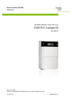
![Computador Móvel Série Mc21xx [Brazilian Portuguese] (P/N 72E](http://vs1.manualzilla.com/store/data/006087352_1-52d3c07a3e5093c41c1bf9fa502f7170-150x150.png)