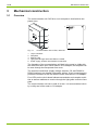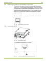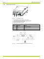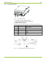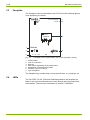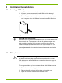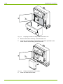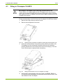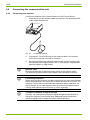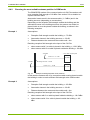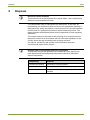
1
Communication Industrial and Commercial CU-P40, P41, P42 E65C User Manual E65C CU-P40, P41, P42 communication units provide GSM/GPRS communication between E650 or E850 meters and a central system. Date: 15.03.2012 File name: D000043188 E65C CU-P4x User Manual en.docx © Landis+Gyr D000043188 en a 2/38 Revision history Revision history Version Date Comments a 15.03.2012 First edition (derived from user manual E65C CU-P30, P31, P32 D000011691) Nothing in this document shall be construed as a representation or guarantee in respect of the performance, quality or durability of the specified product. Landis+Gyr accepts no liability whatsoever in respect of the specified product under or in relation to this document. Subject to change without notice. © Landis+Gyr D000043188 en a – E65C – CU-P40, P41, P42 – User Manual Table of contents 3/38 Table of contents Revision history...................................................................................................................................... 2 Table of contents ................................................................................................................................... 3 About this document .............................................................................................................................. 5 1 Device description........................................................................................................................ 6 1.1 Scope of application.................................................................................................................. 6 1.2 Characteristics .......................................................................................................................... 6 1.3 Type designation....................................................................................................................... 6 1.4 Functions .................................................................................................................................. 7 1.4.1 GSM/GPRS modem ............................................................................................................ 7 1.4.2 CS interface ......................................................................................................................... 7 1.4.3 RS232 interface ................................................................................................................... 7 1.4.4 RS485 interface ................................................................................................................... 7 2 Safety ............................................................................................................................................. 8 2.1 Safety information ..................................................................................................................... 8 2.2 Responsibilities ......................................................................................................................... 8 2.3 Safety regulations ..................................................................................................................... 9 3 Mechanical construction ........................................................................................................... 10 3.1 Overview ................................................................................................................................. 10 3.2 Power supply, antenna and interface connections ................................................................. 11 3.2.1 Connections CU-P40 ......................................................................................................... 11 3.2.2 Connections CU-P41 ......................................................................................................... 12 3.2.3 Connections CU-P42 ......................................................................................................... 13 3.3 Faceplate ................................................................................................................................ 14 3.4 LEDs ....................................................................................................................................... 14 4 Installation/De-installation ......................................................................................................... 15 4.1 Inserting a SIM-card ................................................................................................................ 15 4.2 Fitting in meter ........................................................................................................................ 15 4.3 Fitting in CU-adapter CU-ADP2 .............................................................................................. 17 4.4 Connecting the communication unit ........................................................................................ 18 4.4.1 Connecting the antenna .................................................................................................... 18 4.4.2 Choosing the most suitable antenna position in GSM mode ............................................. 19 4.4.3 Choosing the most suitable antenna position in GPRS mode ........................................... 20 4.4.4 Connecting the CS interface ............................................................................................. 23 4.4.5 Connecting the RS485 interface........................................................................................ 24 4.4.6 Connecting the RS232 interface........................................................................................ 24 4.4.7 Connecting the external 5 V power supply for series 2 or older meters ............................ 26 4.4.8 Connecting the external 5 V power supply for series 3 meters ......................................... 27 4.4.9 Final operations ................................................................................................................. 28 4.5 Commissioning and functional check ...................................................................................... 29 4.6 Removal/Exchange of communication unit ............................................................................. 29 5 Operation..................................................................................................................................... 30 5.1 LED status description ............................................................................................................ 30 5.2 Wrong PIN code ...................................................................................................................... 31 5.3 Signal strength indication using LEDs .................................................................................... 31 6 Service ......................................................................................................................................... 32 6.1 Troubleshooting ...................................................................................................................... 32 6.2 Repairing the communication unit ........................................................................................... 32 6.3 Repairing the 5 V power supply .............................................................................................. 33 D000043188 en a – E65C – CU-P40, P41, P42 – User Manual © Landis+Gyr 4/38 Table of contents 7 Maintenance ................................................................................................................................34 8 Disposal .......................................................................................................................................35 9 Index .............................................................................................................................................36 © Landis+Gyr D000043188 en a – E65C – CU-P40, P41, P42 – User Manual About this document 5/38 About this document Range of validity The present user manual applies to communication units E65C CU-P40, CU-P41 and CU-P42 – designated CU-P4x below. Purpose This user manual supplements the operating instructions of the meter and of the CU-adapter E65C CU-ADP2 and is incomplete without the data contained therein. Together with these operating instructions, the user manual contains all the information necessary for the operation of the CU-P4x communication unit for the intended purpose. This includes: Provision of knowledge concerning characteristics, construction and function of the communication unit CU-P4x Information about possible dangers, their consequences and measures to prevent any danger Details concerning the performance of all work throughout the service life of the communication unit CU-P4x (installation, commissioning, operation, maintenance, shutting down and disposal) Target group The contents of this user manual are intended for technically qualified personnel of energy supply companies responsible for the system planning, installation and commissioning, operation, maintenance, decommissioning and disposal of the meters. Reference documents The technical data and the functional description of the communication unit CU-P4x can be found in the following documents: D000043185 "Technical Data E65C CU-P40, P41, P42" D000011460 "Functional Description E65C CU A, B, M, G, D, P, E, Q" D000039353 "User Manual E65C CU-ADP2" D000043188 en a – E65C – CU-P40, P41, P42 – User Manual © Landis+Gyr 6/38 Device description 1 Device description 1.1 Scope of application The communication unit CU-P4x can be fitted in and removed from the following Landis+Gyr meters without opening the calibration seal: Landis+Gyr E650 ZxD300/400xT industrial and commercial meters Landis+Gyr E850 ZxQ high-precision meters Inserted in a CU-adapter CU-ADP2, the communication unit CU-P41 or CU-P42 can also be used with other meters (e.g. Landis+Gyr E650 ZxD300/400xR, ZMD100AR, ZxB or meters from other manufacturers). Connection to the meter is made in this case via an interface in the communication unit (CS, RS232 or RS485). 1.2 Characteristics The communication unit CU-P4x contains a built-in GSM/GPRS modem (mobile telephone modem with GPRS service for data transmission in packet form in GSM networks) and, depending on the version, an RS232and a CS interface (CU-P41) or an RS485- and a CS interface (CU-P42). It is used to supplement the meters listed above. The GSM/GPRS modem serves to read out or re-parameterise the meters from a central station via the mobile telephone network with GPRS via the Internet. It can also be used as a normal GSM modem. The RS485 and CS interfaces can be used for connecting meter points over a relatively long distance compared to RS232. The CS interface can be parameterised as an active or passive interface and thus can be used as master or slave as required with multiple connections. If a communication unit CU-P41 or CU-P42 is used externally in a CU-adapter, one of the existing interfaces of the communication unit is required for connection to the meter. 1.3 Type designation The type designation of the communication unit CU-P4x is added to that of the meter (see meter user manual), but is not shown on the main faceplate of the meter. It is specified directly on the case of the communication unit and can be seen through the front door of the meter through an opening on the tariff faceplate. The communication unit CU-P4x is available in the following versions: Type © Landis+Gyr GSM/GPRS modem CU-P40 CU-P41 CU-P42 RS232 RS485 CS+ D000043188 en a – E65C – CU-P40, P41, P42 – User Manual Device description 1.4 7/38 Functions A functional description of the communication unit CU-P4x is provided separately. The following main functions are briefly summarised below. 1.4.1 GSM/GPRS modem The mode of operation can either be parameterised as GSM modem or as GPRS modem. The GSM modem (GSM = Global System for Mobile Communication) is approved according to various standards such as ETS 300 607-1, EN 301 419-1 etc. It is a wireless modem (Modulator-Demodulator) for the modulated remote transmission of data via the mobile telephone network. The GSM modem uses the 850 MHz, 900 MHz, 1800 MHz and 1900 MHz GSM frequency bands. The GPRS modem (GPRS = General Packet Radio Service) uses the GSM network for data transmission, but sends and receives the data in packets. The packet-oriented data transmission permits network usage billing based on data volumes transmitted instead of connection time. GPRS permits a wireless connection to the Internet by means of transmission protocol TCP/IP (Transmission Control Protocol/Internet Protocol). 1.4.2 CS interface The serial bi-directional CS interface is standardised to IEC 62056-21 or DIN 66258. It supports both the communication protocol to IEC 62056-21 as well as communication according to dlms and can be operated both actively and passively. 1.4.3 RS232 interface The RS232 interface is an asymmetrical, serial, asynchronous, bi-directional interface to DIN 66259. This interface can be used for the (temporary) connection of a PC or laptop, in order to communicate with the meter independent of normal data acquisition. The RS232 interface of the communication unit CU-P41 has no control lines (3-wire version). 1.4.4 RS485 interface The serial bi-directional RS485 interface is standardised to ISO-8482. It is basically intended for the connection of several meters (up to 31) using the CU-P42 as the master. D000043188 en a – E65C – CU-P40, P41, P42 – User Manual © Landis+Gyr 8/38 Safety 2 Safety 2.1 Safety information The following symbols are used to draw your attention to the relevant danger level, i.e. the severity and probability of any danger, in the individual sections of this document. Danger Identifies an extraordinarily great and immediate danger that could lead to serious physical injury or death. Warning Indicates a potentially hazardous situation that may result in minor physical injury or material damage. Note Indicates general details and other useful information to help you with your work. In addition to the danger level, safety information also describes the type and source of the danger, its possible consequences and measures for avoiding the danger. 2.2 Responsibilities The owner of the communication units – usually the utility company – is responsible for assuring that all persons engaged in working with meters: Have read and understood the relevant sections of the user manual. Are appropriately qualified for the work to be performed in accordance with national regulations (see ISSA "Guideline for Assessing the Competence of Electrically Skilled Persons"). Strictly observe the safety regulations (laid down in section 2.3) and the operating instructions as specified in the individual sections. In particular, the owner of the communication units bears responsibility for the protection of persons, prevention of material damage and the training of personnel. For this purpose, Landis+Gyr provides training on a variety of products and solutions. Please contact your local Landis+Gyr representative if interested. © Landis+Gyr D000043188 en a – E65C – CU-P40, P41, P42 – User Manual Safety 2.3 9/38 Safety regulations The following safety regulations must be observed at all times: Changing of the communication unit or the 5 V supply in the terminal cover used under special conditions or the GSM antenna must only be made on meters not under voltage. Only appropriate tools shall be used for the job. This means, e.g. that the screwdriver must be of the correct size for the screws, and the handle of the screwdriver must be insulated. Devices which have fallen down should not be installed, even if no damage is apparent, and should be returned for testing to an authorised service centre (internal damage possible). Communication units must not be cleaned under running water or with compressed air. Water ingress can cause short-circuits or damage components. In addition, the safety instructions given in the user manuals for the meter and the CU-adapter CU-ADP2 are also applicable. D000043188 en a – E65C – CU-P40, P41, P42 – User Manual © Landis+Gyr 10/38 Mechanical construction 3 Mechanical construction 3.1 Overview The communication unit CU-P4x is a unit complete in itself with its own plastic case. 1 9 1 9 C G S U- P4 M /G 2 RP S 23 UP TX 5 V 42 RX CO 47 9 2 -2 01 2 2 - RS4 85 C 24 5 CS + 71 N G S M 3 4 5 Fig. 3.1 1 2 3 4 5 Communication unit CU-P4x, removed 10-pin connector Faceplate SIM-card slot Light guide through which the LEDs are visible Power supply, antenna and interface connections The faceplate of the communication unit fitted in the meter is visible with the meter front door open. When fitted in a CU-adapter, the faceplate can be seen through the transparent front cover. The external connections (supply voltage, antenna, CS- and RS485 or RS232 interface) are situated underneath, while a 10-pin connecting plug provides connection at the rear with the meter electronics or CU-adapter. Four LEDs on the circuit board indicate transmission and reception activities as well as readiness to receive through the light guide under the faceplate. The communication unit has no seal of its own. It is secured when built-in by a utility seal of the meter or CU-adapter. © Landis+Gyr D000043188 en a – E65C – CU-P40, P41, P42 – User Manual Mechanical construction 3.2 11/38 Power supply, antenna and interface connections The socket for the external 5 V supply is provided on all communication units CU-P4x. To ensure reliable modem operation, the use of an external 5 V power supply is recommended for E650 meters in some cases. Please refer to section 4.4.7 and 4.4.8 for addition information. With the screwless spring-loaded terminals of the CS interface (only present on CU-P41 and CU-P42) the polarities are determined as follows: + left terminal (23) – right terminal (24) The pins of the RJ12 socket (only present on CU-P41 and CU-P42) are numbered as follows: 6 1 Fig. 3.2 3.2.1 Pin numbering of RJ12 socket Connections CU-P40 1 Fig. 3.3 1 2 2 Connections CU-P40 Input external 5 V power supply (2-pin socket) Antenna connection (MCX socket) Fig. 3.4 Connection diagram communication unit CU-P40 D000043188 en a – E65C – CU-P40, P41, P42 – User Manual © Landis+Gyr 12/38 3.2.2 Mechanical construction Connections CU-P41 1 Fig. 3.5 1 2 3 4 2 3 4 Connections CU-P41 Input external 5 V power supply (2-pin socket) CS interface (screwless spring-type terminals WAGO) Antenna connection (MCX socket) RS232 interface (RJ12 socket) The RJ12 socket of the RS232 interface has the following pin assignment: Pin No. Terminal Signal 2 TxD Transmitted Data 3 GND Signal Ground 5 RxD Received Data Fig. 3.6 © Landis+Gyr Connection diagram communication unit CU-P41 D000043188 en a – E65C – CU-P40, P41, P42 – User Manual Mechanical construction 3.2.3 13/38 Connections CU-P42 1 Fig. 3.7 1 2 3 4 2 3 4 Connections CU-P42 Input external 5 V power supply (2-pin socket) CS interface (screwless spring-type terminals WAGO) Antenna connection (MCX socket) RS485 interface (RJ12 socket) The RJ12 socket of the RS485 interface has the following pin assignment: Pin No. Terminal Signal 1 c Signal Ground 2 a Data a 3 b Data b 4 b Data b 5 a Data a 6 c Signal Ground Fig. 3.8 Connection diagram communication unit CU-P42 D000043188 en a – E65C – CU-P40, P41, P42 – User Manual © Landis+Gyr 14/38 3.3 Mechanical construction Faceplate The faceplate of the communication unit CU-P4x has the following appearance depending on version: 99 715 479-2 2012 CU-P42 GSM/GPRS 1 2 3 23 24 7 RS485 5V CS + - C U -P42 6 4 5 TX Fig. 3.9 1 2 3 4 5 6 7 RX C ON G SM Faceplate of the communication unit CU-P4x (example CU-P42) Serial number Year of construction Diagram dlms symbol depending on parameterisation Designation of transmit/receive LEDs Insulation class and CE sign Type designation The faceplate may contain other country-specific data, e.g. warnings, etc. 3.4 LEDs The four LEDs TX, RX, CON and GSM designated on the faceplate are fitted on the circuit boards and can be seen through the light guide below the faceplate. Their function is described in section 5 "Operation". © Landis+Gyr D000043188 en a – E65C – CU-P40, P41, P42 – User Manual Installation/De-installation 15/38 4 Installation/De-installation 4.1 Inserting a SIM-card Insert a SIM-card in the communication unit as follows: 1. If present, remove a previously installed SIM-card by releasing it (pushing it in) and withdrawing it. 2. Insert the SIM-card into the slot as shown below and gently push it in until it engages. Once the SIM-card is properly inserted, it should not extend beyond the side of the device. Fig. 4.1 4.2 Correct insertion of the SIM-card Keep SIM-card contacts clean SIM-cards have electrical contacts that may come into contact with the user during normal use. The presence of oils and dirt on these contacts may cause corrosion on these contacts that are not apparent during the installation or shortly thereafter. Such corrosion may cause the contacts to become unreliable and affect the option of the communication unit. It is recommended that the user clean the contacts with a suitable solution or perform the installation in a controlled clean environment to maximize the operating life of the modem. Fitting in meter No voltage to meter when fitting In order to avoid hazardous electric shocks, ensure there is no voltage applied to the meter when fitting the communication unit. Contact with live parts is dangerous to life. Disconnect the meter from the power supply as described in the meter user manual. Fit the communication unit in the meter as follows (with SIM-card inserted according to section 4.1): 1. Ensure that no voltage is applied to the meter. 2. Remove the utility seals on the front door and terminal cover. 3. Open the front door and remove the terminal cover. D000043188 en a – E65C – CU-P40, P41, P42 – User Manual © Landis+Gyr 16/38 Installation/De-installation Fig. 4.2 4. Remove the built-in "dummy" communication unit. 5. Insert the communication unit carefully at the place provided in the meter. Ensure correct fitting of the connector. Fig. 4.3 6. © Landis+Gyr Preparing the meter for fitting the communication unit Fitting communication unit in meter Close and seal the front door. D000043188 en a – E65C – CU-P40, P41, P42 – User Manual Installation/De-installation 4.3 17/38 Fitting in CU-adapter CU-ADP2 No voltage to CU-adapter when inserting communication unit There must be no voltage applied to the CU-adapter when the communication unit is inserted. Contact with live parts is dangerous to life. If necessary, disconnect the CU-adapter from the power supply as described in the CU-ADP user manual. Fit the communication unit CU-P42 in the CU-adapter CU-ADP2 as follows: 1. Remove the utility seals on the front cover. 2. Remove the transparent front cover. Fig. 4.4 3. Insert the communication unit carefully at the position provided in the CU-adapter by first moving this forwards under the cam and then pressing down at the rear. Ensure the correct fit of the plug. The front cover should only be replaced after connecting. Fig. 4.5 4. Preparing the CU-adapter CU-ADP2 for fitting the communication unit Fitting communication unit in CU-adapter CU-ADP2 Connect the communication unit to the meter (via RS485, RS232 or CS interface) and the adapter to mains and mount the front cover, see User Manual of the CU-adapter. D000043188 en a – E65C – CU-P40, P41, P42 – User Manual © Landis+Gyr 18/38 Installation/De-installation 4.4 Connecting the communication unit 4.4.1 Connecting the antenna Connect the antenna of the communication unit CU-P4x as follows: 1. Insert the plug of the antenna cable from above in the antenna socket of the communication unit. Fig. 4.6 © Landis+Gyr Connecting antenna 2. If necessary: File a small hole for the antenna cable in the terminal cover at the required point with a round file. 3. Set up the antenna with magnetic base so that a good reception may be expected (see following section 4.4.2 "Choosing the most suitable antenna position in GSM mode"). Antenna cable Ensure that there are no physical forces acting on the antenna cable. The antenna plug fitted on the circuit board could otherwise be torn off. Positioning of antenna When setting up the antenna, movable objects such as doors and windows should be positioned in the same way as when the meter is to be read. For example, if doors will be closed after the installation during operation, the signal strength is only valid when the door is closed. Avoid places where moving metal objects can be found (e.g. cars in a garage). The effect of weather on signal strength Humidity, rain and lightning can affect signal strength measurements as well as the frequency band being used. Additional margin beyond the minimum signal level is needed to ensure reliable operation. D000043188 en a – E65C – CU-P40, P41, P42 – User Manual Installation/De-installation 4.4.2 19/38 Choosing the most suitable antenna position in GSM mode The GSM/GPRS modem of the communication unit CU-P4x needs a minimum reception field strength of -99 dBm. See section 5 for a detailed reception field level table. Attenuation losses result in the antenna cable (–1.5 dB/m) and in the building structure (depending on construction). Depending on the reception field strength outside the building and the attenuation losses in the building structure, the antenna can either be placed inside or must be placed outside the building, as shown in the following examples. Example 1 Assumptions: Reception field strength outside the building = –75 dBm Attenuation losses in the building structure = –30 dB Distance between the meter and the outside wall = 8 m Resulting reception field strength at the input of the CU-P4x: when antenna with 3 m cable is placed in the building = –109.5 dBm when antenna with 10 m cable is placed outside the building = –90 dBm -105 dBm -109.5 dBm (inadequate Cable 3 m: -4.5 dB -75 dBm CU-P4x Building structure: -30 dB Cable 10 m: -15 dB CU-P4x -90 dBm (sufficient) Fig. 4.7 Example outside placement of the antenna In this case the antenna with 10 m connection cable must be placed outside the building in order to reach sufficient field strength at the GSM modem. Example 2 Assumptions: Reception field strength outside the building = –65 dBm Attenuation losses in the building structure = –20 dB Distance between the meter and the outside wall = 8 m Resulting reception field strength at the input of the CU-P4x: when antenna with 3 m cable is placed inside the building = –89.5 dBm when antenna with 10 m cable is placed outside the building = –80 dBm D000043188 en a – E65C – CU-P40, P41, P42 – User Manual © Landis+Gyr 20/38 Installation/De-installation -85 dBm -89.5 dBm (sufficient) Cable 3 m: -4.5 dB -65 dBm CU-P4x Building structure: -20 dB Cable 10 m: -15 dB CU-P4x -80 dBm (good) Fig. 4.8 Example inside placement of the antenna In this case a sufficient reception field strength results for the antenna with 3 m cable placed inside the building as well as for the antenna with 10 m cable placed outside the building. It is therefore advisable to use the cheaper inside placement of the antenna under these circumstances. The reception field strength effectively present at the communication unit CU-P4x can be verified with the LEDs (see section 4.4.3) or more precisely with the MAP Service Tool. 4.4.3 Choosing the most suitable antenna position in GPRS mode In contrast to previous GPRS-CUs, the CU-P4x offers the possibility to measure the field strength also in case the unit is installed at a time when the GPRS window is active. You can either use .MAP110 or MAP120 for this. Both methods are described in this section. Field strength indication with .MAP110 © Landis+Gyr 1. In the command tree select the dlms Execute Command "Enable Field Strength Indication". The LED CON is switched off, the LED GSM flashes every 3 seconds. 2. Now, the LEDs TX and RX display the field strength according to the following table. Reception level Field strength level RX TX Level 1 (inadequate) <–99 dBm off off Level 2 (sufficient) –99 dBm ... –90 dBm off on Level 3 (good) –89 dBm ... –80 dBm on off Level 4 (very good) >–80 dBm on on D000043188 en a – E65C – CU-P40, P41, P42 – User Manual Installation/De-installation 21/38 3. In the command tree select the Diagnostic Command "CU GSM Installation Support" to display the current field strength at the antenna. 4. Move the antenna to find the best position. Communication via optical head for continuous display It is recommended to use the optical head for the communication between MAP and the CU because it provides a continuous display of the field strength, i.e. the display is updated if the antenna is moved. The use of a modem connection is not recommended because the display is not automatically updated while the modem connection is active. 5. In the command tree select the dlms Execute Command "Disable Field Strength Indication" to return to GPRS mode. The LED CON is now lit and the LED GSM flashes twice regularly to indicate that the GPRS mode is active. D000043188 en a – E65C – CU-P40, P41, P42 – User Manual © Landis+Gyr 22/38 Installation/De-installation Installation support in GPRS mode The reception field strength of a CU-P4x can be checked during the installlation if the GPRS window is deactivated during the start-up. The reception field strength is displayed with LEDs. It can also be read out with .MAP110 and displayed graphically. The function is deactivated with a GSM call. Once the call has been ended, the CU reactivates the GPRS window. The function can also be deactivated with the .MAP110 command "Disable field strength indication". 1. In the MAP120, select tree element "Start up State of Calling Window" and choose the option "GPRS Window disabled" to disable the GPRS mode at startup. 2. Right click on the tree element "Start up State of Calling Window" and click on "Send to Device" in the popup menu appearing. After the setting has been transferred to the CU, the CU is automatically reset and starts up in GSM mode. 3. Check the LEDs TX and RX and adjust the antenna accordingly: 4. © Landis+Gyr Reception level Field strength level RX TX Level 1 (inadequate) <–99 dBm off off Level 2 (sufficient) –99 dBm ... –90 dBm off on Level 3 (good) –89 dBm ... –80 dBm on off Level 4 (very good) >–80 dBm on on Call the CU via GSM (you can then e.g. change the parameterisation or display the field strength via .MAP110). When the call is ended, the CU activates the GPRS mode. D000043188 en a – E65C – CU-P40, P41, P42 – User Manual Installation/De-installation 4.4.4 23/38 Connecting the CS interface Connect the CS interface of communication unit CU-P41 or CU-P42 according to the connection diagram as follows: 1. Shorten the connecting wires to the required length and strip them for approx. 4 mm (wires and strands up to 2.5 mm2 can be connected). 2. If stranded wire is used as phase connection line, it has to be provided with ferrules for connection. 3. Connect the connecting wires to the screwless spring-loaded terminals (the terminals are numbered as shown on the connection diagram): – Insert a size 1 screwdriver in the upper opening and insert it turning slightly upwards (Fig. 4.9 A). – Now place the stripped connecting wire in the lower opening and hold it there securely (Fig. 4.9 B). – Withdraw the screwdriver. The connecting wire is then firmly fixed (Fig. 4.9 C). . ca A B Fig. 4.9 4m m C Connection in screwless spring-loaded terminals Bare end of connecting wire must not be too long The insulation of the connecting wire must extend as far as the terminal indentation, i.e. there must be no further bare part of the connecting wire visible above the terminal edge (as shown in Fig. 4.9 C). Touching live parts is dangerous to life. The stripped part of the connecting wire should be shortened if necessary. Only one wire or ferrule per terminal Only one wire or ferrule with strand(s) may be connected in screwless spring-loaded terminals. The terminal could be damaged or the contact could not be properly made. If a connecting wire must be disconnected again for any reason, this is performed in the reverse sequence: A Fig. 4.10 B C Releasing connection from spring-loaded terminal D000043188 en a – E65C – CU-P40, P41, P42 – User Manual © Landis+Gyr 24/38 Installation/De-installation 4.4.5 Damage to terminals Never withdraw connecting wires with the terminal closed, since this could damage the terminal. Connecting the RS485 interface Insert the connecting cable with the RJ12 connector in the right socket labelled RS485 until the connector engages. Connect the other end of the cable to the nearest unit of the RS485 multiple connection. If its RS485 interface is provided with two internally connected RJ12 sockets (e.g. CU-B2), the other end of the RS485 bus can also be provided with an RJ12 plug. If, however, only one RJ12 socket is present (e.g. CU-P42) the extension for the RS485 bus must be formed with an external splitter. External wiring of RS485 In order to function correctly, all 3 wires (data a, data b and Common GND) must be connected. RS485 operation with only 2 wires (without Common GND) is forbidden as the RS485 interface may not function correctly or be damaged. 4.4.6 Connecting the RS232 interface Insert the connecting cable with the RJ12 connector in the right socket labelled RS232 until the connector engages. Connect the other end of the cable to the desired external unit via an RS232 converter. RS232 converters RS232 converters are required for connecting external units such as modems, PCs and laptops to the RS232 interface of the communication units. These convert the RJ12 plug-in system of the communication units to the normally used D-connector system of external units. The following types of RS232 converters have been specified by Landis+Gyr: D-connector system RJ-connector system Converter type Connection for D-type Connection for RJ-type C Computer (DTE) DB9 socket Communication unit (CU) RJ12 socket F Modem (DCE) DB9 plug Communication unit (CU) RJ12 socket Key to table: © Landis+Gyr DTE DCE Data Communication Equipment (PSTN modem, GSM modem) CU Data Terminal Equipment (Computer: PC, Terminal, Laptop) Communication unit with RS232 interface D000043188 en a – E65C – CU-P40, P41, P42 – User Manual Installation/De-installation 25/38 Control lines These RS232 converters are suitable for communication units with or without control lines. For communication units without control lines (e.g. CU-P41) there is no RTS and DTR signal and the DSR signal is not connected. Significance of signals in the following converter specifications: RS232 converter type C CTS Clear To Send RTS Request To Send TxD Transmitted Data RxD Received Data DTR Data Terminal Ready DSR Data Set Ready DCD Data Carrier Detect GND Signal Ground The RS232 converter type C consists of a 9-pin DB9 socket and a 6-pin RJ12 socket, which must be wired as follows: DB9 socket Pin RJ12 socket Signal Direction 7 Signal 1 2 RxD 5 GND 6 3 Pin 2 TxD 3 GND 4 TxD 4 5 RxD 6 This RS232 converter is used for the connection between a DTE (PC, terminal, laptop) and a communication unit. RJ12 cable For connection via a cable with two RJ12 plugs (e.g. from a CU-adapter CU-ADP1 to the meter) the TxD connection must be transposed to RxD. D000043188 en a – E65C – CU-P40, P41, P42 – User Manual © Landis+Gyr 26/38 4.4.7 Installation/De-installation Connecting the external 5 V power supply for series 2 or older meters External 5 V supply is not normally required To ensure reliable modem operation, the use of an external 5 V power supply is recommended for E650 meters in the following cases: The meter is connected to less than three phases, The supply voltage phase – phase is < 173 V, The supply voltage phase – neutral is < 100 V, or The meter has an auxiliary power supply. Landis+Gyr supplies a special terminal cover with integrated 5 V supply and the required connecting cables. Use the following voltage output terminals for connecting the power supply (the terminals are numbered as shown on the connection diagram): Type of circuit Mains voltage Terminal 1 Terminal 2 M circuit < 110 V Phase (5) Phase (8) M circuit > 110 V Phase (8) Neutral (11) F circuit > 110 V Phase (5) Phase (8) Connect the external 5 V power supply of the CU-P4x as follows: 1. Insert the two pins of the 230 V input cable as follows into the screwless spring-loaded terminals according to the table above. Connection to screwless spring-loaded terminals is described in section 4.4.4. Fig. 4.11 © Landis+Gyr Connecting the 5 V power supply in the terminal cover 2. Insert the plug of the 230 V input cable in the corresponding socket of the 5 V supply in the terminal cover (the 230 V input socket is slightly wider than the 5 V output socket) 3. Insert the plug of the 5 V output cable in the corresponding socket of the 5 V supply in the terminal cover (the 5 V output socket is slightly narrower than the 230 V input socket). 4. Insert the second plug of the 5 V output cable in the CU-P4x socket. D000043188 en a – E65C – CU-P40, P41, P42 – User Manual Installation/De-installation 4.4.8 27/38 Connecting the external 5 V power supply for series 3 meters The external power supply is required for reliable communications particularly when the signal strength is weak. The CU will draw more current under such condition and sporadic network access may result when the device is not properly supplied. External 5 V supply is not normally required To ensure reliable modem operation, the use of an external 5 V power supply is recommended for E650 Series 3 meters in some cases. Conditions when external power supply is not needed: For M circuits and the supply voltage phase – neutral is 200 V nominal (or greater) where there are one, two or three phases present independent of phase angles For M circuits and the supply voltage phase – neutral is at least 58 V nominal where there are two or three phases present Auxiliary power supply is used at greater than or equal to 100 V Conditions when external power supply is needed: For M circuits and the supply voltage phase – neutral is 58 V nominal and 64 V nominal where there is only one phase present Other conditions where Landis and Gyr should be consulted: Supply voltage between 100 V nominal and 115 V nominal where there are only one or two phases present Use the following voltage output terminals for connecting the power supply (The terminals are numbered as shown on the connection diagram): Type of circuit Mains voltage Terminal 1 Terminal 2 M circuit < 110 V Phase (5) Phase (8) M circuit > 110 V Phase (8) Neutral (11) F circuit all Phase (5) Phase (8) Connect the external 5 V power supply of the CU-P4x as explained in section 4.4.7. D000043188 en a – E65C – CU-P40, P41, P42 – User Manual © Landis+Gyr 28/38 4.4.9 Installation/De-installation Final operations When all connections have been made to a CU-P4x, commissioning and functional check can be performed according to section 4.5 and then: © Landis+Gyr If the communication unit is fitted in a meter, replace the terminal cover and seal with a utility seal or If the communication unit is fitted in a CU-adapter, replace the front cover and terminal cover and seal both with utility seals. Do not pinch cables Lead the antenna cable into the grooved passage in the terminal cover and ensure when positioning the terminal cover that the various connecting cables of the communication unit are not pinched anywhere and that no physical forces are acting on the antenna cable. D000043188 en a – E65C – CU-P40, P41, P42 – User Manual Installation/De-installation 4.5 29/38 Commissioning and functional check The communication unit CU-P4x should be put into operation as follows (see also section 5 for a detailed description of the LED states): 1. Check that the GSM LED is not blinking fast. If it is, this means that the communication unit is not operational. Please refer to section 5.1 to diagnose the exact cause. 2. In GSM standby mode (established after start-up) check whether the GSM modem has found a GSM network. The GSM LED blinks every 3 seconds if a GSM network is present. Without a GSM network the GSM LED is blinking fast. 3. 4. 4.6 – If no GSM network has been found, change the position of the antenna until reception is possible (see section 4.4.2, it may be necessary to take the antenna outside or place it in another room and connect it with an extension cable). – With GSM network, check the reception quality with the help of the two LEDs RX and TX on the faceplate. At least the RX LED should be on, preferably both. If this is not the case, a better antenna position has to be found (see section 4.4.3) until at least the RX LED lights. Make a GSM call to the CU. After termination of this call, the CU reactivates the GPRS window. In GPRS mode, depending on whether it is fixed IP mode or dynamic IP mode, the CON LED is either blinking slowly or continuously on. Reliable operation Operation without failure is only ensured when the reception level is good or very good, i.e. when on GSM standby mode (no connection made) at least the RX LED or both LEDs TX and RX are on. 5. As a functional check of the modem connection perform a remote readout of the meter data via the mobile telephone network. 6. If multiple connections to additional devices are needed, check that they can also be read. Removal/Exchange of communication unit The communication unit is exchanged or removed from the meter in reverse order of the installation (see sections 4.2 and 4.3). D000043188 en a – E65C – CU-P40, P41, P42 – User Manual © Landis+Gyr 30/38 5 Operation Operation The communication unit CU-P4x features four LEDs to display status information on the operation state. These LEDs are visible through below the faceplate. 5.1 LED status description LED RX (orange) TX (orange) CON (green) GSM (yellow)1 Fast blinking Status SIM-card missing or defective Blinking intermittently for modem initialisation (repeated every 14 s) off Wrong PIN code2 Fast blinking Fast blinking Fast blinking Fast blinking (0.5 s on/0.5 s off) (0.5 s on/0.5 s off) (0.5 s on/0.5 s off) (0.5 s on/0.5 s off) CSD call setup in progress either in GSM mode or GPRS mode Flickering when data received3 Flickering when data sent3 Fast blinking on GSM standby mode Field strength indication, see table in section 5.3 Field strength indication, see table in section 5.3 Blinks every 3 s, if ≥ 3 stations received, off if < 3 stations Slow blinking GSM data transfer mode Flickering when either in GSM mode or data received3 GPRS mode Flickering when data sent3 on on IP address is being fetched4 Flickering when data received3 Flickering when data sent3 Slow blinking Slow blinking (1 s on/1 s off) (0.3 s on/2.7 s off) Offline mode (fetching IP address failed, connection lost, etc.)4 Flickering when data received3 Flickering when data sent3 off Fast blinking GPRS fixed IP standby mode Flickering when data received3 Flickering when data received3 Slow blinking Slow blinking (2 s on /1 s off) (0.3 s on/2.7 s off) GPRS fixed IP or dynamic IP data transfer mode with data transfer Flickering when data received3 Flickering when data sent3 on Slow blinking CU has connected with dynamic IP server but no data transfer Flickering when data received3 Flickering when data received3 on © Landis+Gyr (0.5 s on/0.5 s off) (0.5 s on/0.5 s off) (0.3 s on/2.7 s off) (0.5 s on/0.5 s off) (0.3 s on/2.7 s off) Slow blinking (0.3 s on/2.7 s off) 1 GSM LED: Fast blinking means there is a condition that prevents communications to be established. Slow blinking or on indicates normal operation. 2 Check PIN code or deactivate it via mobile phone on the SIM-card, see instructions in section 5.2 "Wrong PIN code" 3 Via GSM/GPRS modem or RS232 interface or RS485 interface or wireless modem activity 4 Check the TCP/IP settings of the CU D000043188 en a – E65C – CU-P40, P41, P42 – User Manual Operation 5.2 31/38 Wrong PIN code If all LEDs are fast blinking (0.5 s on/0.5 s off), an incorrect PIN code has been parameterised for the SIM-card used. In this case, the user must set the correct PIN code before restarting the module by power cycling the CU. Please note that after three attempts with the wrong PIN code (which can be triggered by 3 power cycles of the CU) it will require the use of the PUK code to enable further PIN code attempts. The user can deactivate the PIN code of the SIM-card with a mobile telephone. 5.3 Signal strength indication using LEDs In certain states, the LEDs RX and TX indicate the signal strength as follows: Reception level Field strength level RX TX Level 1 (inadequate) <–99 dBm off off Level 2 (sufficient) –99 dBm ... –90 dBm off on Level 3 (good) –89 dBm ... –80 dBm on off Level 4 (very good) >–80 dBm on on D000043188 en a – E65C – CU-P40, P41, P42 – User Manual © Landis+Gyr 32/38 Service 6 Service 6.1 Troubleshooting The following points should be checked when the system does not operate regarding the GSM/GPRS modem connection or the interfaces: 1. Is the mains voltage present (meter liquid crystal display legible, green LED on CU-adapter is on)? 2. Is the GSM signal level sufficient (at least RX LED is on)? 3. Is the maximum permissible ambient temperature not exceeded? 4. Are there any changes or damage visible in the installation? 5. Check the status of the LEDs according to section 5 "Operation". If none of the points listed leads to a resolution of the fault, the communication unit should be removed and sent to the responsible service and repair centre. 6.2 Repairing the communication unit Communication units must only be repaired by an authorised service and repair centre (or by the manufacturer). Meter operation only with communication unit or "dummy" For safety reasons the meter must not be operated without communication unit or a "dummy" communication unit. Adopt the following procedure if a repair is necessary to the communication unit: © Landis+Gyr 1. If installed, remove the communication unit and fit a replacement communication unit. If no spare communication unit is available, a "dummy" unit must be used. 2. Describe the error found as exactly as possible and state the name and telephone number of the person responsible in case of inquiries. 3. Pack the communication unit to ensure it can suffer no further damage during transport. Preferably use the original packing if available. Do not enclose any loose components. 4. Send the communication unit to the responsible service and repair centre. D000043188 en a – E65C – CU-P40, P41, P42 – User Manual Service 6.3 33/38 Repairing the 5 V power supply 5 V power supplies must only be repaired by the responsible service and repair centre (or manufacturer). Adopt the following procedure if a repair is necessary to the 5 V power supply: 1. Remove the terminal cover with built-in 5 V supply and install a replacement if necessary. Removal of the connections is made in a similar way to connection but in the reverse sequence (see section 4.4.7). 2. Describe the error found as exactly as possible and state the name and telephone number of the person responsible in case of inquiries. 3. Pack the terminal cover with built-in 5 V power supply to ensure it can suffer no further damage during transport. Preferably use the original packing if available. Do not enclose any loose components. 4. Send the terminal cover with built-in 5 V power supply to the responsible service and repair centre. D000043188 en a – E65C – CU-P40, P41, P42 – User Manual © Landis+Gyr 34/38 7 Maintenance Maintenance The communication unit CU-P4x requires no maintenance. Never use running water for cleaning Communication units must not be cleaned under running water or with compressed air. Water ingress can cause short-circuits or damage components. © Landis+Gyr D000043188 en a – E65C – CU-P40, P41, P42 – User Manual Disposal 8 35/38 Disposal Electronic waste treatment This product must not be disposed of in regular waste. Use a professional electronic waste treatment process. The components used to manufacture the device can, in the main, be broken down into constituent parts and sent to an appropriate recycling or disposal facility. When the product is removed from use, the whole product must be sent to a professional electronic waste treatment process. The waste treatment and disposal plants must be approved by local regulatory authorities. The end processing of the product and recycling of its components must always be carried out in accordance with the rules and regulations of the country where the end processing and recycling are done. On request, Landis+Gyr will provide more information about the environmental impact of the product. Disposal and environmental protection regulations The following are general guidelines and should NOT take priority over local disposal and environmental policies which should be adhered to without compromise. Components Disposal Printed circuit boards Delivered to recycling plants Metal components Sorted and delivered to metal recycling plants Plastic components Sorted and delivered to re-granulation if at all possible D000043188 en a – E65C – CU-P40, P41, P42 – User Manual © Landis+Gyr 36/38 9 Index Index About this document ....................................... 5 Antenna position ........................................... 19 Characteristics ................................................ 6 Checking the network presence indication ... 29 Checking the reception quality ..................... 29 Choosing the most suitable antenna position 19 Commissioning ............................................. 29 Connecting Antenna.................................................... 18 CS interface ............................................. 23 External 5 V power supply ................. 26, 27 RS232 interface ....................................... 24 RS485 interface ....................................... 24 Connection diagram CU-P40 .................................................... 11 CU-P41 .................................................... 12 CU-P42 .................................................... 13 Connections .................................................. 11 CU-P40 .................................................... 11 CU-P41 .................................................... 12 CU-P42 .................................................... 13 CS interface .................................................... 7 CU-adapter CU-ADP1 .................................. 17 De-installation ............................................... 15 Device description .......................................... 6 Disposal ........................................................ 35 Disposal regulations ..................................... 35 Electronic waste treatment ........................... 35 Environmental protection regulations ........... 35 Faceplate ...................................................... 14 Fitting in meter .................................................... 15 Fitting in CU-adapter .............................................. 17 Functional check ........................................... 29 © Landis+Gyr Functions of LEDs ........................................ 30 GSM/GPRS modem ....................................... 7 Inserting a SIM-card ..................................... 15 Installation .................................................... 15 Interface connections ................................... 11 LEDs ............................................................. 14 Maintenance ................................................. 34 Mechanical construction ............................... 10 Network presence indication......................... 29 Operation ...................................................... 30 PIN code of SIM-card .................................... 31 Power supply repair ...................................... 33 PUK of SIM-card ........................................... 31 PUK release number .................................... 31 Reception quality .......................................... 29 Releasing connection from spring-loaded terminal .................................................... 23 Removal of communication unit.................... 29 Repairing the 5 V power supply .................... 33 Repairing the communication unit ................ 32 Responsibilities ............................................... 8 RS232 converter ..................................... 24, 25 RS232 interface .............................................. 7 RS485 interface .............................................. 7 Safety Regulations ................................................ 9 Scope of application ....................................... 6 Seals ............................................................. 10 Service .......................................................... 32 SIM-card blocked .......................................... 31 SIM-card holder ............................................ 10 TCP/IP ............................................................ 7 Troubleshooting ............................................ 32 Type designation ............................................ 6 Versions .......................................................... 6 D000043188 en a – E65C – CU-P40, P41, P42 – User Manual Index D000043188 en a – E65C – CU-P40, P41, P42 – User Manual 37/38 © Landis+Gyr Contact: Landis+Gyr (Europe) AG Theilerstrasse 1 CH-6301 Zug Switzerland Phone: +41 41 935 6000 www.landisgyr.com