1
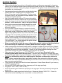
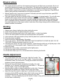
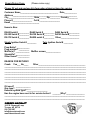
TM
DA60
Owners Manual
11/10
Safety Instructions
READ THIS!
WARNING!
This motor can cause severe harm to you, and/or others, if misused or if these safety
precautions and instructions are not observed. Desert Aircraft is not responsible for
any loss, injury or damage resulting from the miss-use of its products.
You alone are responsible for the safe operation of your motor.
This motor can stop at any time, for a variety of reasons. Do not fly your plane in such
a way that damage or harm will result if the motor stops running.
•
•
•
•
•
•
•
•
•
•
•
•
•
•
•
•
•
•
•
•
•
•
•
Do not operate this motor if you do not want to be completely responsible for any damage or injury
incurred or caused during its operation.
Read all instructions before operating your motor.
If you have any questions about any aspect of operating this motor, do not attempt to start or
operate it.
Never operate the motor, or fly, alone.
When operating the motor, never stand, or allow anyone else to stand, in front of, or to the side of
the propeller. Always stand behind the propeller.
Keep away from the prop while operating the motor. Do not wear loose clothing near the motor or
prop. Do not run the motor near loose material such as dirt, gravel, power cords, ropes, sand, etc.
Loose material can be drawn into the turning prop causing injury or damage.
Always operate the motor in an open area. Do not operate indoors.
This motor can develop tremendous thrust. Make sure the aircraft is properly secured when starting
or operating the motor.
Inspect motor mount bolts and firewall integrity before operating the motor.
Anyone in the immediate area of the motor should use eye protection during operation of the motor.
Keep spectators at least 30 feet away when operating the motor.
Turn off the motor before making any adjustments.
Always use the correct length propeller bolts. Do not use spacers behind the propeller.
Spinner cones must not touch the propeller.
Thinner props may require using shorter prop bolts, especially if not using a spinner back plate.
Make sure your prop bolts do not bottom out in the propeller hub.
Check that the propeller bolts are tight before every flight.
Always install an ignition kill switch to stop the motor.
Adjust the carburetor linkage so that the motor will stop when the carburetor is completely closed.
Gasoline is extremely flammable. Be careful of any sparks from electrical contacts such as fuel
pumps, battery chargers, etc. Do not allow smoking in the area of your fuel supply or motor. Store
fuel in approved containers and in well ventilated areas.
Allow the motor to cool before touching or fueling.
Always flip the prop a few revolutions after running the motor to discharge the ignition system.
The ignition system develops extremely high voltage. Do not touch it during operation.
Never use a damaged, modified, or repaired prop, or a prop that has struck the ground or any other
object. Damage that can be hard to see, could turn into disaster when the prop is turning at
thousands of RPM.
1
Motor Installation
•
•
•
•
•
•
•
•
•
•
•
•
•
Mount the motor using high grade 1/4" or 6mm dia. bolts with washers and locking nuts on the rear
of the firewall. Make sure your firewall is structurally sound. The crankshaft centerline is in the exact
center of the rear mounting plate bolt pattern.
The preferred method to mount the DA60 is for the engine to bolt directly to the firewall, with the carb
protruding through a hole in the firewall. This may require removing the firewall and extending the
motor box and firewall to the proper dimension that lets the prop hub protrude from the cowl far
enough to ensure clearance for the spinner back plate.
Standoff mounts are not recommended and can damage the engines crankcase. Rigid, full contact
mounting can reduce vibration. If the engine needs to be spaced off the firewall, we recommend
making a full contact spacer by laminating aircraft plywood to the required thickness.
The throttle arm is pre-tapped for a 2-56 linkage. Do not use a clevis type connector. Make sure the
carburetor's idle set screw is removed or set so that the carb can be fully closed by the servo at low
trim. Use a high quality servo for the throttle. A poor quality servo or linkage will not provide
accurate and repeatable throttle settings. Don't use metal to metal linkages.
You can un-hook, but don't remove, the throttle return spring if the motor is not going to be bench
run.
Do not remove the carb's choke or throttle butterfly shaft assemblies.
The carburetor should have at least 1/2" (13mm) of clearance between the intake and the fire wall or
any other object that can restrict airflow into the carb. If necessary, make an opening in the firewall to
clear the carb.
Since the cowl effects air flow and pressures, we recommend that the carburetor needles can be
adjusted with the cowl on. To do this, small access holes can be made in the cowl for using a long
narrow screw driver to adjust the needle valves. Short guide tubes can often be glued into the
firewall or spacer mount to help guide the screw driver to the needles.
A 24 oz. (or larger) fuel tank is recommended. The tank must be vented. The carb has a strong
pump, so the tank can be mounted almost anywhere in the plane. Keep the fuel line away from any
hot engine or exhaust components. The fuel line and tank stopper must be gas compatible. Do not
use any silicone sealers on the fuel system. Gas can break it down and carry it into the carb.
The inner diameter of the fuel tubing should be the same size or slightly larger than the carburetor's
fuel inlet fitting's inner diameter. We use 1/8" Tygon tubing. Make sure all fuel line connections are
secure. Small nylon zip ties work well to keep the fuel line on the metal fittings. Make sure the fuel
line is secure and not touching the exhaust or cylinder fins. An inline fuel filter can be used. We
highly recommend filtering the gas entering the fuel tank from your field container.
Cooling is critical to motor performance and longevity. Allow as much cooling air as possible in
through the front inlets of the cowl. Air must flow through the cylinder fins, not just inside the cowl, to
properly cool the motor. Don't let the air take the easy way out! Make it go through the fins. Round
cowls with large frontal openings need ducting to direct the air through the cylinder fins. Allow an
outlet opening approximately 2 1/2 times larger than the intake at the bottom rear of the cowl for the
hot air to escape. Without this outlet opening, air won't flow through the cowl.
Air ducts can be made from thin plywood, balsa, fiberglass, or aluminum sheet to guide and force air
from the front inlets to and through the cylinder fins.
Keep components like the ignition system, fuel tank, fuel lines, receivers, etc, shielded from heat
generated by canister and tuned pipe exhaust systems. Hot fuel tanks and fuel lines can cause
frustrating tuning issues, and over heated electronic components can have intermittent problems or
total failures.
2
Ignition System
•
When making electrical connections to the ignition system, use the same gauge wire (or larger) as
used on the red and black power leads on the ignition module, all the way to the battery pack. Keep
wire length to a minimum. Heavy-duty plugs, as supplied on the ignition, or as used on electric cars
and planes, are recommended.
• We recommend mounting the ignition on high density foam
padding with Velcro strapping. Do not use sticky back
Velcro or foam tape to mount the module. This can cause
the case to crack in the area where the tape adheres to the
module and void the warranty.
• Use a high quality switch such as JR’s heavy-duty switch.
Standard size R/C receiver switches are not recommended.
• Isolate the charge circuit from the ignition while charging the
batteries. In other words don’t “charge” the ignition module.
• Keep ignition components and wiring separated, as much
as possible, from your receiver, receiver battery, servos,
wiring and switches.
• Don’t use metal-to-metal linkages to operate the throttle.
• Use a 4.8 or 6 volt battery pack. The ignition can handle the
higher peak voltage of these packs when fully charged.
Higher voltage packs (Lithium, etc) can be used, but require
a regulator. We recommend a regulator with a 5.5 or 6 volt
output. Excessive voltage will damage the ignition system
and will void the warranty. We recommend an1800 mAh or
larger capacity pack. This size pack should be sufficient for
5 or more flights. If the voltage entering the ignition shows
5.0 volts or less, don’t fly, re-charge.
• When connecting the red pick-up sensor to the ignition module, make sure that the polarity of
the wires entering the connectors is correct (Brown to brown, orange to orange)
• Unlike some ignitions, the Desert Aircraft ignition is designed to spark only when the prop is flipped
at a high speed. If the prop is not turned over at "starting" speed, the ignition will not fire. This helps
to prevent the motor from firing accidentally. Unless you are having problems starting the motor,
don’t bother “testing” the ignition with the plug removed from the cylinder.
• When removing the spark plug caps, PULL STRAIGHT out on the caps. Do not pull on the
shielded ignition wires and do not use pliers! To prevent radio interference, the spark plug caps
must have the split retainer ring around the base to insure a tight fit. – DON’T FLY WITHOUT THEM!
• Protect the shielded plug wires from rubbing against fiberglass or sharp edges of wood or
metal. Rubber grommets and plastic “spiral wrap” insulation from automotive or electronic supply
stores work well. Holes in the braided shielding can emit R/F noise or loose connections (spark plug
caps, connectors and switches).
• Timing is set at the factory and should not need adjustment. Contact Desert Aircraft if you have any
questions regarding timing.
• Only use NGK CM-6 spark plugs. Other plugs may not fit the plug caps firmly.
• Plug gap is .018” to .020" (.38 to .50 mm)
• Never operate the ignition without a spark plug in the plug caps! This can permanently damage the
ignition coil.
• Always perform a radio range check before flying. If there are “glitches”, DON’T FLY! Check for
holes in the braided shielding, loose connections, or other radio issues .
3
Recommended Props
•
•
•
•
•
•
•
•
•
•
•
•
•
Always check and tighten prop bolts before each flight! Loose prop bolts allow prop movement,
which will shear the bolts.
Always use the correct length prop bolts. If a spinner back plate is not used, the prop bolts may be
too long and can bottom out in the hub before they fully tighten against the prop washer.
The DA60 has a very wide power band. The "normal" peak operating rpm is 6,300 to 7,300 rpm.
While special break-in props are not required, be careful to not overload the engine during break-in.
Some recommended props are:
Wood: 22x10, 23x8, 23x10, 24x8, 24x10
Mejzlik Carbon: 23x8, 23x10, 24x10, 24x10 TH,
Mejzlik Carbon 3 blade: 21x12, 22x10
A general rule of thumb for good flight performance is the larger and/or heavier the plane, the lighter
the prop load to allow the engine to create more horse power. On a lighter/smaller/cleaner airframe
horsepower requirements are not as critical. You may enjoy the benefits of a larger prop disc for
better down line braking, torque rolling, etc.
Smaller diameter props with more pitch, especially 3 blades, can reduce tip speed and noise.
Always use a drill guide to drill your props. We normally drill from the back side first, then again from
the front to insure the screws don’t bind in the holes.
Always check the balance of your prop
For safety, we recommend painting the tips of your props (front and back) with a bright color,
especially on black props.
Never use a damaged or repaired prop, or a prop that has struck the ground or any other object.
Damage that can be hard to see could turn into disaster when turning at thousands of RPM.
Fuel and Oil Mix
•
•
•
•
•
•
•
Use Premium pump gas, such as 91 to 93 octane.
We recommend purchasing your fuel from “name brand” gas stations. We have seen problems with
cheaper gas from some discount type outlets.
We recommend filtering your fuel between your fuel container and your plane’s fuel tank. A high
flow filter, or clunk/filter, between the tank and motor is also a good idea.
Make sure the plane’s tank is well vented and the fuel clunk moves freely.
Use of any other fuel or additives such as nitro formulas, aviation gas, white gas, etc., can
harm the motor and void the warranty.
Do not use silicone sealers on the fuel system. Gas can break it down and carry it into the carb.
We recommend a high quality synthetic oil. As for brand of oil, there are many good ones on the
market. Some oils, and their mix ratios, that Desert Aircraft recommends are: Red-line Two Stroke
Racing Oil (40 to 1), Motul 800 (50 to 1), and Stihl HP Ultra (50 to 1). These oils can be found at
most motorcycle or chainsaw shops. An option for initial break-in, is to use a petroleum-based oil
such as Lawn Boy Ashless 2 stroke oil mixed at 32 to 1. This can speed ring seating and limit the
opportunity for blow by that can cause permanent damage. 2 gallons fuel/oil mix is sufficient. (Mix 2
gallons of premium gas with 8 oz of oil.) The rings can seat in correctly without using petroleumbased oil, but it will take longer.
4
Break-in phase
•
•
•
The engine should run well from the beginning and improve as flight hours accumulate. We do not
recommend breaking the engine in on a test stand. The stationary load and lack of air ducting can
lead to engine over heating. Proceed with flying once the engine is tuned and running correctly.
Engine break-in can be a slow process, taking place over many hours of flight time. Peak RPM will
improve along with idle characteristics as run time accumulates.
Special "break in only" props are not required. Preferably start with a prop that allows peak RPM
over 6,300 during the break-in process.
The High needle can be set for optimum RPM or just slightly rich during break-in. Too rich will cause
problems with excess residue and carbon build up. Adjust the needles as needed and give the
engine a few test flights using a variety of throttle settings and engine loads. Avoid extended high
rpm or extended hovering conditions for these first few flights. After a few test flights the needles
may need adjustment as the engine settles in and when other things change such as different props,
exhaust, weather, and altitude.
Starting
1.
2.
3.
4.
5.
6.
7.
8.
Always wear a heavy leather glove when starting the motor.
Check that prop bolts are tight and spinner is secure.
Make sure the starting area is free of dirt, sand, gravel, or other loose debris
Turn on the radio system and check the throttle operation and position.
Have someone (with eye protection) firmly hold the plane from a position behind the wing.
Close the choke completely.
Open the throttle to approximately 1/4 position.
Turn on the ignition. ALWAYS BE PREPARED FOR THE MOTOR TO START ON ANY FLIP OF
THE PROP, whether the ignition switch is on or off!
9. Give the prop a quick, firm, flip counter clockwise. Follow through quickly as you flip the prop so that
your hand is out of the propeller's path. Repeat until the motor fires or “pops”.
10. Open the choke.
11. Set throttle to idle position. (carb butterfly plate slightly open)
12. Flip the prop again until the motor runs.
13. Let the motor warm up for 15 or 20 seconds before advancing the throttle.
Needle Adjustments
•
•
•
•
High
Low
The needle farthest from the motor is the “High End” needle. The
needle closest to motor is the “Low End” needle. Turning the needles
in/clockwise “leans” the fuel mixture. Turning the needles out/counterclockwise “richens” the fuel mixture.
Settings will vary with altitude, temperature, humidity, fuel, carb
variances, etc. A "general" starting point for the DA60 is: 1 1/8 open on
the Low needle, 1 open on the High needle.
Adjusting either needle can have a slight effect on the other. Example:
Leaning the low needle can "slightly" lean the high rpm range.
Adjust the High End needle to peak rpm. A tachometer can help, but
remember that the RPM normally drops a little bit after every start due
to residual heat build up. Don’t lean the mixture any more than
necessary. If the rpm steadily drops at full throttle or fades on long vertical maneuvers, the motor is
too lean and is overheating.
(Cont'd)
5
Needle Adjustments
(Cont'd)
•
Adjust the Low End needle until you achieve a smooth idle and a reliable transition to high throttle.
Generally if the motor “stutters” or “coughs” in the mid range or when the throttle is advanced, the
low end needle is too rich and possibly even the high end needle. If the motor dies quickly, the low
end is probably lean.
• Don't set the needles overly rich to protect the engine. Operating the motor overly rich not only
reduces power, it creates other problems such as poor transition, pre-mature carbon build up, fouled
plugs, excessive exhaust residue, sticking rings, airframe vibration, and overall rough running.
Trouble Shooting
Motor won't start:
•
•
•
•
•
Check battery voltage (should be 5.0+ volts) and all ignition connections, wiring and switches. Wires
can break from vibration near connectors. Check and/or swap out regulator.
Does fuel move towards the carb when the prop is flipped? If not, check tank venting, clunk position,
and fuel lines for leaks. Is the choke plate closing completely? Is the carb or carb mount loose
causing an air leak? Air leaks on the engine usually show as fuel seepage.
Is throttle set at idle or slightly higher after motor “pops” and choke is opened?
Make sure prop is flipped over with authority. The ignition won’t fire at low speed.
If a lot of fuel drips from carb, the motor might be flooded. If so, remove and dry, or replace, the
spark plug. Try starting again without using the choke. If engine doesn't fire after several flips, try
choking again.
Other issues:
•
•
•
•
•
RPM won’t go over 3,500 to 4,000: The connector between the ignition module and ignition sensor
may be plugged in backwards. Check the color of the wires leading into the connectors to make
sure that the polarity is correct.
Broken prop bolts: In order for bolts to shear, some type of side loading (shear) movement is
usually required. If the bolts are tightened correctly, nothing moves and prop bolts will rarely break.
It’s a good idea to replace prop bolts routinely. Check prop bolts before each flight!
Excessive vibration: Check that the low rpm needle setting is not too rich. Check prop and spinner
balance. Make sure ignition timing is correct. Check the firewall and motor box area of the aircraft
for movement, poor glue joints, etc. This area must be rigid! Some aircraft on the market are lacking
in this area and may require additional glue and/or structure. Poor quality or contaminated fuel can
cause rough running.
Pink or purple colored cylinders: These colors indicate engine temperature has been too high at
some point. Check that needle settings are not too lean, air flow for cooling is sufficient, and oil/gas
mixture is correct.
Engine starts backwards: 2 stroke reed valve engines can generally run in either direction. Make
sure the prop is flipped forcefully through the compression stroke. Without enough force, the prop
may "bounce" off compression and run backwards.
IF ANY PROBLEM PERSISTS, PLEASE CONTACT DESERT AIRCRAFT FIRST!
We designed and manufactured your engine and have built, serviced, and analyzed
thousands more. We cover your engine’s warranty, not someone at the field or a stranger
on the Internet. Please give us the opportunity to help first!
6
Maintenance
•
•
•
Being a high performance 2 stroke engine, certain parts can wear quickly. Under normal operation,
pistons, piston rings, needle bearings, spark plugs, etc. may need occasional non-warranty
replacement to insure peak performance. Other factors can hasten the need for replacement parts
such as ingested dirt and debris, exceedingly high temperatures due to improper lubrication, airflow,
improper needle adjustments, excessive prop loads, etc.
If the engine has been involved in a crash or severe prop strike, inspect it carefully for any signs of
damage before operating the engine. Make sure nothing was ingested into the engine. Check that
the prop hub rotates freely and without any "run out" or wobble. Look for any signs of cracks in the
case, especially near the motor mount area. If the spark plug cap shows any damage, do not
operate the ignition. If there is a short inside the cap, it can cause damage to the ignition module.
Screws can come loose! After a few flights check that all screws are secure. Periodically check that
all screws are tightened to the correct torque rating. It's recommended to replace, rather than re-use
the red aluminum screws whenever they are removed. If exhaust flange screws become loose, the
flange face and threaded holes can be damaged to the point where the header or muffler won't stay
tight and the cylinder needs to be repaired or replaced.
Torque specifications
Spark plug:
Steel prop bolts:
Aluminum crankcase bolts:
Steel cylinder base bolts:
Aluminum carb mount bolts:
Size
CM-6, 10mm
M5x 45mm
M5x16mm
M5x16mm
M5x75mm
Torque setting
90 in. lbs.
75 in. lbs. / wood props, 90 in. lbs. /carbon props.
70 in. lbs.
95 in. lbs.
50 in. lbs.*
.
*Caution: Care must be taken to not over tighten the carb mounting bolts. Over tightening can
distort and damage the injected molded reed valve parts and rubber gaskets.
•
•
•
•
•
Use a 4m hex wrench for all M5 cap screws.
For spinner mounting, the crankshaft extension is threaded for M5 screws. In this application
(steel to steel) the 10-32 SAE screws supplied with most spinners will work fine in the M5
threaded hole. Do not substitute 10-32 screws for any other screws on the engine!
Inspect the engine periodically for any signs of fuel seepage. This can indicate an air leak which
can create a lean fuel/air ratio, which in turn can cause erratic running and engine damage. If
tightening the appropriate screws does not cure the problem, contact Desert Aircraft.
After prolonged use, carbon deposits can build up on top of the piston and on the combustion
dome of the cylinder. Great care must be taken when trying to remove these carbon deposits to
avoid damaging the parts. Once an attempt to remove carbon has been made, the task must be
completed, as any remaining carbon may be loosened and can dislodge while the engine is
running. This can damage the engine and/or bridge the spark plug.
If the engine is going to be stored for a long period of time, it is recommended to run a few
minutes worth of non-ethanol fuel through the engine. This can help reduce the chance of
corrosion from water associated with ethanol in gasoline. Often larger gas stations offer "race
gas" or other high octane ethanol-free gas.
Manuals may be updated with additional tips and trouble-shooting info from time to time. Please check
our web site, www.desertaircraft.com, for current downloadable manuals and updates or contact Desert
Aircraft.
7
DA60 WARRANTY
Your DA60 motor and ignition system are covered with a 3 year warranty
by Desert Aircraft, starting from the date of purchase.
•
•
•
This warranty covers defects in workmanship and materials only.
We strongly recommend to not disassemble the motor or ignition system. Improper disassembly or
assembly of the motor or ignition system will void the warranty on that item.
Any modifications to the motor, or the ignition system, other than those authorized by Desert Aircraft,
will void this warranty.
This warranty does not cover the following:
•
•
•
•
•
Shipping expenses to and from Desert Aircraft for warranty service.
Damage caused by improper handling, operation, or maintenance.
Damage caused by a crash.
Damage caused by using improper fuel or additives.
Damage incurred during transit to Desert Aircraft. WRAP AND PACK ENGINE CAREFULLY!!
NOTE: DESERT AIRCRAFT WILL NOT SHIP ANY WARRANTY REPLACEMENT
ITEMS UNTIL THE POSSIBLY DEFECTIVE ITEMS IN QUESTION ARE
RETURNTEND TO AND RECEIVED AND DEEMED DEFECTIVE BY
DESERT AIRCRAFT.
Remember! This motor can stop at any time, for a variety of reasons. Do not fly
your plane in a way that damage or harm will result if the motor stops running.
Desert Aircraft will not be responsible for damage caused in engine–out situations.
DESERT AIRCRAFT
1815 S. Research Loop
Tucson, AZ 85710 USA
Ph 520 722 0607 Fax 520 722 5622
Email [email protected]
Web www.desertaircraft.com
8
Repair/Return Form
(Please make copy)
Please fill out and enclose this form when shipping items for service
Customer Name_________________________________ Date___________
Address________________________________________________________
City______________________ State______ Zip_________ Country________
Phone #_________________ Cell #__________________
Email _________________________
Items in Box:
DA50 Serial #__________ DA60 Serial #__________ DA85 Serial #__________
DA100 Serial #_________ DA120 Serial #_________ DA150 Serial #_________
DA170 Serial #_________ DA200 serial #_________ Other________________
Single Ignition Serial # ________
Twin Ignition Serial # ________
Prop Bolts? ___________
Prop washer? _________
Muffler(s)? ____________ Muffler screws_____________
Standoffs? ____________
Other Items? __________
REASON FOR RETURN?
Crash: Yes___ No____
Other_________________________________________
_______________________________________________________________________
_______________________________________________________________________
_______________________________________________________________________
_______________________________________________________________________
_______________________________________________________________________
_______________________________________________________________________
_______________________________________________________________________
Oil used? _____________
Gas type? _____________
Exhaust system type? __________________
Has the engine been sent in for service before? _______Why?________________
______________________________________________________________________
______________________________________________________________________
DESERT AIRCRAFT
1815 S. Research Loop
Tucson, AZ 85710
520 722 0607
[email protected]
www.desertaircraft.com