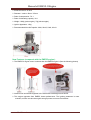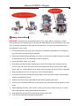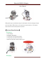
1
Manual of EME55-II Engine
User Manual
EME gasoline engine is professional design for model airplane. With the advantages of weight,
power and stability, EME provides you the opportunity on power selection on TOC airplane.
Please read the manual carefully before the operation.
【Technical Specifications】
】
Performance:
5.5HP/7500rpm
Idle Speed: 1350 rpm/min.
14.2kg Pulling Force/100 meters Altitude.
12.5kg Pulling Force/1800 meters Altitude.
Spark Plug: NGK CM6, operating voltage: 4.8-6V
Parameters:
www.sdshobby.net
1
Manual of EME55-II Engine
Exhaust Amount: 55.6CC
Diameter * stroke: 45mm * 35mm
Ratio of compression: 7.6:1
Ratio of lubricating capacity: 30:1
Weight: 1380g (main engine), 75g (exhaust pipe)
Ignition Apparatus: 120g
Recommended Aircraft Propeller: 22x8; 22x10; 23x8; 23x10
New Features (compared with the EME55 engine):
The EME55-II engine mount is shorter than the EME55 engine’s.(See the following photos)
Install mount and throttle regulator is the same with DA-60engine and DLE55.
This engine upgrades from EME55, better performance. The ignition parameter is more
scientific, ensure to make the engine stronger power and more fuel-efficient.
www.sdshobby.net
2
Manual of EME55-II Engine
【Safety Instructions】
】
WARNING! This motor can cause severe harm to you, and/or others, if misused or if these
safety precautions and instructions are not observed. EME Engines is not responsible for any loss,
injury or damage resulting from the miss-use of its products. You alone are responsible for the
safe operation of your motor.
Do not operate the motor if you do not want to be completely responsible for any damage or
injury incurred or caused during its operation.
Read all instructions before operating your motor. If you have any questions about any aspect
of operating this motor, do not attempt to start or operate it.
Never operate the motor, or fly, alone.
Keep away from the prop while operating the motor. Do not wear loose clothing near the
motor or prop. Do not run the motor near loose material such as dirt, gravel, power cords,
ropes, sand, etc. Loose material can be drawn into the turning prop causing injury or damage.
Always operate the motor in an open area. Do not operate indoors.
This motor can develop tremendous thrust. Make sure the aircraft is properly secured when
starting or operating the motor.
Inspect motor mount bolts and firewall integrity before operating the motor.
Anyone in the immediate area of the motor should use eye protection during operation of the
motor.
When operating the motor, never stand, or allow anyone else to stand, in front of, or to the
side of the propeller. Always stand behind the propeller.
Keep spectators at least 30 feet away when operating the motor.
Turn off the motor before making any adjustments.
www.sdshobby.net
3
Manual of EME55-II Engine
Always use the proper size propeller. Never use a damaged, modified or repaired propeller.
Always use the correct length propeller bolts. Do not use spacers behind the propeller.
Spinner cones must not touch the propeller.
Thinner props may require using shorter prop bolts, especially if not using a spinner back
plate. Make sure your prop bolts do not bottom out in the propeller hub.
Check that the propeller bolts are tight before every flight.
Always install an ignition kill switch to stop the motor.
Adjust the carburetor linkage so that the motor will stop when the carburetor is completely
closed.
Gasoline is extremely flammable. Be careful of any sparks from electrical contacts such as
fuel pumps, battery chargers, etc. Do not allow smoking in the area of your fuel supply or
motor. Store fuel in approved containers and in well ventilated areas.
Allow the motor to cool before touching or fueling.
Always turn the prop a few revolutions after running the motor to discharge the ignition
system.
The ignition system develops extremely high voltage. Do not touch it during operation.
【Mounting the Engine】
】
The EME55-II features a rear induction carburetor that is intended to protrude or breathe
through the fire wall. This carburetor location provides a stable air environment for consistent
high performance, while carburetor noise is greatly reduced. The width of the motor is also
reduced for tighter cowl installations.
The EME55-II can be mounted with or without the included stand-off spacer mounts.
The spacers are mounted to the motor mount flange tabs with steel M5 metric screws
(supplied).
We recommend blue Loctite on all engine mounting screws. Check the mounting bolts
regularly to insure they are tight.
Be very careful using shims or spacers behind the supplied stand-off mounts. The rear face of
each stand-off must be in the same plane. If they are not in the same plane, the mounts and
crankcase will be under stress. This can cause damage to the engine, such as
cracked/broken mounting tabs.
Make sure the carburetor has adequate clearance near the inlet to allow an unobstructed
airflow into the carburetor. If the carburetor is located in front of the firewall, be sure there is at
least 1” (25mm) of clearance from the carburetor inlet. If there is less than 1” clearance, make
a hole larger than the carburetor inlet diameter in the firewall.
www.sdshobby.net
4
Manual of EME55-II Engine
The spring tension on the EME55-II carburetor is fairly light and most users will leave it as is.
If you wish, the throttle returns spring can be released (not removed) off the end that hooks on
the throttle spring return arm. (Opposite side of the carburetor from the throttle arm)
NOTE: Removing the throttle spring will allow the shaft to move and wear due to vibration.
This wear/damage will allow air and fuel to enter the engine when in the closed position.
The throttle is attached firmly to the carburetor linkage with red Loctite. Removing it may
cause damage.
The choke lever can be actuated by finger or by a small servo behind the firewall.
Soft mounts can be used, but movement of the engine can cause problems with exhaust
systems and carburetor linkages.
Make sure firewall and/or motor box are secure.
【Ignition System】
When making electrical connections to the ignition system, use the same gauge wire (or larger) as
used on the red and black power leads on the ignition module, all the way to the battery pack.
Keep wire lengths to a minimum. Please use the heavy-duty connector plugs supplied with the
ignition.
Use a high quality switch such as a Futaba or JR heavy-duty switch. Small size R/C receiver
switches are not recommended.
Mount the ignition module on a foam pad with plastic zip ties. DO NOT HARD MOUNT OR USE
DOUBLE SIDED TAPE!
Isolate the charge circuit from the ignition while charging the batteries. In other words, don’t
“charge” the ignition module while charging the battery.
Use 4.8 or 6.0 volt batteries only. (We see no significant difference in engine performance
between the two.) The ignition will tolerate the peak charge voltage on these packs. Higher voltage
batteries will damage the ignition system and will void the warranty. We recommend a 1500 mAh
or larger pack. With this size pack, the ignition pack should last longer than your receiver pack will.
If a meter shows 5.0 volts or less, don’t fly. Re-charge. Use a 5.2 to 6.0 V regulator on
packs rated above 6.0 volts. Unless you are having problems starting the motor, don’t
bother “testing” the ignition with the plug removed from the cylinder.
When removing the spark plug caps, PULL STRAIGHT out on the caps, not the shielded
ignition wires! If the cap seems loose, and is not making a solid metal-to-metal contact with the
spark plug base, contact service for a replacement. To prevent radio interference, the spark plug
www.sdshobby.net
5
Manual of EME55-II Engine
caps must have the split retainer ring around their base – DON’T FLY WITHOUT THEM!
Protect the shielded plug wires from rubbing against fiberglass or sharp edged of wood or
metal! Rubber grommets and plastic “spiral wrap” insulation from automotive or electronic supply
stores work well to protect your braided shielding. Holes in the braided shielding can emit R/F
noise (i.e.: RADIO INTERFERENCE!) Damaged plug wires are not replaceable and may require
the ignition to be replaced! Protect them!
Keep ignition components and wiring separated as much as possible from your receiver,
receiver battery, servos, wiring and switches.
Don’t use metal-to-metal linkages to operate the throttle.
Always perform a radio range check before flying. Range with one section of the
antenna extended should be at least 80 to 100 ft. with the plane on the ground and the motor
running. If there are “glitches”, DON’T FLY! Check for holes in the braided shielding or
loose connections (spark plug caps, connectors, and switches). If that doesn’t solve the
problem, re-locate your ignition and receiver components farther apart. If the problem persists,
return the ignition to service for inspection.
Timing is set at the factory and should not need adjustment. Contact service if you have any
questions regarding timing.
【Fuel and Oil Mix】
】
Low to Mid octane pump gas is recommended. High octane may be beneficial only when
using tuned exhaust systems.
We recommend filtering your fuel between your fuel container and your plane’s fuel tank. A
high flow filter, or clunk/filter, between the tank and motor is also a good idea.
Make sure the plane’s tank is well vented and the fuel clunk mover freely.
Use of any other fuel or additives such as methanol, nitro formulas, aviation gas, white gas,
etc., can harm the motor and will void the warranty.
Do not use any silicon sealers on the fuel system. Gas can break it down and carry it into the
carburetor.
Set the High needle slightly rich during break-in.
【Recommended Props】
】
Always tighten prop bolts and inspect your prop and spinner before each flight!
While special break-in props are not required, avoid large/heavy load props during the
break-in period.
Some recommend props are:
For break-in: Menz 22x8, Mejzlik 22x8, 22x10,23x8, 23x10, Bolly (wood or carbon)
22x10, 20x12 3 blade, 21x11.5N 3 blade.
After break-in: Same as above.
Smaller diameter props (less tip speed) and more pitch (less rpm) will reduce noise. 3 blade
www.sdshobby.net
6
Manual of EME55-II Engine
props normally have less diameter and more load from the pitch and extra blade. This
normally makes them the quietest props.
Always use a drill guide to drill your props.
Always check the balance of your prop.
For safety, we recommend painting the tips of you props (front and back) with bright color,
especially black props.
Never use a damaged or repaired prop, or a prop that has struck the ground or any other
object. Damage that can be hard to see could turn into disaster when turning at thousands of
RPM.
【Start Up Engine】
】
Beware of running the engine without the wings installed on the fuselage. Without the mass of
the wings, vibration will be very pronounced.
Check that prop bolts are tight and spinner is secure.
Make sure the starting area is free of dirt, sand, gravel, or other loose debris.
Always wear a heavy leather glove when starting the engine.
Turn on the radio system and check the throttle operation and position.
Have someone (with eye protection) firmly hold the plane.
Close the choke completely.
Open the throttle to approximately 1/8 position.
Turn on the ignition. ALWAYS BE PREPARED FOR THE ENGINE TO START ON ANY
FLIP OF THE PROP, whether the ignition switch is on or off! Flipping the prop with the
ignition off may flood the engine. The EME55-II can flood quickly!
Give the prop a quick, firm, flip counter clockwise. Follow through quickly as you flip the prop
so your hand swings out of the props path. Repeat until the engine fires or “pops”.
Open the choke.
Set throttle to idle position. (Carburetor butterfly plate slightly open)
Flip the prop again until the engine runs.
Let the engine warm up for 15 to 20 seconds before advancing the throttle.
For idle on a single cylinder engine the rpm range should be 1700 to 2100 rpm. Usually, the
engine only needs to be choked on the first start of the day.
If the engine becomes flooded, removing or “pinching” the fuel line while flipping the prop
quickly will help to dry things out. The spark plug can also be removed to speed the process.
【Needle Adjustments】
】
The needle farthest from the engine is the “High End” needle. The needle closest to the engine is
the “Low End” needle.
Turning the needles clockwise “leans” the fuel mixture.
Turning the needles counter-clockwise “richens” the fuel mixture.
Settings will vary with altitude, temperature, humidity, fuel, carburetor variances, etc.
www.sdshobby.net
7
Manual of EME55-II Engine
A general starting point is: 1-1/2’s open on the Low needle, 1-1/2’s open on the High needle.
Adjusting either needle can have a slight effect on the other. Example: leaning the low needle can
“slightly” lean the high range.
Adjust the High needle to peak rpm.
A tachometer is a great help, but remember that the RPM may drop a little bit after every start due
to heat buildup. Don’t lean the mixture any more than necessary. If the rpm steadily drops at full
throttle or fades on long vertical maneuvers, the engine is too lean and is overheating.
Adjust the Low needle until you achieve a smooth idle and a reliable transition to high throttle.
Generally if the engine “stutters” or “coughs” in the mid range or when the throttle is advanced, the
Low end is too rich and possibly even the High needle. If the engine dies quickly, the Low end is
probably lean.
Set the High needle slightly rich during break-in.
Operating the engine overly rich not only reduces power, it creates other problems such as poor
transition, pre-mature carbon buildup, fouled plugs, excessive exhaust residue, sticking rings, and
overall rough running.
Any technical questions please contact us!
SDSHOBBY TECHNOLOGY INDUSTRIAL LIMITED
Site: www.sdshobby.net
Tel: 0086-755-23010515 or 0086-755-23010516
Email: [email protected] or [email protected]
Address: Room 13A05, 14/F, Zhantao Technology Bldg, Wan Zhongchen, Minzhi, Bao'an District,
Shenzhen, 518131, China.
www.sdshobby.net
8