1
100/10Mbps N-Way Switch
USER'S GUIDE
For Products:
Thirty-two (32) port 100/10Mbps N-Way Switch w/ two (2) fiber ports
Thirty-two (32) port 100/10Mbps N-Way Switch w/ one (1) fiber port
Thirty-two (32) port 100/10Mbps N-Way Switch
Twenty-four (24) port 100/10Mbps N-Way Switch w/ two (2) fiber ports
Twenty-four (24) port 100/10Mbps N-Way Switch w/ one(1) fiber port
Twenty-four (24) port 100/10Mbps N-Way Switch
NOTICE ON WORDING
FCC WARNING
This equipment has been tested and found to comply with the limits for a Class A computing device pursuant to
Part 15 of FCC Rules, which are designed to provide reasonable protection against electromagnetic interference in
a commercial environment.
Changes or modifications to the equipment not expressly approved by the party responsible for compliance could
void the user's authority to operate the equipment.
CE MARK WARNING
This is a Class A product. In a domestic environment this product may cause radio interference in which case the
user may be required to take adequate measures.
1.
UNPACKING INFORMATION
Thank you for purchasing this Switch. Before continuing, please check the contents of the product package.
This product package should contain the following items:
One (1) Switch
One (1) Power Cord
Four (4) Rubber Feet (for desktop placement)
One (1) Rackmount Kit
This User’s Guide
If anything is missing, please contact your place of purchase.
2. PRODUCT INTRODUCTION
Models
These Switches are multi-speed, versatile network devices combining both standard and "Big-Pipe" ports
under the same hood.
The number and types of ports for these Switches are listed below.
Model
100BASE-TX
/ 10BASE-T ports
30 ports 100BASE-TX + 2 ports 100BASE-FX Smart Switch
31 ports 100BASE-TX + 1 port 100BASE-FX Smart Switch
32 ports 100BASE-TX Smart Switch
22 ports 100BASE-TX + 2 ports 100BASE-FX Smart Switch
23 ports 100BASE-TX + 1 port 100BASE-FX Smart Switch
24 ports 100BASE-TX Smart Switch
Thirty (30)
Thirty-one (31)
Thirty-two (32)
Twenty-two (22)
Twenty-three (23)
Twenty-four (24)
100BASE-FX ports
Two (2)
One (1)
N/A
Two (2)
One (1)
N/A
KEY FEATURES
•
Independent bandwidth for each port
•
100/10Mbps TP ports with Auto-Negotiation support
•
Bridging capability for 100Mbps and 10Mbps segments
•
Store and Forward technology
•
Built-in Crossover port
•
IEEE 802.3x flow control support for Full-Duplex operation
•
Back-pressure support for Half-Duplex operation
•
8 Mbyte Buffer Memory (30 PORTS 100BASE-TX + 2 PORTS 100BASE-FX SMART SWITCH/3201/3200)
•
6 Mbyte Buffer Memory (22 PORTS 100BASE-TX + 2 PORTS 100BASE-FX SMART SWITCH/2401/2400)
•
1031 6-Byte MAC Address Table
•
Two (2) 100BASE-FX fiber ports (30 PORTS 100BASE-TX + 2 PORTS 100BASE-FX SMART SWITCH, 22
PORTS 100BASE-TX + 2 PORTS 100BASE-FX SMART SWITCH)
•
One (1) 100BASE-FX fiber port (31 PORTS 100BASE-TX + 1 PORT 100BASE-FX SMART SWITCH, 23
PORTS 100BASE-TX + 1 PORT 100BASE-FX SMART SWITCH)
•
Rack mounting capability
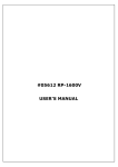
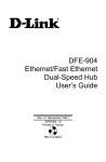
The Front Panel
Thirty-two (32) port 100/10Mbps N-Way Switch w/ two (2) fiber ports
Thirty-two (32) port 100/10Mbps N-Way Switch w/ one (1) fiber port
Thirty-two (32) port 100/10Mbps N-Way Switch
Twenty-four (24) port 100/10Mbps N-Way Switch w/ two (2) fiber ports
Twenty-four (24) port 100/10Mbps N-Way Switch w/ one(1) fiber port
Twenty-four (24) port 100/10Mbps N-Way Switch
Port Speeds
100/10Mbps TP Ports
Each 100/10Mbps TP port provides an Auto-Negotiation function that senses for the attached device's maximum
operating speed and automatically sets the Switch to operate at that speed. Each TP port uses RJ-45 connectors that
allow network TP cables to be easily attached or removed. Users only need to connect a network device into any TP
port and the Switch will do the rest.
100BASE-FX Fiber Port (Models with Fiber port, only):
100BASE-FX is primarily used for network backbones. The Fiber ports come with an SC connector for
attaching multi-mode optical fiber cables. A DIP switch is provided on the front panel for each fiber port so
users can manually set the 100BASE-FX port to operate in Half-Duplex (default), or forced Full-Duplex mode.
DIP Switch (Models with Fiber port, only)
The Table below lists the 100BASE-FX Port DIP Switch Settings:
DIP Switch in “Up” Position
DIP Switch in “Down” Position
100Mbps Half-Duplex
100Mbps Full-Duplex
Crossover Connector
Each model supports a Crossover function. The Crossover function is used for Uplinking to a standard port on
another Hub using normal TP cable.
Warning: You cannot use the Crossover connector and the attached regular connector at the same time.
Cabling
10Mbps – Category 3, 4, or 5 TP cabling can be used for transmitting data at 10Mbps or 20Mbps on
10BASE-T networks.
100Mbps – Only Category 5 TP cabling can be used for transmitting data at 100Mbps or 200Mbps on
100BASE-TX networks.
Port Type
Cable Type
Connector
10BASE-T
Category 3, 4 or 5 TP
RJ-45
100BASE-TX
Cat. 5 TP
RJ-45
100BASE-FX
62.5/125 um multimode fiber cable
SC
Note: Category 5 TP cable should be used whenever installing new TP cabling.
Status LEDs
These Switches come with a complete range of LEDs. The table below lists each LEDs name, color and a brief
description of its function.
•
One (1) for power On/Off
•
One (1) per port for Link/Activity
•
One (1) per port for Full-Duplex/Collision
NAME
COLOR
POWER
(PWR)
Green
• Lit: Power "On"
• Unlit: Power “Off”
FUNCTION
LINK/ACT
Green
• Lit: When the port has a valid physical connection (Link) with another
device.
• Blinks: When the port is sending or receiving data (Activity).
FD/COL
Amber
• Lit: When port is set to Full-Duplex mode.
• Blinks: When a collision is detected, when the port is in Half-Duplex
mode.
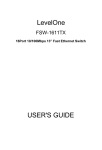
The Rear Panel
On/Off ("Reset") Switch
The power On/Off switch is located on the far right of the rear panel - next to the power connector.
To Reset the Switch, turn the power switch "Off," then "On."
Note: The Switch must be reset when the MAC address table needs to be rebuilt.
Power Socket
The Power Socket is designed to be used with the power cord included in the product package.
a) Attach the female end of the cord to the power connector on the back panel.
b) Attatch the male end of the cord to a grounded power outlet.
Fan
Important: Please keep the fan area clear, so that the cooling function is not impaired.
3.
INSTALLATION
Every model is "Plug & Play." They do NOT require software configuration. Users can immediately use any
of the features of this product simply by attaching the cables and turning on the power.
To Locate The Switch On A Desktop,
a) Attach the four (4) rubber feet included in the product package to the bottom of the Switch, one in each
corner.
b) Place the Switch on a clean, flat desk or table top close to a power outlet.
c) Plug in all network connections and the power cord
d) Turn the power switch to "On."
Rackmount Placement
These Switches can be mounted in an EIA standard-sized 19-inch rack.
1. Attach one (1) rackmounting bracket on each side of the Switch’s front panel with the provided
screws.
2. Use the other provided screws to secure each Switch to the
rack.
4. HELPFUL SUGGESTIONS
Prior to Installation
Before installing these Switches and connecting network devices, it is important to plan the network's layout.
Things you should consider include:
• Dedicated Bandwidth: File servers and other high-traffic hardware improve their performance if they have their
own dedicated 10Mbps or 100Mbps bandwidth.
• Full-Duplex: Determine which devices support Full-Duplex connections.
• Fast Ethernet: Make sure rules for cable lengths and categories are followed. 100BASE-TX and 100BASE-FX
•
•
have different rules for cable and distance.
Auto-Negotiation: Devices with different speeds may be easily swapped when the other end of the cable is
fixed to a port with Auto-Negotiation.
Crossover Uplink: These Switches can be Uplinked to another Hub using the Crossover function.
• Remember - If you are using the last TP port’s Crossover port, you cannot use the last TP port’s regular port. If
you use both of the last port's ports at the same time your Hub will not operate properly.
Half- and Full-Duplex
These Switches support both Half- and Full-Duplex modes for 10BASE-T and 100BASE-TX.
• In Half-Duplex mode data cannot be transmitted and received at the same time. Attached devices must
finish transmitting data before they can receive data.
• In Full-Duplex mode data can be transmitted and received at the same time.
However:
a) Full-Duplex transmission is only possible between two devices with a dedicated link (e.g., Switch-Switch,
Switch-PC)
b) Both devices must have Full-Duplex capability
c) Both devices must be set to Full-Duplex (e.g. Auto-Negotiation – Auto-Negotiation, Non-Auto-Negotiation
to Non-Auto-Negotiation)
•
The 100BASE-TX/10BASE-T ports on these Switches detect and set the line's operating mode by using
their Auto-Negotiation function.
Fast Ethernet
100BASE-TX is called "Fast Ethernet." In Fast Ethernet (100Mbps) data travels ten times faster than in
traditional Ethernet (10Mbps).
Below is a list of the cable types and connectors supported by the Switch for 10BASE-T and 100BASE-TX
networks.
Port Type
Cable Type
Connector
10BASE-T
Category 3, 4 or 5 TP
RJ-45
100BASE-TX
Cat. 5 TP
RJ-45
Note: If your 10BASE-T network currently uses Cat. 5 TP cabling, you can instantly upgrade the network
to a 100BASE-TX network by changing network devices.
Auto-Negotiation
Every 100/10Mbps dual speed port on these Switches has a built-in "Auto-Negotiation" function. This
technology automatically sets the best possible bandwidth as soon as a connection is established with
another network device (usually at Power “On” or Reset). This is capability is achieved via the Switches
Auto-Negotiation function that automatically detects the modes and speeds the second (attached) device is
capable of.
Evaluating Auto-Negotiation Capability:
If the attached device is:
100Mbps, no Auto-Negotiation
100Mbps, with Auto-Negotiation
10Mbps, no Auto-Negotiation
The Switch Will Automatically Set Its TP Ports to Operate At:
100Mbps Bandwidth (100BASE-TX, Half-Duplex)
200Mbps Bandwidth (100BASE-TX, Full-Duplex)
10Mbps Bandwidth (10BASE-T, Half-Duplex)
10Mbps, with Auto-Negotiation
20Mbps Bandwidth (10BASE-T, Full-Duplex)
Helpful Warning: If the attached device is set to a fixed mode (ex: Forced Full-Duplex) it will not operate
as an Auto-Negotiation device.
MAC Address Table
Every Ethernet data packet includes both source and destination addresses. This 6-byte ID is called the
MAC (Media Access Control) Address.
These Switches can automatically learn and store MAC addresses. However, the MAC address table is
volatile: it disappears when the Switch is powered “Off” or reset.
Note: When the network needs reconfiguration, we recommend turning off the power first. After all
nodes have been moved, turn the Switch back "On" to rebuild the internal MAC address table.
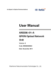
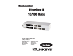
5. SAMPLE APPLICATION
The optimal application for these Switches is as a "big pipe" backbone interconnecting file servers with
bandwidth-hungry workgroups, departments, and offices.
6. TROUBLESHOOTING
I.
Link LED does not lit after cable is connected to the port.
Verify that the other end of the cable is connected to a device that is powered on and on-line.
For TP cable connection to another hub, verify that only one end of the cable is connected to a
“Crossover” port.
II. 100BASE-TX port Link LED is lit, Collision LED is blinking, but traffic is irregular.
Check that the attached device is not set to dedicated Full-Duplex. (Some devices use a physical
or software switch to change Duplex modes. Auto-Negotiation may not recognize this type of
Full-Duplex setting).
Remember: For any change to DIP switch settings to take effect, the PowerSWITCH must be turned
“Off”, then “On” again.
ALWAYS CHECK THAT:
Cable and link distances are within the network's specifications
Overall network diameters are within the network's specifications
You are not using the Crossover connector and the attached regular connector at the same time.
7. PRODUCT SPECIFICATIONS
Models
Standards
Ports
Media Support
Bandwidth
32 PORTS 100BASE-TX SMART
SWITCH
•
10BASE-T IEEE 802.3
31 PORTS 100BASE-TX + 1 PORT
100BASE-FX SMART SWITCH
30 PORTS 100BASE-TX + 2 PORTS
100BASE-FX SMART SWITCH
•
100BASE-TX IEEE 802.3u
•
IEEE 802.3x Flow Control for Full-Duplex operation
•
Thirty-two (32) 100BASETX/10BASE-T
•
Thirty-one (31) 100BASE-TX/10BASE-T •
•
One (1) 100BASE-FX -
•
•
10BASE-T Category 3, 4 or 5 TP
100BASE-TX Category 5 TP
•
10BASE-T Category 3, 4 or 5 TP
•
•
100BASE-TX Category 5 TP
100BASE-FX 62.5/125 um multimode fiber cable
•
100BASE-TX - 200/100
•
100BASE-TX - 200/100Mbps
•
10BASE-T - 20/10Mbps
•
100BASE-FX - 200/100Mbps
•
10BASE-T - 20/10Mbps
Forwarding/Filtering •
Rate
•
•
Thirty (30) 100BASE-TX/10BASE-T
Two (2) 100BASE-FX -
148,800 packets/second per port @ 100Mbps, max.
14,880 packets/second per port @ 10Mbps, max.
•
11 µsec @100Mbps, minimum
•
75 µsec @ 10Mbps, minimum
MAC Addresses
•
1,031 six (6)-byte entries maximum, self-learning
Buffer Memory
•
8 Mbyte
Duplex Modes
•
TP ports have 100/10Mbps
Full/Half-Duplex AutoNegotiation function
•
TP ports have 100/10Mbps Full/Half-Duplex Auto-Negotiation
•
Fiber ports set to Half or Forced Full-Duplex mode via a DIP switch
•
Port 32 has an extra connector
that supports a Crossover
function
•
Port 31 has an extra connector that
supports a Crossover function
•
Ports 15 & 30 each have an extra
connector for Crossover functions
•
One (1) for Power
•
One (1) for Power
•
One (1) for Power
•
One (1) to set Fiber port to Half- or
Full-Duplex
•
Two (2) to set Fiber ports to Half- or
Full-Duplex
•
One (1) per port for Full-Duplex /Collision
•
Input voltage: 100 ~ 240 +/-10% VAC/ 50 ~ 60 Hz
Latency
Crossover
Switches
LED Indicators
Power Supply
•
One (1) for Power
•
One (1) per port for Link / ACT
•
Internal full range autoswitching
Power Consumption •
36.4 watt max.
Environment
•
•
•
Operating Temp: 0° ~ 45°C (32° ~ 113°F)
Storage Temp : -20° ~ 70°C (-4° ~ 158°F)
Humidity
: 10% ~ 90% non-condensing
Dimensions
•
442 x 185 x 44 mm (17.40 x 7.28 x 1.73 inches)
Models
Standards
Ports
Media Support
•
24 PORTS 100BASE-TX SMART
SWITCH
10BASE-T IEEE 802.3
23 PORTS 100BASE-TX + 1 PORT
100BASE-FX SMART SWITCH
•
100BASE-TX IEEE 802.3u
•
IEEE 802.3x Flow Control for Full-Duplex operation
•
Twenty-four (24) 100BASE-TX/10BASE- •
T
•
•
•
10BASE-T Category 3, 4 or 5 TP
100BASE-TX Category 5 TP
Twenty-three (23) 100BASE-TX/10BASE-T
One (1) 100BASE-FX
22 PORTS 100BASE-TX + 2 PORTS
100BASE-FX SMART SWITCH
•
Twenty-two (22) 100BASETX/10BASE-T
•
Two (2) 100BASE-FX
•
10BASE-T Category 3, 4 or 5 TP
•
•
100BASE-TX Category 5 TP
100BASE-FX 62.5/125 um multimode fiber cable
Bandwidth
•
100BASE-TX - 200/100Mbps
•
100BASE-TX - 200/100/20/10Mbps
•
10BASE-T - 20/10Mbps
•
100BASE-FX - 200/100Mbps
•
10BASE-T - 20/10Mbps
Forwarding/Filtering •
Rate
•
148,800 packets/second per port @ 100Mbps, max.
14,880 packets/second per port @ 10Mbps, max.
•
11 µsec @100Mbps, minimum
•
75 µsec @ 10Mbps, minimum
MAC Addresses
•
1,031 six (6)-byte entries maximum, self-learning
Buffer Memory
•
6 Mbyte
Duplex Modes
•
TP ports have 100/10Mbps Full/Half- •
Duplex Auto-Negotiation function
•
Latency
Crossover
Power Supply
Fiber ports set to Half or Forced Full-Duplex mode via a DIP switch
•
Port 24 has an extra connector that
supports a Crossover function
•
Port 23 has an extra connector that
supports a Crossover function
•
Ports 11 & 22 each have an
extra connector for Crossover
functions
•
One (1) for Power
•
One (1) for Power
•
One (1) for Power
•
One (1) to set Fiber port to Half- or Full- •
Duplex
•
One (1) per port for Full-Duplex /Collision
•
Input voltage: 100 ~ 240 +/-10% VAC/ 50 ~ 60 Hz
Switches
LED Indicators
TP ports have 100/10Mbps Full/Half-Duplex Auto-Negotiation
•
One (1) for Power
•
One (1) per port for Link / ACT
•
Internal full range auto-switching
Power Consumption •
36.4 watt max.
Environment
•
•
•
Operating Temp: 0° ~ 45°C (32° ~ 113°F)
Storage Temp : -20° ~ 70°C (-4° ~ 158°F)
Humidity
: 10% ~ 90% non-condensing
Dimensions
•
442 x 185 x 44 mm (17.40 x 7.28 x 1.73 inches)
Two (2) to set Fiber ports to
Half- or Full-Duplex