1
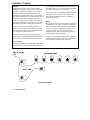
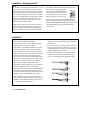
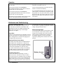
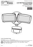
FarmTek
Sport Timing Specialists
Laser Stakes
Laser Positioning System
For Barrels and Poles
User’s Manual
FarmTek, Inc.
1000 North Hwy 78, Suite D
Wylie, TX 75098
(972) 429-0947
(800) 755-6529
Introduction
Laser Stakes mount in the ceiling of your arena to
mark barrel, pole and electric eye positions with a
beam of light. This permanent solution to marking
pattern positions makes each setup fast, easy and
accurate. Without stakes in the ground, arena drags
are quicker and more effective – especially
immediately around each barrel and pole.
Operation
The lasers are turned on and off with a small wireless remote. All lasers can be turned on/off at the
same time, or lasers can be grouped into “zones”
for more complex configurations (up to 4 zones).
The arena crew in charge of moving the barrels and
poles can carry the remote and turn the lasers on
and off as they need. This means one less thing the
busy crew in the announcer’s booth needs to worry
about.
The ability to turn the lasers on only while needed
greatly extends laser life and eliminates the chance
the laser might distract horses or riders during a
run. The lasers automatically shut off after five
minutes if the arena crew forgets to turn them off.
FCC and Industry Canada Information
This device complies with Part 15 of the FCC
Rules. Operation of this device is subject to the
following two conditions:
1) This device may not cause harmful interference, and
2) this device must accept any interference received, including interference that may cause
undesired operation.
This equipment has been tested and found to comply with the limits for a Class B digital device,
pursuant to Part 15 of the FCC Rules. These limits
are designed to provide reasonable protection
against harmful interference when the equipment
is operated in a residential installation. This
equipment generates, uses, and can radiate radio
frequency energy and, if not installed and used in
accordance with the instruction manual, may
cause harmful interference to radio communications. However, there is no guarantee that interference will not occur in a particular installation.
© 2012 FarmTek, Inc.
If this equipment does cause harmful interference
to radio or television reception, the user is encouraged to try to correct the interference by one or
more of the following measures: (1) Reorient or
relocate the receiving antenna. (2) Increase the
separation between the equipment and the receiver. (3) Consult the dealer or radio/TV technician for help.
CAUTION: Changes made or modifications not
expressly approved by the party responsible for
FCC compliance of this equipment could void the
user’s authority to operate the equipment.
Installation – Planning
Overview
Installation of the Laser Stakes system requires
running a low voltage DC power wire between each
laser. The required two-conductor wire is readily
available at stores like Home Depot and Lowes.
Connections are made with an easy to use terminal
block. Each terminal block provides positions for an
incoming wire pair and an outgoing wire pair to the
next laser. To make wiring simple, the connections
are polarity-independent so you don’t have to worry
about mixing up positive and negative conductors.
Power for all lasers is provided by a single AC
adapter. Wires run from the AC adapter to the first
laser, from the first laser to the second laser, from
the second laser to the third laser, etc.
Each laser easily attaches to a roof support with a
strong magnet. An adjustable ball-head mechanism
allows you to aim each laser precisely at its target.
laser should be mounted as directly above the target
as possible. However, you will be able to adjust the
final aim of the laser after it is mounted.
A flat metal surface to which the magnet can attach
is required at the locations chosen to mount the
lasers. Other mounting options are available if
required – contact us.
Wiring
The wiring run starts at the AC adapter plugged into
a standard 120 volt outlet. From there, a wire is run
to the closest laser, then from laser to laser to laser.
For more complex configurations, wiring can “T”
off from any laser to start a separate run. The
illustration below shows a typical wiring run for a
combined barrel and pole pattern.
18 gauge, two conductor speaker wire or lamp wire
should be used for wiring. This wire is available in
various lengths at Home Depot and Lowes.
Laser Locations
Choose the location in the ceiling where each laser
will be mounted. For best positioning accuracy, the
Typical Wiring Example
© 2012 FarmTek, Inc.
Installation – Planning (cont’d)
Zones
Out of the box, the lasers respond to all four rows of
buttons (zones) on the wireless remote. For more
control, lasers can be set to respond only to specific
rows (zones) on the remote. For example, the three
lasers for the barrel pattern could be set to respond
only to zone 1 button presses on the remote. The six
pole lasers could be set to respond only to zone 2
button presses. If needed, lasers can be set to respond to multiple zones as well.
A DIP switch on the back of the laser is used to set
which remote control zones the laser responds to.
There is one slide switch per zone. If the switch is
slid up towards the large zone numbers printed on
the circuit board, the laser responds to that zone. If
the switch is slid down towards the word “Zone,”
the laser does not respond to that
zone. For the example illustrated
on the right, the laser will respond
to button presses for zones 1 and 2,
but not to presses for zone 3 or 4.
If all four zones are set to “off” (down), then the
laser is on any time power is applied. This can be
used for special applications where the remote is not
used and the lasers are turned on and off with a
power switch.
Installation
After planning is complete, install the wiring and the
lasers. Note these important guidelines:
• Leave about one foot of extra wire coming into
and leaving from each laser location.
• Strip about ¼” of insulation from the wire ends
for proper installation into the terminal blocks.
• The terminal block is divided into an IN pair of
contacts and an OUT pair of contacts. The two IN
contacts are electrically equivalent to the two
OUT contacts, so it does not really matter which
wire pair is connected to the the IN contacts and
which pair is connected to the OUT contacts.
• To prevent possible damage, do not plug the AC
adapter into an outlet until all wiring is complete
and checked.
• If you want to check a section of lasers before all
lasers are wired, make sure there are no sections
of unterminated wires connected to any laser that
might accidentally cause a short.
• Complete the installation by aiming each laser
exactly at the desired position for each barrel,
pole, etc., and tightening the adjustment knob.
• Wire pairs are polarity independent – the
conductors can be swapped either way within the
IN pair or within the OUT pair of contacts.
OK
• Wire pairs must be connected to either the IN pair
of contacts or the OUT pair of contacts. A wire
pair must never be split across an IN contact and
an OUT contact (see illustration on the right).
OK
• More than one wire pair can be connected to a
pair of terminal contacts. See the “Typical Wiring
Example” where the wire run for the pole lasers
T’s off from the first barrel laser.
© 2012 FarmTek, Inc.
NO!
NO!
Operation
At the start of the day, plug the AC adapter into a
120 volt outlet.
pressing and holding buttons for about a second
each time to turn lasers on or off.
To turn a laser group on, press and hold the
corresponding ON button on the remote for about a
second (count “one-one thousand”).
Lasers will automatically turn off after about five
minutes if not turned off maually.
To turn a laser group off, press and hold the
corresponding OFF button on the remote for about a
second (count “one-one thousand”).
Just because you feel a button “click” does not mean
the laser will respond. Become accustomed to
It is recommended that the lasers be turned on only
while needed to set the barrel or pole pattern. Have
the grounds crew carry the remote so they can turn
the lasers on and off as needed. This leaves one less
thing for the busy folks in the announcer’s booth to
worry about.
Maintenance and Troubleshooting
Remove AC Power When Not In Use
When not in use, unplug the AC adapter from the
120 volt outlet (or cut power to the outlet). This
extends the life of the AC adapter and reduces the
chance that an electrical surge or storm might
damage the AC adapter.
System Reset
If some or none of the lasers are responding, reset all
lasers by removing the AC adapter from the 120 volt
outlet, waiting about 15 seconds, then plugging the
AC adapter back into the outlet.
Changing the Remote Control Battery
The remote control unit utilizes a standard CR2032
lithium button cell. In normal use, it will provide
one to two years of operation. To replace the battery,
remove the access cover by pressing down firmly on
the label area and sliding it off. Once the unit is
open, remove the battery by sliding it from beneath
the holder. Replace it with the same type of battery
while observing the polarity shown to the right.
AC Adapter Voltage Check
If none of the lasers are responding even after a
system reset, use a volt meter to verify 12 volts is
present across the screw terminals on the AC adapter
when plugged into AC power. If not, unplug the AC
adapter, remove the wires from the screw terminals,
plug the AC adapter back into the outlet, and test for
© 2012 FarmTek, Inc.
12 volts again. If 12 volts is present after removing
the wires, there is probably a wiring short in the low
voltage wiring between the lasers.
Remote Control DIP Switch
A ten position DIP switch is located under a small
cover on the back of the wireless remote. These
switches are not related to the “Zone” switches
inside each laser and should not be changed. If
accidentally changed, you can restore proper
operation by sliding all ten switches to the “ON”
position.