1
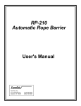
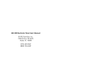
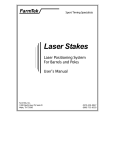
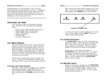
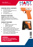
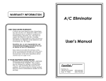
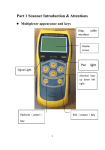
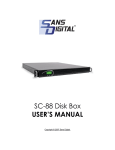
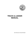
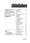
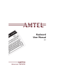
RP-250
Electric Eye Barrier
(For MD-300 Electronic Timer)
User's Manual
Rev 4/96-AB
FarmTek
FarmTek, Inc.
5113 Heritage Ave.
Sachse, TX 75048
(214) 495-6529
(800) 755-6529
RP-250 Electric Eye Barrier User's Manual
Congratulations on your purchase! Your new
RP-250 Electric Eye Barrier should provide
years of trouble-free service. The RP-250 is an
option for the MD-300 Timer. Please read the
MD-300 Electronic Timer User's Manual and become familiar with normal operation of the
timer before attempting to use the Electric Eye
Barrier. Allow plenty of time before your first
event to set up and become familiar with the
RP-250 Electric Eye Barrier.
Equipment Provided
The following equipment is provided with the
RP-250 Electric Eye Barrier:
• Reflective electric eye, reflector and
mounting hardware.
• 125 foot cable to connect the reflective
electric eye to the MD-300 Timer (can be
extended in 125 foot increments with the
standard MD-300 extension cord, part
number OE-225).
INTRODUCTION
The RP-250 Electric Eye Barrier is a short
range, reflective electric eye used with the MD300 Timer to support roping events. The RP250 replaces cumbersome rope barriers with an
invisible infrared light beam to simplify and
speed up your roping events.
STEP-BY-STEP SETUP INSTRUCTIONS
Here's how it works:
1) Set up electric eye for steer score line.
Place the MD-300 Electric Eyes on opposite
sides of the steer chute to form an invisible
score line at the desired distance in front of the
chute. Adjust the height of the electric eyes to
ensure the beam is broken by the steer's body-not its legs. You can mount the eyes just a few
feet apart at the end of a runway or tunnel
which forces the steer through the eyes, or you
can mount the eyes on the tripods such that
the beam extends across the rider's boxes as
well as the steer release chute. (Once the beam
has been broken by the steer, further interruptions of the beam are ignored.)
• The MD-300 electric eyes are set up in or
across the arena to form an invisible score
line that the steer runs through to start
the timer. The eyes are set as far in front
of the steer release chute as desired.
(Optionally, an additional RP-250 Electric
Eye Barrier can be used instead of the MD300 Electric Eyes to form the steer score
line. This is discussed in more detail in a
following section.)
• An RP-250 Electric Eye Barrier is set up
across the rider's box.
• When the steer's light beam is broken, the
timer automatically resets to zero and
starts timing.
• If the RP-250 light beam across the rider's
box is broken before the steer's light beam
is broken (i.e., a "broken barrier"), the MD300 Timer sounds the horn to flag the
fault. In addition, the timer console displays the fault to ensure the timekeeper is
aware of the broken barrier.
• Once the steer's beam has been broken,
further interruptions of the steer's infrared
light beam are ignored until after the timer
has been manually stopped. This allows
the steer's beam to extend across the rider's box(es) if desired.
• When the judge lowers the flag, the timer
operator stops timing by pressing the
STOP button on the MD-300 Timer console. The rider's final time is displayed.
The timer is now ready for the next rider.
©1996 FarmTek, Inc.
A typical arena setup using the RP-250 is
shown in Figure 1. The following steps outline
how to configure the MD-300 Timer, the OE200 Automatic Horn and the RP-250 Electric
Eye Barrier for roping operation.
2) Set up RP-250 eye on rider's box.
Place the reflective electric eye and reflector
provided with the RP-250 Electric Eye Barrier
on opposite sides of the rider's box at the desired location for the barrier. Adjust the height
of the electric eye to ensure the beam is broken
by the horse's body--not its legs.
3) Connect cables to electric eyes.
WITH THE TIMER CONSOLE "OFF" (unplugged
from electricity), connect a 125 foot cable from
the RECEIVER jack on the timer console to the
MD-300 Receiver electric eye. Connect a second 125 foot cable from the AUX jack on the
timer console to the short cable exiting from
the RP-250 electric eye. Make sure all plugs are
fully inserted into the jacks and couplers.
4) Connect horn.
If you have the OE-200 Automatic Horn, plug
the 25 foot gray cord from the horn into the
Page 1
RP-250 Electric Eye Barrier User's Manual
HORN jack on the timer console. Plug the
power cord from the horn into a 110 volt outlet.
If instead of the OE-200 Horn, you have a
scoreboard with a built-in horn, connect the
data cable from the scoreboard into the DISPLAY jack on the timer console.
5) Turn on timer console.
Turn on the timer console by plugging the A/C
adapter into a 110 volt outlet and into the
POWER jack on the rear of the timer console.
The unit should power on and show a time of
zero seconds. If not, unplug the unit for a few
seconds and plug it back in.
6) Select "Roping 2" event type.
Unless you requested your timer to power up
into the Roping 2 event type, you must manually select the Roping 2 event type at this time.
Press the SETUP button. The display will show
"Good" or "Bad." At this time, it does not matter which one it shows. Press the NEXT button
(labeled in blue to the right of the key) a few
times until "Rope 2" is displayed. When "Rope
2" is displayed, press the SELECT OPTION button to select the Rope 2 event type. The display
will show "done" for a second, then return to
timing mode showing a time of zero seconds.
7) Align electric eyes.
Turn the switch on the back of the MD-300
Transmitter electric eye "on." The red battery
indicator light should begin blinking to let you
know the Transmitter is operating. Align the
MD-300 Electric Eyes by ensuring they are
pointed directly at each other when sighting
down either line on the top of the eye and down
the crack on the side of the eye.
Align the RP-250 reflective electric eye by tilting
it up and down and left and right while watching the green indicator light on the top of the
electric eye. When the green light turns on, the
eye is aligned. Note the up and down positions
and the left and right positions when the indicator light turns off. Position the eye midway
between these points to ensure the best possible alignment. (The red light comes on when
the eye is aligned and there is a 2 to 1 safety
margin--a good strong signal).
8) Check eye alignment from console.
Press the SETUP button on the timer console.
"Good" or "Bad" is displayed indicating the
alignment of the electric eye plugged into the
RECEIVER jack. This is the steer's beam. The
©1996 FarmTek, Inc.
alignment status should show "Good." Have
someone break the steer's beam. The display
should switch to "Bad" as long as the beam is
broken and return to "Good" as soon as the
beam is no longer broken.
Press the NEXT button to display the alignment
status of the electric eye plugged into the AUX
jack. This is the rider's box eye. The display
should read "Good A." (The "A" indicates this is
status for the AUX jack.) Have someone break
the rider's beam. The display should switch to
"Bad A" as long as the beam is broken and return to "Good A" as soon as the beam is no
longer broken.
Note: You can go back and forth between the
alignment status of the two eyes by pressing
the PREV key to go backward and the NEXT
key to go forward.
9) Verify system operation.
Press the EXIT SETUP button to stop checking
the alignment status of the eyes. To check system operation, have three people ready: One to
break the steer's beam, one to break the rider's
beam and a third person to operate the timer
console. Since the eyes are set to ignore breaks
which are too short to be cattle or a horse, it is
best to walk through the beams when testing
them. First, break the steer's beam before
breaking the rider's beam. When the steer's
beam is broken, the timer will reset to zero and
begin counting. When the rider's beam is broken following the steer's beam, nothing else will
happen. Stop timing by pressing the START/
STOP button.
For the second test, break the rider's beam just
prior to breaking the steer's beam (i.e., broken
barrier condition). The steer's beam must be
broken within two seconds of breaking the rider's beam. When the rider's beam is broken
first, the horn will sound. Normal timing will
still occur when the steer's beam is broken.
Stop timing by pressing the START/ STOP button. The word "Header" should flash periodically over the time to alert the timekeeper that
there was a broken barrier on the run (older
timers flash the word "Fault"). No action is required to remove the flashing "Header" message. It will be removed when the next steer is
released.
THE TIMER IS READY FOR ROPING!
Page 2
RP-250 Electric Eye Barrier User's Manual
OE-200
Automatic Horn
To HORN jack
To RECEIVER jack
To AUX jack
MD-300 Timer
Console
MD-300
Receiver
RP-250
Reflective Eye
HEADER'S
BOX
RP-250
Reflector
STEER CHUTE
HEELER'S
BOX
MD-300
Transmitter
Figure 1, Typical Arena Setup
ROPING EVENT OPERATION
Once set up, using the RP-250 Electric Eye
Barrier for roping events is simple. When the
steer breaks its beam, the timer automatically
resets to zero and begins timing. When the
judge lowers the flag, the timer operator stops
timing by pressing the START/STOP key on the
MD-300 Timer console. The display shows the
rider's time. If the rider breaks out before the
steer crosses the score line to start the timer,
the horn is sounded to flag the fault and the
console flashes "Header" on its display to alert
the timer operator of the broken barrier (older
©1996 FarmTek, Inc.
timers may display the word "Fault"). The
timer is now ready for the next team. No reset
or "ready" operation is required. Even the
flashing "Header" message is automatically removed when the next steer starts the timer.
Note: If you prefer the timer and electric eyes to
remain disabled in between riders until the
timekeeper manually "resets" the timer, the
MD-300 can support this. Contact FarmTek for
assistance.
Page 3
RP-250 Electric Eye Barrier User's Manual
Broken Barrier Detection
Detection of a broken barrier is slightly more
complex than mentioned thus far. With the
MD-300 Timer, a broken barrier occurs when
the rider breaks his beam less than two seconds before the steer breaks its beam. If the
rider's beam is broken more than two seconds
before the steer's beam is broken, it is not considered a broken barrier. If desired, you can
change the two second "window" between the
rider and steer to any time value you require.
Contact FarmTek for assistance.
Broken Barrier Example
As the steer is released, the rider breaks his
beam a fraction of a second before the steer
breaks its beam. Since the rider's beam
was broken less than two seconds before
the steer broke its beam, this is considered
a broken barrier.
Not a Broken Barrier Example
A rider front loads the box and breaks his
beam as he enters. Fifteen seconds later
the steer is released and breaks the steer's
beam. The rider's beam was broken before
the steer's beam, but this is obviously not a
broken barrier. The timer does not consider this a broken barrier since the rider's
beam was broken more than two seconds
before the steer broke its beam.
When a broken barrier is detected, the timer
console will flash the word "Header" on its display after the timer is stopped for the current
rider (older timers may flash the word "Fault").
The flashing message is automatically erased
when the timer starts for the next rider--no
timer operator action is required.
Horn Indication of a Broken Barrier
The horn can be configured to sound in two
different ways. Configuration (1) listed below is
the default configuration of the MD-300 Timer
when shipped from the factory. If desired, you
can change the configuration to match item (2).
Call FarmTek for assistance.
1) Sound the horn anytime the rider's beam is
broken and the timer is not running (i.e.,
the steer has not broken its beam and
started the timer). The advantage of this
configuration is the confidence provided by
hearing the horn each and every time the
rider's beam is broken while the timer is
stopped. The disadvantage is that the horn
©1996 FarmTek, Inc.
sounds even when there is not a broken
barrier. For example, if the timer is
stopped, the horn will sound as the rider
breaks the beam to front load the rider's
box.
2) Sound the horn only when a broken barrier
is detected as outlined previously. The advantage of this configuration is that the
horn sounds only when there is a broken
barrier. Front loading of the rider's box, for
example, can take place without the horn
sounding. The disadvantage of this configuration is the confusion it may afford some
riders. For example, when the rider accidentally breaks his beam before calling for
the steer, the horn does not sound because
the steer does not immediately follow and
break its beam. The rider then questions
whether "the thing is working."
Note that console display of a broken barrier is
independent of the two horn configurations and
always follows the rules outlined previously for
detection of a broken barrier.
Setup Notes: Timer Console
As mentioned in the step-by-step instructions,
when the MD-300 Timer console is first turned
on, the barrel racing event type is automatically
selected. To use the MD-300 and RP-250
Electric Eye Barrier for roping events, the "Rope
2" event type must be selected. Details on this
procedure are provided in the Timer Setup - Selecting Event Type section of the MD-300 Electronic Timer User's Manual. Note: If you would
prefer to have the "Rope 2" event type automatically selected whenever the MD-300 Timer
console is turned on, you can change this.
Contact FarmTek for assistance.
The default timing format for roping is counting
up in seconds with 0.001 second resolution. In
reality, 0.001 second resolution is meaningless
for roping events when you consider the reaction time of the judge and the timer operator
watching the judge. If desired, you can change
the default time format for roping events to
0.01 second resolution. See the Timer Setup Time Format and Counting Direction and the
Timer Setup - Setting Event Defaults sections of
the MD-300 Electronic Timer User's Manual for
information on how to change the time format.
Or, feel free to contact FarmTek for assistance.
If you desire the horn to sound for a shorter or
longer period when the barrier is broken, you
Page 4
RP-250 Electric Eye Barrier User's Manual
can change this. Contact FarmTek for assistance.
Setup Notes: Steer Score Line
There are several possibilities for forming the
score line broken by the steer to start the timer.
The score line can be formed using the MD-300
Electric Eyes, or an additional RP-250 Electric
Eye Barrier can be used. If you are using an
RP-250 to form the score line, your MD-300
Timer Console should have been configured at
the factory to use the RP-250 electric eye instead of the MD-300 Electric Eyes. If not, you
can change this. Contact FarmTek for assistance.
Following are some notes if you are using the
MD-300 Electric Eyes to form the score line
broken by the steer:
1) You can mount the eyes just a few feet
apart at the end of a runway or tunnel
which forces the steer through the eyes.
The 1/4 - 20 thread in the bottom of the
electric eyes is a convenient way to mount
each eye. Note: Never screw more than
about 1/4" of thread into the electric
eyes or severe damage can occur!
2) The electric eyes can be mounted on the
tripods such that the beam between the
eyes extends across the rider's boxes as
well as the steer release alley. (Once the
beam has been broken by the steer, further
interruptions of the beam are ignored.)
With this placement, the steer can run free
when released--as they do when using a
neck rope--rather than forcing them down a
tunnel. To protect the tripods and eyes
from damage, they can be housed inside a
cage or barrel with cutouts for the light
beam, or placed completely outside the
arena.
If using an additional RP-250 Electric Eye Barrier to form the score line instead of using the
MD-300 Electric Eyes, place the reflective electric eye and reflector on opposite sides of the
steer alley to form an invisible score line at the
desired distance in front of the release chute.
Adjust the height of the electric eye and reflector to ensure the beam is broken by the steer's
body--not its legs. See Figure 2 for a sample
arena setup using the RP-250 for the steer
score line.
©1996 FarmTek, Inc.
The maximum range of the RP-250 electric eye
is about 20 to 30 feet. Because of the limited
range, the score line must generally be formed
in one of the two ways outlined below:
1) You can mount the electric eye and reflector
just a few feet apart at the end of a runway
or tunnel which forces the steer through
the light beam. See Figure 2.
2) The electric eye can be mounted on a stand
or pole to the outside of the header's box
and the reflector mounted on a panel or
fence on the heeler's side of the steer release such that the beam extends across
the header's box as well as the steer release
alley. (Once the beam has been broken by
the steer, further interruptions of the beam
are ignored.) With this placement, the steer
can run free when released--as they do
when using a neck rope--rather than forcing them down a tunnel.
Reflective Electric Eye Information
The RP-250 Electric Eye Barrier is supplied
with a metal mounting bracket to ease installation and alignment of the eye. The bracket can
be left permanently attached to your fence and
the eye installed into the bracket just before
use.
One way of attaching the reflective electric eye
to the mounting bracket is shown in Figure 3.
(Note: your bracket may not exactly match the
one shown). The bracket allows two axis adjustment of the eye as required for alignment.
Optionally, the eye may be mounted without
the bracket using two long screws through the
body of the eye, also as shown in Figure 3.
The maximum range of the RP-250 Electric Eye
Barrier is dependent on a number of factors
including how bright it is outside, the amount
of dust suspended in the air and how dirty the
electric eye and reflector are. The eye should
easily reach across the rider's box in most circumstances. Range can be extended by using
additional reflectors. A second reflector will
add another three to five feet in range. When
using more than one reflector, it is best to place
the second reflector directly above or below the
original reflector. This keeps the score line or
barrier line as narrow as possible.
Page 5
RP-250 Electric Eye Barrier User's Manual
OE-200
Automatic Horn
To HORN jack
To RECEIVER jack
To AUX jack
MD-300 Timer
Console
RP-250
Reflective Eye
HEADER'S
BOX
RP-250
Reflector
STEER CHUTE
HEELER'S
BOX
RP-250
Reflective Eye
RP-250
Reflector
TUNNEL,
PANELS, ETC.
Figure 2, Using an RP-250 for Steer Score Line
Trouble Shooting
Following are some steps to assist you in resolving problems you may encounter.
This way, when the cords are pulled, the junction point is not affected.)
1) Unplug timer, check connectors.
Unplug the power connector from the MD-300
Timer Console. While the power is unplugged,
verify that connectors are fully inserted into the
electric eyes and into the timer console. Make
sure the cords are fully inserted into the cableto-cable coupler connected to the RP-250 electric
eye. (Two cords are easily separated at the
coupler. Any sort of strain relief which prevents stress on the coupler is very beneficial.
For example, bind the two joining cords to the
fence such that there is slack at the junction
point and the junction hangs down slightly.
2) Plug in timer, re-select Roping 2 event.
Perform steps 5 and 6 of the step-by-step setup
instructions to turn the timer back on and reselect the Roping 2 event type. Once the timer
is back on and Roping 2 is selected, do not plug
or unplug any of the cords. If you need to disconnect cords, turn the timer off first.
©1996 FarmTek, Inc.
3) Manually test horn.
You can verify that the horn is operational by
manually sounding the horn. This is done by
pressing the SETUP button while holding down
the PREVIOUS TIME button (the PREVIOUS
Page 6
RP-250 Electric Eye Barrier User's Manual
TIME button is used like the SHIFT key on a
typewriter). Note that the horn sounds for as
long as the SETUP button is pressed. On older
timers, the horn is sounded by quickly pressing
the PREVIOUS TIME button twice (within less
than a second). The horn then sounds for
about two seconds.
of the electric eyes. Note whether the alignment light on the electric eye "agrees" with the
alignment status displayed on the console. For
example, when testing the rider's box eye, if the
alignment light on the electric eye is on, then
the console alignment status should read
"Good A." When the alignment light goes off,
the status on the console should show "Bad A."
4) Verify electric eye alignment.
Perform steps 7 and 8 of the step-by-step setup
instructions to align and check the alignment
Figure 3, RP-250 Mounting
©1996 FarmTek, Inc.
Page 7