1
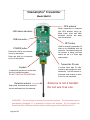
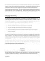
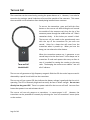
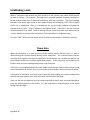
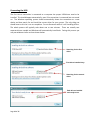
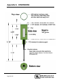
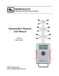
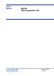
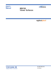
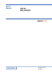
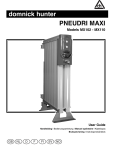
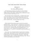
TelemetryPro® Transmitter
User Manual
Rev 2.0
May 10, 2015
www.multitronix.com
email: [email protected]
Limitation of Liability
Multitronix LLC has exercised reasonable care in the design and manufacture of this product. Each one
is carefully tested prior to shipment. However, the use or application of this product is beyond the
control of Multitronix LLC and due to the nature of electronic devices, and the applications and
environments applied to them, the possibility of failure or malfunction cannot be completely eliminated.
Therefore, the buyer assumes all responsibility and uses this product at their own risk. By using this
product the user agrees to indemnify and hold harmless Multitronix LLC and its officers, agents and
assigns from any and all liability, losses, damages, costs, claims, judgments, actions, and demands arising
out of the use of this product, claimed on account of, or in any way predicated upon loss or damage to
property, or injuries to or the death of any and all persons. If you do not agree with this limitation of
liability then do not use this product.
Revision History
Rev
1.0
1.1
1.2
1.3
2.0
Date
June 26, 2014
June 28, 2014
Nov. 10, 2014
Dec. 3, 2014
May 10, 2015
Description
Initial Release
Minor cleanup.
Added section about establishing a link.
Added section describing three digit transmitter ID codes.
Updated document format to match receiver.
The information in this document is subject to change without notice. For the most recent version of
this document visit: www.multitronix.com
Multitronix LLC reserves the right to change, improve or obsolete its products without prior notice.
TelemetryPro® is a registered trademark of Multitronix LLC
Copyright © 2015
Multitronix LLC
All Rights Reserved
Page 2 of 17
TelemetryPro® Transmitter
Model Mx110
GPS antenna
LED status indicators
USB connector
Mount transmitter in nosecone
with GPS antenna facing up.
Keep metal, wires and other
electronic devices well away
from this antenna!
SET button
POWER button
Press and hold for two seconds
to turn-on transmitter.
Press and hold for six seconds
to turn-off transmitter.
Used for changing transmitter ID
code to be compatible with old
receivers. Not needed unless an
old receiver is being used that
cannot be set to a three digit
code number.
Transmitter ID code
Eyebolt
If transmitter gets stuck in a tube then
pull it out using this eyebolt.
DO NOT PULL ON THE ANTENNA!
Downlink antenna
Keep metal, wires and other electronic
devices well away from this antenna!
A unique three digit ID code
number is pre-assigned to each
transmitter. Set the receiver to
this same code number in order
to link it to the transmitter.
Antenna is not a handle!
Do not use it as one.
WARNING: Do not attempt to remove the downlink antenna. The transmitter can be
permanently damaged if it is powered-on without the antenna. Do not operate the
transmitter with a different antenna without written approval from Multitronix LLC.
Page 3 of 17
Safety Warnings
1. The transmitter comes with a Li-ion battery already installed. Never attempt to use a
different type of battery other than the one Multitronix provides. Doing so will run a
significant risk of damaging the transmitter and possibly even starting a fire.
2. The transmitter has a built-in charger. Never attempt to charge the Multitronix supplied
battery on a charger other than the one built into the transmitter. Doing so runs a
significant risk of fire danger. The battery may get hot, catch fire or even explode.
3. Discontinue use if the battery is ever damaged, leaks fluid, feels hot, has an odor or
appears abnormal in any way.
4. Do not charge the battery unattended.*
5. Do not charge the battery if it has been damaged.
6. Do not short circuit the battery.
7. Do not disassemble or modify the battery.
8. Do not allow the battery to get wet.
9. Do not dispose of the battery in fire.
Failure to observe these safety warnings may cause the battery to become
hot, catch fire or explode and cause serious injury.
* Never charge the battery unattended. This is recommended just in case there has been some
internal damage to the battery due to a hard landing or other flight anomaly. If the battery
gets hot while being charged then immediately stop charging it. Replacement batteries are
available from Multitronix.
Page 4 of 17
Recommended Mounting Scheme
The transmitter is designed to be mounted inside a standard 54mm phenolic or fiberglass tube.
Phenolic or fiberglass coupler tubes above and below it should be used to hold it in place within the
main tube. For best results, it should be mounted in the nosecone. It must be mounted with the GPS
facing up. This is required for proper operation of the GPS and the accelerometer.
Page 5 of 17
The transmitter will not perform properly if mounted inside carbon fiber tubes or inside a carbon fiber
nosecone. Carbon fiber will absorb the transmitted signal! Some fiberglass tubes that are black can
also absorb the signal if they contain a conductive form of carbon or graphite to make them black.
Some nosecones come with a metal tip. This is not a problem as long as the TelemetryPro transmitter is
mounted about four inches or so behind the tip. Doing so allows the GPS antenna on top of the
TelemetryPro transmitter to "see around" the metal tip to receive signals from the GPS satellites
Charging the Battery
The transmitter has a battery charger built-in. The charger only runs when the transmitter is off. To
charge the battery simply turn-off the transmitter and connect the USB to a computer or other
dedicated USB charging device. If a dedicated USB charging device is being used, it works best to first
connect everything together and then plug the dedicated charger into a 120V outlet.
1. The yellow “CHARGING” LED will be on when the battery is being charged.
2. The green “CHG DONE” LED will be on when the battery is fully charged.
3. The red “CHG FAILED” LED will come on if the battery failed to charge or took far longer to
charge than expected.
The battery will charge faster when the transmitter is connected to a dedicated USB charging device
than to a computer. This is because it can draw more power from a dedicated charger than from a
computer USB port. However, either way works fine. Charging times vary a great deal depending on
how low the battery was and how much power can be drawn over the USB. Typical times range from
one to four hours.
To avoid damaging the battery, the charger will suspend charging (switch itself off) if the temperature of
the battery is out of limit. This will occur below 32°F and above 120°F. Charging will automatically
resume when the temperature returns within these limits.
Caution
Never charge the battery unattended. This is recommended just in case there has been some internal
damage to the battery due to a hard landing or other flight anomaly. If the battery gets hot while being
charged then immediately stop charging it. Replacement batteries are available from Multitronix.
Page 6 of 17
Turn-on Coil
The transmitter can be turned-on by pressing the power button on it. However, it can also be
turned-on by passing a special induction coil around the outside of the nosecone. This means
the transmitter can be turned-on after already being installed into a nosecone.
To turn-on the transmitter, press and hold the silver
button on the turn-on coil while sliding the coil around
the outside of the nosecone such that the tip of the
nosecone passes through the middle of the coil. Slide it
somewhat slowly. A few inches per second is ideal.
The turn-on coil just needs to be approximately even
with the top of the transmitter for just over one
second. Listen for a beep that will come from the
transmitter when it powers up. When you hear the
beep, you can release the silver button.
Turn-on Coil
Model Mx105
When the transmitter powers up, it generates a one
second beep to let the user know. It then beeps out its
transmitter ID code and repeats that every so often in
case it is needed for setting the receiver to the same
code. The beeping also serves as an audible "I am still
alive" indicator.
The turn-on coil generates a high frequency magnetic field that fills the entire loop area and is
detected by a special circuit built into the transmitter.
The turn-on coil has a green LED that indicates the battery voltage is good and that the unit is
operating. The LED is extremely bright and can easily be seen in direct sunlight. Do not stare
directly into the green LED! There is no power switch for the turn-on coil itself. Just one silver
button that powers it on and activates the coil.
The turn-on coil can only power-on a transmitter. It cannot power it off. However, the
transmitter can be powered-off remotely by selecting the “turn-off transmitter” menu option
on the receiver.
Page 7 of 17
Transmitter ID code
The transmitter will only link with a receiver if they are both set to the same ID code. ID codes
are three digit numbers and are listed on the front of each transmitter. Each transmitter is
assigned a unique ID code at the factory so that there are no conflicts at a large launch where
multiple TelemetryPro systems are being used at the same time.
For convenience, the transmitter beeps out its ID code at regular intervals. Each digit in the ID
code is represented as a series of beeps. There is a short delay in-between digits. Beeping out
the ID code is handy in case you cannot remember it after the transmitter has already been
installed into a nosecone. It also serves as an indicator to the user that the transmitter is
powered-on and is operating in flight mode.
Example
If the transmitter ID code is 235 then the transmitter will beep twice for the first
digit. It will then pause with a short delay of silence and then beep three more times to
represent the second digit. It will pause again with another short delay and then beep five
more times to represent the last digit. If there is a zero in the ID code then that digit will be
represented as a single longer beep.
Multiple TelemetryPro systems can be on and running at the same time and they will not
interfere with each other provided they use different ID codes.
It is also possible to link up to four receivers to one transmitter if some tracking redundancy is
desired. In that case, the same ID code is used in all the receivers and must match the code
used by the transmitter.
ID code backwards compatibility mode
The original (older) TelemetryPro receivers only used a two digit ID code. They cannot be set to
a three digit code. Therefore, the new transmitters have a special mode that allows them to be
set to a two digit code when they need to be used with an old receiver. This special mode
should only be used when absolutely necessary because it does not guarantee a unique ID code
number. Consequently, there is a slight risk of having multiple systems interfere with each
other by trying to use the same code at the same time. Nevertheless, it is handy in some
situations because it allows new transmitters to be used with old receivers.
Page 8 of 17
To set a transmitter to a two digit ID code, press and hold the SET button for more than six
seconds. The SET button is on the side of the transmitter as shown in the photo on page 3.
After the SET button is pressed and held for six seconds the transmitter will beep once and flash
the CONFIG LED to indicate the ID code has been changed. It will then beep out the new ID
code as a two digit number. The number is randomly selected in the range 22-55 which is
compatible with the old receivers. Listen to the beeps to find out what random number was
selected and then set the receiver to that same number. The two digit ID code setting will stay
in effect until intentionally changed back. The transmitter can even be power cycled and it will
retain the two digit ID code setting.
To change back to the original three digit ID code, just press and hold the SET button again for
another six seconds. The transmitter will beep once and flash the CONFIG LED to indicate the
ID code is being changed back. It will then beep out the three digit ID code originally assigned
to it. Listen to the beeps to verify the ID code is as listed on the unit.
If the randomly selected two digit ID code needs to be changed due to a conflict with another
system already using that code, then just repeat the whole process described above to
generate a different random two digit code.
Page 9 of 17
Establishing a Link
When a transmitter and receiver are first turned-on it will typically take about 20-60 seconds
for them to link-up. This is normal. The radio link is a spread spectrum frequency hopping link
so the receiver needs time to find and synchronize with the transmitter. The signal strength
indicator in the upper right corner on the receiver display will be blinking “LOS” (Loss of Signal)
until a link is established. Once it is established, the signal strength indicator will show the
strength as 0 to 5 bars. “5 bars” represents the highest signal. If the link is ever lost, the two
will automatically try to relink. There is nothing the user needs to do other than make sure the
receiver antenna is pointed at the transmitter if the transmitter is a long ways away.
The blue “LINK” LED on the transmitter will be lit when the transmitter is linked to a receiver.
Please Note
When the transmitter is in close proximity to the receiver (within 200 feet) then it is best to
avoid pointing the receiver antenna directly at the transmitter. This is because when the two
are really close together the signal strength from the transmitter can overload the receiver and
cause communications errors and dropped data packets. In fact, they may not be able to stay
linked or may also have trouble getting linked in the first place.
If the link is not established within 60s then double check that you have set the receiver to the
correct transmitter ID number. Also try moving the receiver further away from the transmitter.
It also helps to stand with your back to the transmitter while holding the receiver and pointing
the antenna away because your body helps block and attenuate the signal.
Once you are at a safe distance from the rocket and ready to launch then you should be able to
point the antenna directly at the rocket. It is also important to keep pointing it at the rocket
during the entire flight!
Page 10 of 17
Downloading Flight Data
The transmitter saves flight data in flash memory and will retain that data even after it is turned
off. However, it only saves one flight. The data will span from six seconds prior to liftoff and
run for at least one hour after liftoff unless the transmitter was turned off before then. The
Flight Data Analyzer program can be used to read the data from the transmitter.
The latest version of the Flight Data Analyzer program can be downloaded from the Multitronix
website. Visit: www.multitronix.com/software
At this point, only Windows is supported. XP, Vista, Win7 and Win8 should all work.
Download and run the install package. The install process does not make any changes to the
Windows system or to the registry. It simply creates a folder named "TelemetryPro" in your
"Documents" directory. It also puts a shortcut to the program on your desktop. (To uninstall
the program just delete the TelemetryPro folder and the shortcut.)
Run the Flight Data Analyzer program and you should see a window like this:
Before you can connect to the transmitter you must
let the operating system install the appropriate
drivers. See next page.
Page 11 of 17
Connecting the USB
The first time a transmitter is connected to a computer the proper USB drivers need to be
installed. This should happen automatically, even if the transmitter is connected but not turned
on. The Windows operating system should automatically detect the transmitter as a new
device and then search for and install the correct driver for your system. The only thing you
should have to do is let it run to completion. Do not disconnect while it is still installing drivers.
The whole process will typically take about one or two minutes. There are actually two
separate drivers needed and Windows will automatically install both. During this process you
may see windows similar to those shown below.
Searching for the first
driver.
First driver installed okay.
Searching for the second
driver.
Both drivers installed
and ready to use.
Page 12 of 17
Once the drivers have been installed, turn-on the transmitter and wait until the CONFIG LED is
on. Then press the CONNECT button on the Flight Data Analyzer window. The analyzer will
automatically search for the transmitter USB address and connect to it. Once that happens the
serial number of the transmitter will show up next to the button and the button will change to
be a disconnect button. See example below.
You are now connected to the
transmitter with this serial number.
Now press the “Read Flash” button to download all of the flight data.
It will take about five minutes.
Page 13 of 17
A new window will pop up while the flight data is being downloaded. It is shown below. It
allows you to enter some information about the flight. It is the same kind of information
usually put onto a flight card. It will get saved along with the raw flight data in order to
document the data.
When the download has completed the “Done” button will become active. When you have also
finished filling out the flight card information press “Done”.
Page 14 of 17
The program will now decode and analyze the flight data. It will automatically pop up quite a
few windows with plots and a flight summary page. Usually these windows will exactly overlay
each other so it may not be obvious they are all there. Unstack them as you like to see each
one.
At this point it is a good idea to save all of this data. To do so, locate the main Flight Data
Analyzer window and press the “Save Data” button.
By default the flight data will get saved in your “Documents” directory in the
TelemetryPro/FlightData folder. However, you can easily change that when you save the data.
There are five data files generated by this software:
1.
2.
3.
4.
5.
FlightData.bin
Analysis.pdf
GoogleEarth.kml
Spreadsheet.csv
Summary.txt
Raw Flight Data file.
Document that contains a summary and all the plots.
Google Earth flight trajectory file.
Spreadsheet of all the raw data. Opens in Excel for example.
A simple text file that contains the flight summary.
You can open and view these files at a later time by using the File menu on the Flight Data
Analyzer window to open the FlightData.bin file. Or you can open any of the other files as
desired.
Page 15 of 17
You can view the flight trajectory in Google Earth by clicking on the Google Earth icon.
Click on the Excel icon if you want to see the spreadsheet with all the raw data. The plots, flight
summary page and full PDF flight report can also be opened by clicking on their icons.
Explore and investigate the other capabilities of this program by opening up the menus on the
tool bar.
Send Menu and Support/Help Feature
There is one menu on the toolbar that is worth special mention here. It is the “Send” menu. It
will allow you to send your flight data directly to Multitronix to be included into our growing
archive of flights. Doing so is completely optional but such information is very helpful for
making future improvements to this software and to the TelemetryPro products. Of course
you will need to be connected to the internet for this feature to work. You can also use the
“Send” menu to simply ask questions or get support help from Multitronix even without
sending any flight data. And lastly, if you find a programming bug please report it using the
“Send” menu if possible because it will send some additional debug information to Multitronix
that may help figure out what is going wrong.
Page 16 of 17
Appendix A: DIMENSIONS
Page 17 of 17
Multitronix LLC
www.multitronix.com