1
User’s Manual
Step-Down Transformer
OL6KRT2UTFHWIO
OL10KRT2UTFHWIO
OL6KRT2UTFHWIOR
OL10KRT2UTFHWIOR
CyberPower Systems (USA), Inc.
4241 12th Avenue East Suite 400 Shakopee, MN 55379
Phone: 877-297-6937
Fax: 952-403-0009
www.CPSww.com
K01-0000362-01
OVERVIEW
The CyberPower Step-Down and Isolation Transformers support installation with hardwire (OL6KRT2UTFHWIO / OL10KRT2UTFHWIO /
OL6KRT2UTFHWIOR / OL10KRT2UTFHWIOR), and are designed for a variety of CyberPower UPS systems. When combined with the UPS, the Step-Down
configuration converts voltage from 200-240V down to 100-120V. The Isolation configuration provides the UPS and connected equipment from any outside
utility line fluctuations or interference.
UNPACKING
Flat head screws: M5X8L (8) * 1 set
Pan head screws: M5X12L (12) * 1 set
2U Step-Down and Isolation Transformer
Plastic washers (8) * 1 set
User’s manual
Registration card
Screw hole dust covers (10) * 1 set
Rackmount left rail
Rackmount right rail
Cable for 6K UPS output to 6K STF input connection (1)
(Only for 6K STF)
Tie plate (1) * 1 set
Conduits with internal wires for 8K/10K UPS output to
2U Rackmount ears (Stands) (2) * 1 set
10K STF input connection (1)
(Only for 10K STF)
Cable glands (2)
Input/output terminal block cover (1)
1
Copyright © 2014 CyberPower Systems, Inc.
HARDWARE INSTALLATION
HARDWARE INSTALLATION
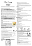
Step 3: Adjust rackmount rails to fit your rack
These versatile Step-Down Transformers can be mounted in a rackmount
or vertical tower orientation. This versatility is especially important to
growing organizations with changing needs that value having the option
to position a Step-Down Transformer on a floor or in a rackmount system.
Please follow the instructions below for the respective mounting methods.
Attach the rackmount rail to your rack with two M5X12L screws and two
plastic washers at the front of the rack. (Located in position 1 & position 6)
Do not tighten the screws. Adjust the rail size on the rail assembly of your
rack. Secure the rail to the rear of the rack with two M5X12L screws and
two plastic washers. Tighten all screws at the front and rear of the rail.
SAFETY PRECAUTIONS
CAUTION! To prevent the risk of fire or electric shock, only use the
supplied hardware to attach the mounting brackets.
RACKMOUNT INSTALLATION
Step 1: Rackmount ears installation
Attach the two rackmount ears to the Step-Down Transformer using the
provided screws M5X8L*8pcs.
Place the Step-Down Transformer on a flat stable surface with the front of
the unit facing toward you. Secure the Step-Down Transformer to your
rack with four M5X12L screws at the front of the rack. The 2U Step-Down
Transformer takes up position 2 through position 5. The 3U Step-Down
Transformer takes up position 2 through position 8.
Step 2: Rackmount rail Installation
The rails adjust to mount in 48-cm (19-inch) panel racks from 52 to
91.5cm (20.5 to 36 inches) deep. Select the proper holes in the rack for
positioning the Step-Down Transformer in the rack. The 2U Step-Down
Transformer takes up position 1 through position 6. The 3U Step-Down
Transformer takes up position 1 through position 9.
CAUTION! The Step-Down Transformer must be installed above the
power module.
2
Copyright © 2014 CyberPower Systems, Inc.
HARDWARE INSTALLATION
VERTICAL/TOWER INSTALLATION
Step 1: Rotate the Multifunction LCD Module
Step 2: Attach the base stands
Unscrew the right panel of the power module. Separate the right panel
from the UPS. Gently lift the LCD module out. Rotate it to the tower
orientation. Reinstall it for a tower configuration.
Secure the tie bracket with the screws (M5X8*4pcs). Tighten the screws
(M5X12*4pcs) of the base stands (rackmount ears) onto the bottom of
the power module and the Battery module.
Step 3: Attach dust covers
Insert dust covers into the rackmount ear screw holes that are not being
used.
SAFETY PRECAUTIONS
CAUTION! Installation environment should be in a temperature and
humidity controlled indoor area free of conductive contaminants. Do not
install this UPS where excessive moisture or heat is present (Please see
specifications for acceptable temperature and humidity range).
CAUTION! Never install a UPS, or associated wiring or equipment,
during a lightning storm.
CAUTION! Do not work alone under hazardous conditions.
CAUTION! In case of the risk of electric shock, do not remove the top
cover.
CAUTION! The battery can energize hazardous live parts inside even
when the AC input power is disconnected.
3
Copyright © 2014 CyberPower Systems, Inc.
HARDWIRING THE INPUT TERMINALS
SAFETY PRECAUTIONS
CAUTION! Input circuit breaker must be “OFF” during the building installation.
CAUTION! Only qualified maintenance personnel should perform this task.
CHECK WIRING
Check wiring dimensions with the following table.
Step-Down and Isolation Transformers with hardwire
Wiring AWG
Wiring mm
OL6KRT2UTFHWIO / OL6KRT2UTFHWIOR
10 AWG
5.5 mm
OL10KRT2UTFHWIO / OL10KRT2UTFHWIOR
6 AWG
14.0 mm
Step 1: Separate the top and bottom covers
Loosen the four screws to separate the top and bottom covers.
Step 2: Fix the bottom cover on the terminal block
Tighten the two screws to fix the bottom cover on the terminal block.
4
Copyright © 2014 CyberPower Systems, Inc.
2
2
2
HARDWIRING THE INPUT/ OUTPUT TERMINALS
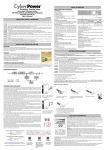
Step 3: Input / Output configuration
Insert the input / output cables through the appropriate cable gland.
Hardwire the input / output terminals as shown in the following terminal block identification and configuration table.
Step 4: Fix the top cover on the bottom cover
Tighten the four screws to fix the top cover on the bottom cover.
5
Copyright © 2014 CyberPower Systems, Inc.
HARDWIRING THE INPUT/ OUTPUT TERMINALS
TERMINAL BLOCK IDENTIFICATION
ISOLATION TERMINAL BLOCK CONFIGURATION
Input Voltage
L1 → L2 = 200Vac
L1 → L2 = 220Vac
L1 → L2 = 230Vac
Input Voltage
AC Output Connection
Output Voltage
L1 → N ← L2
100Vac → 0 ← 100Vac
L1 → L2
200Vac
L1 → N ← L2
110Vac → 0 ← 110Vac
L1 → L2
220Vac
L1 → N ← L2
115Vac → 0 ← 115Vac
L1 → L2
230Vac
AC Output Connection
Output Voltage
L1 → N ← L2
120Vac → 0 ← 120Vac
L1 → L2
240Vac
L1 → L2T
208Vac
AC Output Connection
Output Voltage
L1 → N ← L2
120Vac → 0 ← 120Vac
L1 → L2
240Vac
L1 → L2T
208Vac
L1T → L2 = 208Vac
Input Voltage
L1 → L2 = 240Vac
6
Copyright © 2014 CyberPower Systems, Inc.
HARDWIRING THE INPUT/ OUTPUT TERMINALS
POWER CABLE CONNECTION
OL6000RT3UTF
OL8000RT3UTF / OL10000RT3UTF
OL6000RT3UPDUTF
OL8000RT3UPDUTF / OL10000RT3UPDUTF
7
Copyright © 2014 CyberPower Systems, Inc.
BASIC OPERATION
STEP-DOWN TRANSFORMER FRONT/REAR PANEL DESCRIPTION
1. Input Circuit Breaker
Provides input overload and fault protection.
2. Input Terminal Block / Output Terminal Block
Connect to UPS outlet / output terminal block.
3. Battery Backup & Surge Protected Outlets (120Vac)
Provides battery backup and surge protection. They ensure power is provided to connected equipment over a period of time during a power failure.
4. Output Circuit Breaker (120Vac)
Provides output overload and fault protection.
OL6KRT2UTFHWIO / OL10KRT2UTFHWIO / OL6KRT2UTFHWIOR / OL10KRT2UTFHWIOR
OL6KRT2UTFHWIOR / OL10KRT2UTFHWIOR
OL6KRT2UTFHWIO / OL10KRT2UTFHWIO
8
Copyright © 2014 CyberPower Systems, Inc.
TECHNICAL SPECIFICATIONS
Model
Configuration
Maximum Output Power (VA)*
Maximum Output Power (W)*
Form Factor
Input
Nominal Input Voltage
Input Voltage Range
Input Current Rating
Input Frequency
Output
Nominal Output Voltage
OL6KRT2UTFHWIOR
OL10KRT2UTFHWIOR
6000VA
6000W
OL10KRT2UTFHWIO
10000VA
10000W
Rackmount / Tower
200/208/220/230/240Vac
200-240Vac
30A
50A
50/60Hz
(6) 5-20R
(1) Terminal block
UPS Outlets
OL6KRT2UTFHWIO
Physical
Dimensions
Net Weight
Environment
Operating Temperature
Operating Relative Humidity
Safety
Conformance Approvals
100/110/115/120Vac or 200/208/220/230/240Vac
(6) 5-20R
(1) Terminal block
(1) Terminal block
(1) Terminal block
L x W x H = 23.6 x 17 x 3.46in. (60 x 43.3 x 8.8cm)
95.5lbs(43.4Kg)
119.7lbs(54.4Kg)
32℉ to 104℉ ( 0℃ to 40℃)
0 to 90% Non-Condensing
CE, UL, BSMI
*200V are derated by 20%, 208 V are derated by 10% for OL10KRT2UTFHWIOR / OL10KRT2UTFHWIO
SAFETY PRECAUTIONS
CAUTION! Before connecting to the UPS, check that the input voltage into the UPS is within specifications.
CyberPower Systems Inc.
www.cpsww.com
©
Entire contents copyright 2014 CyberPower Systems Inc., All rights reserved. Reproduction in whole or in part
®
®
without permission is prohibited. PowerPanel Business Edition and PowerPanel Personal Edition are trademarks of
CyberPower Systems Inc
9
Copyright © 2014 CyberPower Systems, Inc.
PRODUCT REGISTRATION
CyberPower requests that you complete and return the Warranty Registration Card enclosed with the Product or register the Product at its website
(www.cpsww.com) to establish that you are the Initial Customer of the Product, and therefore entitled coverage under the Limited Warranty and the Connected
Equipment Guarantee. (Registration is not required for coverage, but note: if you do not register your purchase, you will be required to provide proof of
purchase.)
LIMITED WARRANTY AND CONNECTED EQUIPMENT GUARNTEE
Read the following terms and conditions carefully before using the CyberPower OL6KRT2UTFHWIO / OL6KRT2UTFHWIOR / OL10KRT2UTFHWIO /
OL10KRT2UTFHWIOR. By using the Product you consent to be bound by and become a party to the terms and conditions of this Limited Warranty and
Connected Equipment Guarantee (together referred to as this “Warranty”). If you do not agree to the terms and conditions of this Warranty, you should return
the Product for a full refund prior to using it.
Who is Providing this Warranty?
CyberPower Systems (USA), Inc. (“CyberPower”) provides this Limited Warranty.
What Does This Warranty Cover?
This warranty covers defects in materials and workmanship in the Product under normal use and conditions. It also covers equipment that was connected to
the Product and damaged because of the failure of the Product.
What is the Period of Coverage?
This warranty covers the Product for three years and connected equipment for as long as you own the Product.
Who Is Covered?
This warranty only covers the original purchaser. Coverage ends if you sell or otherwise transfer the Product.
How Do You Get Warranty Service?
1. Before contacting CyberPower, identify Your Product model number, the Purchase Date, and each item of Connected Equipment.
2. Email us at [email protected] or Call us at (877) 297-6937.
3. If your product requires warranty service you must provide a copy of your dated purchase receipt or invoice.
How Do You Open A Connected Equipment Claim?
1. Call us at (877) 297-6937 or write to us at Cyber Power Systems (USA), Inc., 4241 12th Ave. E., STE 400, Shakopee, MN 55379, or send us an e-mail
message at [email protected] for instructions, within 10 days of the occurrence.
2. When you contact CyberPower, identify the Product, the Purchase Date, and the item(s) of Connected Equipment. Have information on all applicable
insurance or other resources of recovery/payment that are available to the Initial Customer and Request a Claim Number.
3. You must provide a dated purchase receipt (or other proof of the original purchase) and provide a description of the damage to your connected equipment.
4. Pack and ship the product to CyberPower and, if requested, the item(s) of Connected Equipment, a repair cost estimate for the damage to the Connected
Equipment, and all claim forms that CyberPower provides to you. Show the Claim Number on the shipping label or include it with the product. You must
prepay all shipping costs, you are responsible for packaging and shipment, and you must pay the cost of the repair estimate.
How Long Do I Have To Make A Claim?
All claims must be made within ten days of the occurrence.
What Will We Do To Correct Problems?
CyberPower will inspect and examine the Product.
If the Product is defective in material or workmanship, CyberPower will repair or replace it at CyberPower's expense, or, if CyberPower is unable to or decides
not to repair or replace the Product (if defective) within a reasonable time, CyberPower will refund to you the full purchase price you paid for the Product
(purchase receipt showing price paid is required).
10
Copyright © 2014 CyberPower Systems, Inc.
LIMITED WARRANTY AND CONNECTED EQUIPMENT GUARNTEE
Who Pays For Shipping?
We pay when we send items to you; you pay when you send items to us.
What Are Some Examples Of What This Warranty Does Not Cover?
1. This Warranty does not cover any software that was damaged or needs to be replaced due to the failure of the Product or any data that is lost as a result of
the failure or the restoration of data or records, or the reinstallation of software.
2. This Warranty does not cover or apply to: misuse, modification, operation or storage outside environmental limits of the Product or the equipment
connected to it, nor for damage while in transit or in storage, nor if there has been improper operation or maintenance, or use with items not designed or
intended for use with the Product, such as laser printers, appliances, aquariums, medical or life support devices, etc.
What Other Limitations Apply?
The sole and exclusive remedies of the Initial Customer are those provided by this Warranty.
1. This Warranty does not apply unless the Product and the equipment that was connected to it were connected to properly wired and grounded outlets
(including compliance with electrical and safety codes of the most current electrical code), without the use of any adapters or other connectors.
2. The Product must have been plugged directly into the power source and the equipment connected to the Product must be directly connected to the Product
and not “daisy-chained” together in serial fashion with any extension cords, another Product or device similar to the Product, surge suppressor, or power tap.
Any such installation voids the Limited Warranty.
3. The Product and equipment connected to it must have been used properly in a suitable and proper environment and in conformance with any license,
instruction manual, or warnings provided with the Product and the equipment connected to it.
4. The Product must have been used at all times within the limitations on the Product’s VA capacity.
The Product was designed to eliminate disrupting and damaging effects of momentary (less than 1ms) voltage spikes or impulses from lightning or other
power transients. If it can be shown that a voltage spike lasting longer than 1ms has occurred, the occurrence will be deemed outside the rated capabilities of
the Product and the Limited Warranty is void. CyberPower Does Not Cover or Undertake Any Liability in Any Event for Any of the Following:
1. Loss of or damage to data, records, or software or the restoration of data or records, or the reinstallation of software.
2. Damage from causes other than AC Power Line Transients, spikes, or surges on properly installed, grounded and code-compliant 120 volt power lines in
the United States and Canada; transients, surges or spikes on standard telephone land lines, PBX telephone equipment lines or Base 10T Ethernet lines,
when properly installed and connected. (This exclusion applies, for example, to fluctuations in data transmission or reception, by CATV or RF transmission or
fluctuations, or by transients in such transmission.)
3. Damage from any circumstance described as excluded above with respect to the Product.
4. Damages from fire, flood, wind, rain, rising water, leakage or breakage of plumbing, abuse, misuse or alteration of either the product or the Connected
Equipment.
5. CyberPower excludes any liability for personal injury under the Limited Warranty and Connected Equipment Guarantee. CyberPower excludes any liability
for direct, indirect, special, incidental or consequential damages, whether for damage to or loss of property [EXCEPT FOR (AND ONLY FOR) the specific
limited agreement of CyberPower to provide certain warranty benefits regarding "Connected Equipment" under this Warranty], loss of profits, business
interruption, or loss of information or data. NOTE: Some States or Provinces do not allow the exclusion or limitation of incidental or consequential damages,
so the above limitation may not apply to you.
6. The Product is not for use in high-risk activities or with aquariums. The Product is not designed or intended for use in hazardous environments requiring
fail-safe performance, or for use in any circumstance in which the failure of the Product could lead directly to death, personal injury, or severe physical or
property damage, or that would affect operation or safety of any medical or life support device (collectively, "High Risk Activities"). CyberPower expressly
disclaims any express or implied warranty of fitness for High Risk Activities or with aquariums. CyberPower does not authorize use of any Product in any High
Risk Activities or with Aquariums. ANY SUCH USE IS IMPROPER AND IS A MISUSE OF THE PRODUCT.
Where Can I Get More Information?
The application of the United Nations Convention of Contracts for the International Sale of Goods is expressly excluded.
CyberPower is the warrantor under this Limited Warranty.
For further information please feel free to contact CyberPower at CyberPower Systems (USA), Inc. 4241 12th Ave E., STE 400, Shakopee, MN 55379; call us
at (877) 297-6937; or send us an e-mail message at [email protected].
11
Copyright © 2014 CyberPower Systems, Inc.
CONFORMANCE APPROVALS
FCC Notice
This device complies with part 15 of the FCC Rules. Operation is subject to the following two conditions: (1) This device may not cause
harmful interference, and (2) this device must accept any interference that may cause undesired operation.
WARNING!! This equipment has been tested and found to comply with the limits for a Class A digital device, pursuant to part 15 of the FCC Rules. These
limits are designed to provide reasonable protection against harmful interference when the equipment is operated in a commercial environment. This
equipment generates, uses, and can radiate radio frequency energy and, if not installed and used in accordance with the instruction manual, may cause
harmful interference to radio communications. Operation of this equipment in a residential area is likely to cause harmful interference in which case the user
will be required to correct the interference at his own expense. Shielded signal cables must be used with this product to ensure compliance with the Class A
FCC limits.
The Class A digital apparatus meets all requirements of the Canadian Interference-Causing Equipment Regulation.
Cet appareil numerique de la class A respecte toutes les exigencies du Reglement sur le materiel brouilleur du Canada.
This document is believed to be accurate, but CyberPower reserves the right to change or correct the contents and does not assume any responsibility for
omissions or errors.
Need Additional Help?
Feel free to contact our Tech Support department with installation, troubleshooting, or general product questions.
CyberPower Technical Support
Phone: 1-877-297-6937
Email: [email protected]
Web: www.CPSww.com
Mail: 4241 12th Avenue E, Suite 400 Shakopee, MN 55379
Hours of Operation:
Monday – Friday, 7:00am – 6:00pm (CST)
Entire contents copyright © 2014 CyberPower Systems, Inc.
All rights reserved. Reproduction in whole or in part without permission is prohibited.
12
Copyright © 2014 CyberPower Systems, Inc.