1
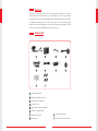
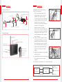
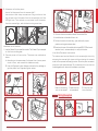
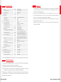
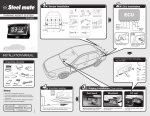
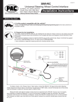
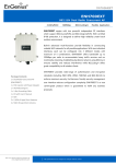
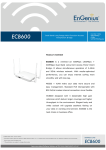
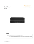
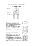
Digital Wireless Backup Camera
System with 3.6" TFT - LCD Monitor
Model: VTX3600
EU Environmental Protection
Waste electrical products should
not be disposed of with household
waste. Please recycle where
facilities exist. Check with your
local authority or retailer for
recycling advice.
Model: VTX3600
Version 1.0
Please read this user manual carefully before using this product.
Failure to understand operation procedures may result in injury.
Welcome
Thank you for choosing our backup camera system. Please
install and use the product in accordance with our operation
instructions. We will provide quality and reliable service for a variety
of vehicles including cars, trucks, and so on. W e implement rigid
quality control and testing to ensure the best performance of the
product as well as satisfactory service for you.
Packing List
10
Transmitter Box
Digital Wireless Monitor
Antenna for Monitor
Suction Cup
Cigarette Lighter Adapter
Power Supply Cable
Camera Screws
Video Out Cable
Grommet
10
In-line Wire Connectors
Installation
Structure
Installation of the wire camera.
(Only for reference) :
Rearview Camera
Power Supply Connection
Pairing Button
Video output
Video input
Transmitter Box
Antenna
Wire Camera
Power input
Power output
Digital Wireless
Antenna
TFT-LCD
Power ON/OFF
Power Indicator
Pairing Indicator
Pairing Button
Video out
Power Supply
Socket
Revolving Button
Brightness
Contrast
1. Drill three holes above the
license plate frame: one for
passing the cable through
the car body; two for installing
camera. Before drilling, check
whether there is any part
behind the hole-drilling position.
If there is, for example,
electronic part or fueling
system part, take all necessary
measures to avoid any possible
damage to these parts. If the
car has existing holes, please
skip this step;
2. After the hole is drilled, insert
the supplied washer, and then
pass the power cable through
the Grommet and into the car.
The Grommet shall be used to
prevent the metal side of the
hole from cutting the power
cable;
3. Adjust the camera to a suitable
angle for view;
4. Install Camera Screws we supplied
to the other holes with the
camera.
5. Connect the camera to the Transmitter Box,
RCA
Connection
Wire
Camera
Red
Transmitter
box
Power
Connection
Black
+12VDC
REV LAMP
Reverse Lamp
Ground
6. A detector to find the power:
how to find the power from the reverse light?
Instructions: black clamp connects to the ground wire. Use
the red pen to find the power from the reverse light until the
LED light is on. Then connect our red power line to the power
from the reverse light, and the black to the ground wire.
1
2
3
6
5
4
A detector
to find
the power
Red wire
2P
Reverse
light
Black wire
Ground
Installation of the monitor:
1. Use the Suction Cup to install the monitor. The Suction Cup is stamped
on the front window glass.
2. Connect power of the monitor. There are two methods as
below:
A: According to the same steps, find power from the car power
circuit in front, and connect the cables correctly.
B: Use the Cigarette Lighter Adapter included in the package to
get the power form cigarette lighter socket
1
3. Connect the camera and wireless Transmitter Box.
4. Install the box on the side of the trunk.
5.Find and connect the reversing light cable with proper
positive and negative electrodes.
6.Stand on the rear of the vehicle with a board(30X100cm)strait
stood on hand, reverses slowly to verify the function.
In-line Wire Connector Instructions
The camera can be wired directly to the reverse light circuit by
stripping the reverse light wires and then twisting the camera
wires to the exposed reverse light wires. Once they are connected,
wrap them with electrical tape. Do not attempt this if you are not
knowledgeable with electrical installation practices.
2
1.Insert the existing
wire to be tapped.
2.Insert the wire
to be attached.
Pairing the system
3
4
3.Crimp tap and
then close lock
The system is originally paired up from the factory setting, in any case
the system loosed pairing, please follow the below instructions to
pair up again.
1 Make sure camera and Transmitter Box are appropriate connected,
and both Transmitter Box and Monitor are powered up.
5, Default Setting:
Press the Brightness and Contrast buttons at the same
time, and the reset is done, both contrast, brightness
and image orientation return to the default setting.
6, Save the settings:
System will automatically save all the user settings.
2 Press and hold the "Pair" button on the monitor for 3 second, the
orange light will start to flash and monitor shows a counting down
number from 30 to 0, you have 30 seconds to press and "Pair"
button on the Transmitter Box to pair up the system.
Testing the System
Normal
Mirror
Mirror Upside
Down
Normal Upside
Down
TRANSMITTER SPECIFICATIONS
3 To use a pen or small tip to press and hold the "pair" button on the
Transmitter Box for 3 seconds when the Monitor is counting down.
The camera image should be showed up on the monitor, which means
the pairing succeed.
4 Video are able to be output from the monitor to bigger display device
such as TV or other screen with a RCA video input.
Specifications
Items
Unit
Specification
Operating Frequency
MHZ
2400-2483.5
Bandwidth
MHZ
4.4(20dB BW)
Transmitting Power
dBm
+14dBm @ 16QAM EVM 5%,
+18dBm @ QPSK EVM 8%
Receiving Sensitivity
dBm
Modulating/Demodulating Method
-72dBm@QAM, -85dBm@QPSK
Proprietary Frequency Hopping
Signaling With Digital Modulation
Safety
32 Bit ID
Antenna Gain
Unobstructed Effective Range
Power Supply
Max Consumption current
Operation Temperature
Storage Temperature
dBi
m
VDC
mA
2(Omni-directional Dipole)
≥50
DC 12V
DC 12V@250
℃/°F
-10~+50°
℃
-20~+60°
Operation Humidity
RH
Dimensions
mm
Weight
1,Image Orientation:
There are four different ways to view the image from the
m o n i t o r, p r e s s t h e I m a g e O r i e n t a t i o n b u t t o n , y o u c a n
change the image in four different way, depends on where
a n d h o w y o u i n s t a l l t h e c a m e r a , m a ke s u r e y o u h a v e t h e
right Image Orientation before it to backup your car.
2, Contrast Adjustment:
Press the Contrast button to adjust the monitor contrast,
there are 7 levels setting changes by each time press the
Contrast button.
3, Brightness Adjustment:
Press the Brightness button to adjust the monitor brightness,
there are 7 levels setting changes by each time press the
Brightness button.
4, ON/OFF:
The Monitor will automatically turn on when the camera
powered up, if the Monitor does not turn on, press the
ON/OFF button one more time.
16QAM,QPSK,BPSK
g
15%~85%
66x35x12
60±5g
* All the specifications are subject to minor change without prior notice.
Cautions
Specifications
Unit
Items
VIDEO
DISPLAY
LCD Screen Type
3.6", TFT LCD
Effective Pixels
Brightness
320 X 240
cd/m2
Contrast
Lens Mount
degree
Frame Rate
fps
Video Resulutions
200
●
350
●
L:60/R:60/U:40/D:60
30
●
VGA
Video Compression
MPEG-4
Video Signal Output
CVBS,1Vp-p@75ohm
Video Output Format
PAL/NTSC
Operating Frequency
MHz
2400-2483.5
Bandwidth
MHz
4.4(20dB BW)
Modulating/Demodulating Method
RF
Specification
●
●
The apparatus shall not be exposed to dripping or splashing
and no objects filled with liquids, such as vases, shall be
placed on the apparatus.
Turn off the Camera/Monitor if the system is not in use.
The Camera/Monitor can only be completely disconnected
from the mains by unplugging the adapter.
Do not cut the DC power cable of the apparatus to fit with
another power source.
Attention should be drawn to the environment aspects of
battery disposal.
16QAM,QPSK,BPSK
Transmitting Power
dBm
Receiving Sensitivity
dBm
+14dBm @ 16QAM EVM 5%,
+18dBm @ QPSK EVM 8%
-72dBm@QAM, -85dBm@QPSK
Proprietary Frequency Hopping
Signaling With Digital Modulation
Safety
32Bit ID
Antenna Gain
Unobstructed Effective Range
dBi
m
GENERAL
Power Supply
Consumption Current
≥50
DC +12/24V
mA
g
Weight
2(Omni-directional Dipole)
250(max)
128±20
Dimensions
mm
Operation Temperature
℃/°
-10~+50
Storage Temperature
℃/°
-20~+60°
Operation Humidity
RH
15%~85%
108x75x38
* All the specifications are subject to minor change without prior notice.
FCC Information
This device complies with part 15 of the FCC Rules. Operation
is subject to the following two conditions:
(1) This device may not cause harmful interference,
(2) This device must accept any interference received, including
interference that may cause undesired operation.
Changes or modifications not expressly approved by the party
responsible for compliance could void the user's authority to
operate the equipment.
BOYO SENSORS
BACK UP SENSOR SYSTEMS