1
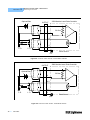
CALIBRATION TEC Calibration Procedures CHAPTER 3 Local Operation ITE Current Calibration The following procedure is for calibrating the ITE constant current source for both polarities of current. This procedure calibrates the zero current set point automatically, then it automatically drives the TE current output to internally set limits of +1 amp. When each of these values is reached and is stable, the user enters the actual value of the current, as measured by an external DMM. The LDC-3900 then automatically calibrates the TEC current source and limits. This procedure is for local (front panel) operation. 1 With the output off, connect a 1, 10 W resistor across the TEC output terminals (on the TE OUTPUT connector, see Figure 2.1) and use a calibrated DMM to measure the voltage across the resistor. Calculate the current in the following steps by using Ohm's Law: I=E/R -where E is the accurately measured voltage across the resistor, and R is the accurately measured load resistance. (A 4-point probe resistance measurement is recommended.) Select the LCM-39425 for calibration by pressing the appropriate (ADJUST) LAS/TEC switch (so that the TEC indicator is orange). If the TEC output is not off, the TEC current calibration mode cannot be entered. 2 Press the (GPIB) LOCAL and (TEC DISPLAY) ITE switches at the same time to place the LCM-39425 in its TEC Current Calibration mode. The OUTPUT must be off to enter the TEC calibration mode. The LDC-3900 will automatically turn the LCM-39425 OUTPUT on during calibration, when it is required. The TEC display will show a value of about zero amps as the LCM-39425 calibrates itself for a zero current level. After about 20 seconds the LDC-3900 will beep and the TEC display will begin to change to show about 1 amp, for calibration. 3 After the value on the TEC display is stable (has not changed by more than one digit for several seconds) the LDC-3900 is ready for the actual I value to be entered. Press and hold in the (PARAMETER) SET switch and turn the ADJUST knob until the TEC display shows the correct value, as calculated from Step 1. 08_13 4 Release the (PARAMETER) SET switch to store the new calibration value into nonvolatile memory on the LCM-39425. The LDC-3900 will then beep to indicate that it is ready for the user to enter the calibration value for its negative polarity output. 5 Repeat Steps 3 and 4 for the negative polarity of the TEC output current. After the value for the negative polarity of the TEC output is entered, the LCM-39425 will automatically calibrate its current limits and set points. After a few seconds, the LDC-3900 will return to its former state (before calibration). The LDC-3900 will beep when it has finished storing all of the new calibration values. LCM-39425 27