1
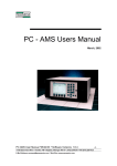
PPM Users Manual Signature Software 01-12-00 PPM User Manual 11/18/02 Software Versions: 0.0.27 Promess Montage- und Prüfsysteme GmbH Berlin 1 Contents 1. Introduction 2 2. Parameters 3 2.1 Overload Limit.............................................................................................4 2.2 Relative Upper Limit ...................................................................................4 2.3 Relative Lower Limit...................................................................................4 2.4 Absolute Upper Limit ..................................................................................5 2.5 Absolute Lower Limit..................................................................................5 2.6 Start of Window...........................................................................................5 2.7 End of Window ............................................................................................5 2.8 Slice Width...................................................................................................5 2.9 Slice Tolerance.............................................................................................6 2.10 Force Limit.................................................................................................6 2.11 Peak Force Monitoring ..............................................................................7 Peak Upper Limit...................................................................................7 Peak Lower Limit ..................................................................................7 2.12 Global Peak Force Monitoring...................................................................7 Global Peak Upper Limit .......................................................................7 Global Peak Lower limit........................................................................7 2.13 Touch Point Limit ......................................................................................8 2.14 Touch Point Tolerance...............................................................................8 2.15 Full Depth Tolerance .................................................................................9 3. Teaching the System 10 3.1 Teaching The Signature Curve ..................................................................11 3.2 Adjusting Parameters .................................................................................12 3.3 Window Limits Screen ..............................................................................13 3.4 Global Limits Screen .................................................................................15 3.5 Zoom Window Screen ...............................................................................16 3.6 Example Teach-In Press Application.........................................................17 4. Automatic Mode 18 4.1 The Fault List Screen .................................................................................19 4.2 Information Screens ...................................................................................20 4.2.1 Manufacturing Summary Screen ................................................20 4.2.2 Part Data Screen..........................................................................21 4.2.3 Taught Data Screen.....................................................................21 4.2.4 Data Lists Screen ........................................................................22 5.0 The Service Menu 24 5.1 Diagnostics.................................................................................................24 5.1.1 Sensor Signals.............................................................................25 5.1.2 Input Check.................................................................................26 PPM User Manual 11/18/02 Software Versions: 0.0.15 Promess Montage- und Prüfsysteme GmbH Berlin 2 5.1.3 Relay Output Check....................................................................27 5.2 Calibration..................................................................................................28 5.2.1 Calibrate Force............................................................................29 5.2.2 Calibrate Position........................................................................31 5.2.3 Reset Force Factor ......................................................................33 5.2.4 Reset Position Factor ..................................................................33 5.2.5 Edit Force Factor.........................................................................34 5.2.6 Edit Position Factor.....................................................................35 5.3 Setup Screen...............................................................................................36 5.3.1 Changing Password.....................................................................37 5.3.2 Changing Date and Time ............................................................38 5.3.3 Serial Baud Rate .........................................................................38 5.3.4 Changing Language ....................................................................39 6. RS232 Serial Communication 40 6.1 Communication Settings............................................................................40 6.2 Signal Description......................................................................................40 6.3 Command Format ......................................................................................41 Command: TPT<CR>.........................................................................42 Command: TPL<CR>.........................................................................42 Command: TPS<CR> .........................................................................42 Command: TPA<CR> ........................................................................42 Command: FDA<CR>........................................................................43 Command: FDT<CR> ........................................................................43 Command: FDL<CR> ........................................................................43 Command: FDS<CR>.........................................................................43 Command: PFW<CR>........................................................................44 Command: PFG<CR>.........................................................................44 Command: CWA<CR>.......................................................................45 Command: CWT<CR> .......................................................................45 Command: CWL<CR> .......................................................................45 Command: CWS<CR> .......................................................................46 PPM User Manual 11/18/02 Software Versions: 0.0.27 Promess Montage- und Prüfsysteme GmbH Berlin 3 1. Introduction The Promess Assembly Monitoring System is designed to monitor, in-process, the quality of a press-fit, staking or crimping operation or any other process requiring signature monitoring. The system consists of a microprocessor based electronic unit which monitors the signals from force and position sensors mounted on the machine. Information obtained from these sensors is used to create a force/position signature curve, which is compared to an "ideal" taught profile. If the force exceeds preset limits (either upper or lower), or if the part is not pressed to the correct depth, a fault is indicated. The assembly profile is monitored within an adjustable window, which allows the user to define the critical portion of the assembly operation for precise in-process quality information. Individual stations can also be linked together to a single monitoring PC using a daisy-chain method. While each station is responsible for monitoring its own operations in real time, the host PC collects all resulting data from each station for viewing, editing and analysis. The data acquisition software is Windowsbased and can be used in a single or multi-station configuration. PPM User Manual 11/18/02 Software Versions: 0.0.15 Promess Montage- und Prüfsysteme GmbH Berlin 2 2. Parameters The Promess Assembly Monitoring System has multiple parameters that can be used during the assembly monitoring process. Note: the Overload limit, Force Limit, Absolute Limits, the Peak limits are disabled as a default setting in the Limit Enable screen. If any of and these limits are to be used, they must be enabled in the Limit Enable screen in the hidden setup menu (see technical manual). Overload Limit Relative Upper Limit Relative Lower Limit Absolute Upper Limit Absolute Upper Limit Start of Window End of Window Slice Width Slice Tolerance Force Limit Peak Upper Limit Peak Lower Limit Global Peak Upper Limit Global Peak Lower Limit Touch Point Limit Full Depth Limit Monitoring Window Force Overload Limit Upper Limit Lower Limit - + Full Depth Tolerance Start of Window Touch Point Tolerance - + End of Window Touch Point Limit PPM User Manual 11/18/02 Software Versions: 0.0.27 Promess Montage- und Prüfsysteme GmbH Berlin 3 Position 2.1 Overload Limit The over load limit is a real time limit and is active when the monitored input is high. When the force exceeds the overload limit, an overload fault output is triggered. Force Overload Limit Position 2.2 Relative Upper Limit The relative upper limit is monitored from the Start of Window to the End of Window. The relative upper limit is calculated by taking the relative upper limit setting and adding it to the taught-in force profile. If the force at any position during the monitoring window exceeds the upper limit, a force fault will occur. 2.3 Relative Lower Limit The relative lower limit is monitored from the Start of Window to the End of Window. The relative lower limit is calculated by taking the relative lower limit and subtracting it from the taught-in force profile. If the force at any time during the monitoring window drops below the lower limit, a force fault will occur. Monitoring Window Relative Upper Limit Relative Lower Limit Position PPM User Manual 11/18/02 Software Versions: 0.0.15 Promess Montage- und Prüfsysteme GmbH Berlin 4 2.4 Absolute Upper Limit The absolute upper limit is monitored from the Start of Window to the End of Window. If the force at any position during the monitoring window exceeds the upper limit, a force fault will occur. 2.5 Absolute Lower Limit The absolute upper limit is monitored from the Start of Window to the End of Window. If the force at any position during the monitoring window falls below the lower limit, a force fault will occur. Monitoring Window Force Absolute Upper Limit Absolute Lower Limit Position 2.6 Start of Window The position where monitoring will start. If the touch point limit is set to 00%, then the start of window is an absolute setting of the position axis. If the touch point is used, the start of window will be relative to the touch point. 2.7 End of Window The position where monitoring will end. If the touch point limit is set to 00%, then the end of window is an absolute setting of the position axis. If the touch point is used, the end of window will be relative to the touch point. 2.8 Slice Width This specifies how many slices the monitoring window will be separated into for analysis. The monitoring window is sliced into position dependent slices, and within each slice, an average force is computed. Each slice has an associated upper and lower limit, which are used when certifying the part. The Number of Slices can only be changed in the Teach mode. PPM User Manual 11/18/02 Software Versions: 0.0.27 Promess Montage- und Prüfsysteme GmbH Berlin 5 2.9 Slice Tolerance This parameter shifts each window increment to the right and left and takes the highest and lowest value to establish the limits. This is used to compensate for variations in position causing the force curve to shift. This parameter is set in the setup menu. Force Monitoring Window Relative Upper Limit Relative Lower Limit Start of Window End of Window Position 2.10 Force Limit The Force limit is a real time limit that can be used to ensure a certain force is reached or to control the ram to press to a force. The monitoring of the force limit is active when the monitored input is high. Force Force Limit Position PPM User Manual 11/18/02 Software Versions: 0.0.15 Promess Montage- und Prüfsysteme GmbH Berlin 6 2.11 Peak Force Monitoring The Peak Force value that is displayed is the highest force the unit recorded with the monitoring window during the process. Peak Upper Limit The Peak Upper limit is a straight line limit. If the peak force measured exceeds the Peak Upper limit then a Peak limit fault will occur at the end of the cycle. Peak Lower Limit The Peak Lower limit is a straight line limit. If the peak force measured is lower then the Peak Lower limit then a Peak limit fault will occur at the end of the cycle. 2.12 Global Peak Force Monitoring The Global Peak Force value is the highest force that the unit recorded that was inside or outside the monitoring limit. Global Peak Upper Limit The Peak Upper limit is a straight line limit. If the peak force measured exceeds the Peak Upper limit then a Peak limit fault will occur at the end of the cycle. Global Peak Lower limit The Peak Lower limit is a straight line limit. If the peak force measured is lower then the Peak Lower limit then a Peak limit fault will occur at the end of the cycle. PPM User Manual 11/18/02 Software Versions: 0.0.27 Promess Montage- und Prüfsysteme GmbH Berlin 7 2.13 Touch Point Limit The initial contact of the parts is recognized by this limit. The start of window and end of window are relative to the touch point. Force Touch Point Limit Monitoring Window Touch Point Tolerance Position 2.14 Touch Point Tolerance Based upon the taught-in touch point position, the user can set a plus/minus tolerance that the initial part contact (Touch Point) must be within. When the Assembly Monitoring System is taught, the system stores the Touch Point Position. The Touch point tolerance set in the parameter screen and the value entered is added and subtracted from the taught Touch Point position to create the tolerance. Example: Taught in Touch Point Position is 13.50mm Touch Point Tolerance is 2.00mm Then the lower limit is 11.50mm and the upper limit is 15.50mm. So if the Touch Point position is less than 11.50mm or greater than 15.50mm then a fault will be sent. Lower Tolerance 00.00 Taught 11.50 13.50 Upper Tolerance 15.50 25.00 Position PPM User Manual 11/18/02 Software Versions: 0.0.15 Promess Montage- und Prüfsysteme GmbH Berlin 8 2.15 Full Depth Tolerance Based upon the taught-in full depth position, the user can set a plus/minus tolerance that the final press position must be within. When the Assembly Monitoring System is taught, the system stores the Full Depth Position (The furthest value that the position transducer traveled). There are two full depth tolerances that can be set in the monitoring system: Full Depth + Tolerance (Full Depth +) Full Depth - Tolerance (Full Depth -) The Full Depth + Tolerance is added to the taught-in full depth value to set the upper limit and the Full Depth - Tolerance is subtracted from the full depth value to set the lower limit. The full depth measurement can be either an absolute measurement or a relative measurement when touch point is used. Note: if the full depth measurement is not going to be used, then set the limits large enough to give no faults. Example Taught Full Depth is 15.20 mm Full Depth + Tolerance +2.00 Full Depth - Tolerance -1.20 So the full depth position must fall within 14.00 to 17.20 mm tolerance otherwise the part will not pass the full depth measurement. Lower Tolerance Taught 00.00 14.00 Upper Tolerance 15.20 17.20 25.00 Position PPM User Manual 11/18/02 Software Versions: 0.0.27 Promess Montage- und Prüfsysteme GmbH Berlin 9 3. Teaching the System The TEACH function is used to teach the Monitoring System the force versus position signature. The unit will switch to the automatic mode once the teach count has been reached. The icon in the upper right corner will display a "T" for teach (versus "A" for automatic). The Overload Limit, Force Limit and the Peak Force Limits are the only limits monitored in the teach mode. If one of these faults occur in the teach mode, the system will stay in the teach mode until a part is taught-in with no faults. To access the Teach Mode from the Main Menu, press the button labeled TEACH. To access the Teach Mode from the Automatic Mode, press the button labeled MAIN to access the Main Menu and then press the button labeled TEACH to access the Teach Mode. The software will ask if you wish to reteach the part. Press Yes to go into Teach or No to exit back to the Main Menu. The system can store 8 different force/position signature curves and parameters, however, when the system is put into Teach, only the part number currently active will be taught. With option memory, up to 64 parts can be taught and stored. The part number is displayed in the Main Menu in the lower right hand corner. The part number is sent using the binary inputs via the interface cable. PROMESS INCORPORATED Promess Panel Meter Version 0.0.9 May 11, 1999 Station: 99 Teach Automatic Program: 1 Service PPM User Manual 11/18/02 Software Versions: 0.0.15 Promess Montage- und Prüfsysteme GmbH Berlin 10 Force Depth 1000 lbs 750 0 lbs 0 mm T Prog: 1 500 250 0 0.00 mm InformaLimits Setup tion 25.00 Main 3.1 Teaching The Signature Curve When in the teach mode, the monitoring system collects and stores both the force and position data during working stroke of the position transducer. In the hidden setup menu under Axis Value Setup, the position range that you want data collected over can be adjusted if necessary. This would only need to be done if you had a long stroke portion transducer but are only using a small amount of travel during the assembly operation. To teach a signature into the system, take parts that are close to the mean and press them together. The two parts that are going to be assembled do not have to be exactly on the mean. The upper and lower limits are separate limits, so if the taught-in signature is above the mean, then the upper limit will be set to a lower value than if a mean part was taught in. The system will indicate when it is in the teach mode by displaying a T in the upper right hand corner of the screen. An A is used to indicate the system is in the automatic mode. After on part is taught, the system will automatically switch to the automatic mode. In teach the only limits that are monitored are the Overload Limit and the Peak Force Limits. In either the teach mode or the automatic mode any of the monitoring parameters can be changed without having to reteach the system. The screen in the teach mode. PPM User Manual 11/18/02 Software Versions: 0.0.27 Promess Montage- und Prüfsysteme GmbH Berlin 11 0 lbs 0 mm Force Depth 1000 lbs 750 Prog: 1 T 500 250 0 0.00 mm InformaLimits Setup tion 25.00 Main 3.2 Adjusting Parameters There are three different screens where various parameter can be adjusted, Window Limits, Global Limits and Zoom Window. Window Limits: In this screen, limits that are only for the Monitoring Window can be adjusted. Global Limits: In this screen, limits that are monitored inside and outside the monitoring window can be adjusted. Zoom Window: This is the screen where the zoom window is set. * Global Limits * * Window Limits * Rel. Upper L. Rel. Lower L. Start Window 10 lbs 10 lbs 0.00mm End Window Slice Width 25.00mm 0.20mm Edit Global Limits Zoom Setup Full Depth + 2.50 mm Full Depth - 2.50 mm Edit Exit Window Limits PPM User Manual 11/18/02 Software Versions: 0.0.15 Promess Montage- und Prüfsysteme GmbH Berlin 12 Zoom Setup Exit * Zoom Window * X Axis 0.00 to 25.00 mm 0 to 100 lbs Window Setup Exit Y Axis Edit Global Setup 3.3 Window Limits Screen In the Program Limits Screen the following parameters can be changed: The Start of Window, End of Window and the Slice Width can be set. The Start of Window and End of Window define where the system monitors the relative upper and relative lower signature limits. The limits can be adjusted without having to reteach the system. The following parameters can be changed. Note: The Peak Upper Limit, Peak Lower Limit, Absolute Upper Limit and Absolute Lower Limit will not appear if disabled in the hidden setup. Relative Upper Limit End of Window Peak Lower Limit Relative Lower Limit Slice Width Absolute Upper Limit Start of Window Peak Upper Limit Absolute Lower Limit * Window Limits * Rel. Upper L. 10 lbs Rel. Lower L. 10 lbs Start Window 0.00mm End Window 25.00mm Slice Width Edit 0.20mm Global Limits Zoom Setup Exit PPM User Manual 11/18/02 Software Versions: 0.0.27 Promess Montage- und Prüfsysteme GmbH Berlin 13 To change a parameter setting, press the Edit button to access the editing mode. * Window Limits * 10 lbs 10 lbs Rel. Upper L. Rel. Lower L. Abs. Upper L. Abs. Lower L. Peak Upper L. Peak Lower L. Start Window End Window Slice Width Edit Button Function ↑↓ Moves the edit box up or down. Clear Clears the current setting. Exit Returns to the previous screen. 0.00mm 25.00mm 0.20mm Global Limits Zoom Setup Exit Changing a Parameter Move the edit box up or down to the parameter to be changed. Press the Clear button and type in the parameter setting. Pressing the Enter button or the Exit button will save the value. Press Exit to exit out of the edit mode and then press Exit to exit back to the graph screen. When you scroll down to Slice Width, the functions of the buttons change to up arrow, +, - and Exit, see screen below. Press Exit to exit out of the edit mode and the press Exit to exit back to the graph screen. * Window Limits * Start Window 5.00 mm End Window Slice Width 20.00 mm 0.60 mm + - Button Function ↑ Moves the edit box up. + Increments the slice width. width. Decrements the slice Exit Returns the software to previous screen. Exit PPM User Manual 11/18/02 Software Versions: 0.0.15 Promess Montage- und Prüfsysteme GmbH Berlin 14 3.4 Global Limits Screen In the Monitoring Window screen, the following parameters can be changed. Overload limit, full depth tolerance, Global peak force limits and the force limit. Note: The Overload limit , Global peak force limits, force limit, and the touch point will not appear if disabled in the hidden setup screen. * Global Limits * Overload L. Full Depth + 100 lbs 2.50 mm Full Depth - 2.50 mm G. Peak U. L. 0 lbs. G. Peak L. L. 0 lbs. Force Limit Touch Point + 0 lbs. 2.50 mm Touch Point Window Edit Limits 2.50 mm Zoom Setup Exit To change a parameter, press the Edit button to access the edition mode. * Global Limits * Overload L. 100 lbs Full Depth + 2.50 mm Full Depth - 2.50 mm Button Function ↑↓ or Moves the edit box up down. G. Peak U. L. 0 lbs. Clear setting. Clears the current G. Peak L. L. 0 lbs. Force Limit 0 lbs. Exit Returns to the previous screen. Touch Point + 2.50 mm Touch Point - 2.50 mm Clear Exit Changing a Parameter Move the edit box up or down to the parameter to be changed. Press the Clear button and type in the parameter setting. Press the Enter button or the Exit button will save the value. Press Exit to exit out of the edit mode and then press Exit to exit back to the graph screen. PPM User Manual 11/18/02 Software Versions: 0.0.27 Promess Montage- und Prüfsysteme GmbH Berlin 15 3.5 Zoom Window Screen In the Zoom Window, the force and position settings for the zooming function can be set. When in the graph screen, pressing the +/- button will toggle the screen from the full graph to the zoom window. * Zoom Window * X Axis 0.00 to 25.00 mm 0 to 100 lbs Window Setup Exit Y Axis Edit Global Setup The following screen appears when entering the Zoom Setup. * Zoom Window * X Axis 0.00 to Button Function ↑↓ Moves the edit box up or down. Clear Clears the current setting. Exit Returns to the previous screen. 25.00 mm Y Axis 0 to 100 lbs Clear Exit Changing a Parameter To change a parameter, move the edit box using the up and down arrow keys. Press the Clear button and then type in the new value and press Enter or Exit to accept the value. To exit out of the Zoom Window screen press the Exit button. PPM User Manual 11/18/02 Software Versions: 0.0.15 Promess Montage- und Prüfsysteme GmbH Berlin 16 3.6 Example Teach-In Press Application Application: pressing a bearing into a housing to a shoulder. The bearing height is 10mm and the housing depth is 10mm. The position transducer has a 25mm stroke length and touch point is not going to be used. First put the Assembly Monitoring System into the Teach Mode and set the Start of Window to 00.00 and the End of Window to 25.00 (full range) in the parameter screen, the other parameters can be left at the default values. Run a cycle, teaching in the force/position curve and the full depth position. Note the full depth value show in the upper left hand corner of the screen and ignore the force position curve. For our example, the full depth value is 20.50. To set up the monitoring window to only look at the critical part of the press-fit, subtract 1mm from the full depth and use this as the End of Window value (19.50). Then subtract 8mm from the full depth value and use this as the Start of Window value (12.50). The critical part of the press-fit is now defined and the force/position curve will be shown on the screen. If necessary, adjust the full depth tolerance. Note: this is just an example and each press-fit application will have a different set of parameters. If you have any questions about setting the window, call Promess at 810-229-9334 for assistance. Ram 10 Bearing Housing 10 Monitoring Window Monitoring Window Force Force Position Position PPM User Manual 11/18/02 Software Versions: 0.0.27 Promess Montage- und Prüfsysteme GmbH Berlin 17 4. Automatic Mode In the Automatic Mode, the monitoring of the press fit operation occurs. The upper and lower limits, the full depth position, the touch point position are monitored in the automatic mode (the Overload limit, the Force limit and the Peak Force limits are also monitored if enabled in the hidden setup menu. The force/position curve is displayed on the LCD screen and is updated after each cycle. The lighter lines are the upper and lower limits and the dark solid line is the actual press force curve. An "A" is displayed in the upper right hand corner to indicate the system is in the Automatic mode. The Full depth position is also displayed in the upper left hand corner of the screen. Using the menu buttons, there are four options in the automatic mode Force Depth 1000 lbs 750 980 lbs 21.45 mm PASS Prog: 1 A 500 250 0 0.00 mm InformaLimits Setup tion 25.00 Main Button Function Limits Setup Brings up the Window limits screen where the parameters can be changed or the Global Limits or the Zoom Setup can also be accessed. Information Brings up the information screens. Main Returns the software to the Main Menu. PPM User Manual 11/18/02 Software Versions: 0.0.15 Promess Montage- und Prüfsysteme GmbH Berlin 18 4.1 The Fault List Screen The Fault List screen lists any faults that occur during the last cycle. This screen is updated after each cycle and the errors displayed are for the last part ran. To access the Fault List screen, press the button labeled Information. To exit back to the graph screen, press the button labeled EXIT. The system still monitors when in the Fault List screen. * Fault List * No Faults Man. Sum. Part Data Data Lists Exit Note: If the force limit is enabled, then the following message will be displayed if the force limit is not reached, Force Limit Not Reached. This does not trigger the Fail output. PPM User Manual 11/18/02 Software Versions: 0.0.27 Promess Montage- und Prüfsysteme GmbH Berlin 19 4.2 Information Screens In the Information Screens, the faults and part data can be viewed. The Fault Lists screen will be displayed. * Fault List * No Faults Man. Sum. Part Data Data Lists Exit 4.2.1 Manufacturing Summary Screen Pressing the Man. Sum. Button will access the Manufacturing Summary Screen. The Manufacturing Summary screen displays the Total number of parts, Good Parts, Bad Parts, Relative Upper limit faults, Relative Lower limit faults and the Full Depth faults. * Manufacturing Summary * Total Parts: Good Parts: Bad Parts: 0 0 0 Rel. Upper L. : Rel. Lower L. : Full Depth + : 0 0 0 Full Depth - : 0 Fault List Reset Counts Exit Button Function Fault List Returns software to Fault List screen ↓ Moves the edit box down. Reset Counts Clears the current setting. Exit previous Returns to the screen. If the Touch point, the Overload limit, the Force limit Absolute or the Peak force limits are enabled in the hidden setup screen, then they will appear in the Manufacturing summary screen. There is a separate manufacturing screen for every part number. PPM User Manual 11/18/02 Software Versions: 0.0.15 Promess Montage- und Prüfsysteme GmbH Berlin 20 4.2.2 Part Data Screen Pressing the Part Data button will show the data for the last part ran. * Part Data * Touch Point 13.14 mm Full Depth 19.30 mm G. Peak Force 9 lbs. W. Peak Force 9 lbs. W. Peak Slice W. Last Slice 9 lbs. 9 lbs. Fault List Taught Data Data Lists Exit 4.2.3 Taught Data Screen Pressing the Taught Data button will show the data for the taught in part. * Taught Data * Touch Point 13.14 mm Full Depth 19.30 mm G. Peak Force 35 lbs W. Peak Force 35 lbs W. Peak Slice W. Last Slice 35 lbs 35 lbs Fault List Part Data Data Lists Exit PPM User Manual 11/18/02 Software Versions: 0.0.27 Promess Montage- und Prüfsysteme GmbH Berlin 21 4.2.4 Data Lists Screen Pressing the Data Lists button will show the Data for the last eight (8) parts. The most recent part will be at the top of the list. * W. Peak Force List * Prog. Peak Force 1 1 1 1 1 1 1 1 Full Depth Status 35 lbs 34 lbs 37 lbs 35 lbs 35 lbs 34 lbs 35 lbs 38 lbs W. Last Slice PASS PASS FAIL PASS PASS PASS PASS FAIL Exit The following screen appears when pushing the Full Depth button. * Full Depth List * Prog. Full Depth 1 1 1 1 1 1 1 1 Full Depth Status 19.64 mm 19.64 mm 19.64 mm 18.02 mm 19.64 mm 19.64 mm 19.64 mm 19.64 mm W. Last Slice PASS PASS PASS FAIL PASS PASS PASS PASS Exit PPM User Manual 11/18/02 Software Versions: 0.0.15 Promess Montage- und Prüfsysteme GmbH Berlin 22 The following screen appears when pushing the W Last Slice button. * W. Last Slice List * Prog. Last Slice 1 1 1 1 1 1 1 1 W. Peak Force Status 35 lbs 34 lbs 34 lbs 34 lbs 37 lbs 34 lbs 34 lbs 34 lbs Full Depth PASS PASS PASS PASS FAIL PASS PASS PASS Exit To exit out of the Data Lists press Exit button. PPM User Manual 11/18/02 Software Versions: 0.0.27 Promess Montage- und Prüfsysteme GmbH Berlin 23 5.0 The Service Menu From the Control Menu the Diagnostics, Setup, Calibration or Main Menu can be accessed. Button Function DIAGNOSTICS Selects the Diagnostics Menu. Service Menu Diagnostics Calibrate Setup Main CALIBRATE Calibrate Selects the Menu. SETUP Selects the Setup Menu. MAIN software to Menu. Returns the the Main 5.1 Diagnostics From the Diagnostics Menu, the Analog Check, Input Check or the Output Check can be selected. Sensor Signal: Displays the force and position in real time. Inputs: Displays the current states of the inputs. Outputs: Displays the current states of the outputs. * Diagnostics Menu * Sensor Signals Inputs Outputs Analog Button Function ↑↓ Moves pointer to desired option. SEL arrow Selects the option the is pointing to. Quadrature Input Serial Port Memory Check Arcnet Check EXIT the Returns the software to Service Menu. Select Exit PPM User Manual 11/18/02 Software Versions: 0.0.15 Promess Montage- und Prüfsysteme GmbH Berlin 24 5.1.1 Sensor Signals The Real Time screen will display the force and position values numerically and in a bar display. This screen can be used when calibrating the system or to verify that the force and position transducers are working properly. * Sensor Signals * (Tare) Force 0 lbs Position 0.00 mm Zero Tare/ Absol. Exit Button Function T/A Toggles between the Tare and Absolute modes. Tare mode uses the current offset values as the zero value when the ZERO button is pressed. The Absolute displays the actual analog values from the transducers. A "T" or an "A" will be displayed in the upper right hand corner of the screen. ZERO Pressing the ZERO button when the system is in the Absolute mode will tare (zero) only the force transducer. When the system is in the Tare mode and the ZERO button is pushed, then the current offset values for both the force and position transducers become the zero points and the readings displayed are relative to the values when the zero button was pushed. MAIN Returns the software to the DIAGNOSTICS MENU. Note: When a Strain Gauge transducer is selected in the Hidden Setup Menu, then the CAL button will be displayed on the screen. When the CAL button is pushed, a signal will be sent to the preamplifier to activate the CAL Resistor. PPM User Manual 11/18/02 Software Versions: 0.0.27 Promess Montage- und Prüfsysteme GmbH Berlin 25 5.1.2 Input Check The Input Check is used to view the current states of the 8 digital inputs: 0 = OFF, 1 = ON. The Input Check can be used to verify that the Monitoring System is receiving the outputs from the PLC or output device. Pressing the MENU button returns the software to the Diagnostics Menu. * Inputs * Inputs: 1 2 3 4 5 6 7 8 0 0 0 0 0 0 0 0 Exit 1 = Monitored Input 2 = Reset fault Input 3 = Binary 1 Input 4 = Binary 2 Input 5 = Binary 4 Input 6 = Binary 8 Input 7 = Not Used 8 = Lockout Input PPM User Manual 11/18/02 Software Versions: 0.0.15 Promess Montage- und Prüfsysteme GmbH Berlin 26 5.1.3 Relay Output Check The Relay Output Check is used to view the current states of the outputs. The screen also permits the toggling of the outputs to verify that the PLC or other device is recognizing the outputs. The outputs will be reset to their original states when exiting the output check. Pressing the MENU button will return the software to the Service screen. The default settings for the relay outputs are listed below. If the assignment of the relay outputs has been changed, consult the system drawings for the correct output description. R1 = Pass (N.O.) R2 = Failed (N.C.) R3 = Overload (N.C.) R4 = Relative Upper Limit Fault (N.C.) R5 = Relative Lower Limit Fault (N.C.) R6 = Full Depth Fault (N.C.) R7 = Ready (N.O.) R8 = Piezo Sensor Reset: FACTORY SETTING DO NOT CHANGE !! The signals that are assigned to each relay output can be changed. See Edit Relay (see technical manual) in the Hidden Setup Menu. * Relay Outputs * Relay: 1 2 3 4 5 6 7 8 1 1 1 1 1 1 1 1 Toggle Button Functions ← on → Positions the "cursor box" the desired relay output. Toggle relay. Toggles the state of the MENU the Returns the software to Diagnostics Menu. Exit PPM User Manual 11/18/02 Software Versions: 0.0.27 Promess Montage- und Prüfsysteme GmbH Berlin 27 5.2 Calibration In calibration, the force transducer can be calibrated using a master load cell and meter. The position transducer can be calibrated using a gauge block. The force and position factors can also be reset and adjusted in the calibration screen. To enter the calibration screen, go to the Service screen and press the Calibration button. The unit will then prompt you to enter the password. Enter the password using the numeric keypad. The default password is 123. To change the password, go to the setup menu. * Password Protect * Enter Password: 123 Then Press "Enter". Clear Exit Once the password is entered correctly and the ENTER key is pressed, the following screen will appear. * Calibration * Calibrate Force Calibrate Position Reset Force Factor Reset Position Factor Edit Force Factor Edit Position Factor Select Calibrate Force: Calibrate Position: Reset Force Factor: Reset Position Factor: Edit Force Factor: Edit Position Factor: Exit Allows the force transducer to be calibrated to a known load. Allows the position transducer to be calibrated to a known gauge block value. Resets the software force factor back to the default. Resets the software position factor back to the default. Allows the software force factor to be adjusted thru the faceplate. Allows the software position factor to be adjusted thru the faceplate. PPM User Manual 11/18/02 Software Versions: 0.0.15 Promess Montage- und Prüfsysteme GmbH Berlin 28 5.2.1 Calibrate Force Using the Calibrate Force function, the force transducer can be calibrated to a known load. This load can be a master load cell and meter. To Calibrate with a known load, complete the following steps. When Calibrate Force is selected the following screen appears. Make sure no load is being applied to the load cell (ram) and press the Zero button. Remove all load then press "Zero". Zero Cancel Next apply the known load and enter the load value applied. Then press the Calibrate button to calibrate to the load. Apply load and enter load applied: Calibration complete. Remove all load 100.00 and then press "Enter" lbs. to continue. Then press "Calibrate" to calibrate the load. Calibrate Clear Exit PPM User Manual 11/18/02 Software Versions: 0.0.27 Promess Montage- und Prüfsysteme GmbH Berlin 29 The analog display will be shown with the force factor calculated. * Edit Force Factor * (Tare) Force 0 lbs Factor: 0.003391 lbs/ADC Press "ENTER" to edit. Zero Tare/ Absol. Exit If no load is detected during this step, a fault will be given. WARNING !!! Calibration Failed. No load was applied. Ok PPM User Manual 11/18/02 Software Versions: 0.0.15 Promess Montage- und Prüfsysteme GmbH Berlin 30 5.2.2 Calibrate Position Using the Calibrate Position function the position transducer can be calibrated to a known position value using a gauge block. To calibrate with a gauge block, complete the following steps. Note: If a digital position transducer is being used, there is not need to use the Calibrate position function. When Calibrate Position is selected the following screen appears. Make sure the position transducer is zeroed with gauge block installed, and then press the Zero button. Move to zero position then press "Zero". Zero Cancel Next insert the gauge block, enter the gauge block value and then press the Calibrate button. After the unit has finished the calibration, a message will appear and tell you to remove the gauge block and press the Enter key. Insert gauge block and enter length of gauge Calibration complete. Remove gauge block block: and then press "Enter" 25.00 mm to continue. Then press "Calibrate" to calibrate to position. Calibrate Clear Exit PPM User Manual 11/18/02 Software Versions: 0.0.27 Promess Montage- und Prüfsysteme GmbH Berlin 31 The analog display will be shown with the position factor calculated. * Edit Position Factor * (Tare) Force 0 mm Factor: 0.003391 mm/ADC Press "ENTER" to edit. Zero Tare/ Absol. Exit If the position transducer is not moved, then a fault message will be displayed. WARNING !!! Calibration Failed. No gauge block inserted. Ok PPM User Manual 11/18/02 Software Versions: 0.0.15 Promess Montage- und Prüfsysteme GmbH Berlin 32 5.2.3 Reset Force Factor The Reset Force Factor is used to reset the force factor back to the default setting. * Reset Force Factor * Reset force factor to full range ? Yes No 5.2.4 Reset Position Factor The Reset Position Factor is used to reset the position factor back to the default setting. * Reset Position Factor * Reset position factor to full range ? Yes No PPM User Manual 11/18/02 Software Versions: 0.0.27 Promess Montage- und Prüfsysteme GmbH Berlin 33 5.2.5 Edit Force Factor In the Edit Force Factor screen the Force Factor can be changed manually. The following screen will be displayed. * Edit Force Factor * (Tare) Force 0 lbs Factor: 0.003391 lbs/ADC Press "ENTER" to edit. Zero Tare/ Absol. Exit Editing the Force Factor. Press the Enter button to edit the force factor. The following screen will appear. Use the numeric keypad to edit the value. * Edit Force Factor * (Tare) Force 0 lbs Factor: 0.003391 lbs/ADC Press "ENTER" to edit. Clear Exit PPM User Manual 11/18/02 Software Versions: 0.0.15 Promess Montage- und Prüfsysteme GmbH Berlin 34 5.2.6 Edit Position Factor In the Edit Position Factor screen the force factor can be changed manually. The following screen will be displayed. * Edit Position Factor * (Tare) Force 0 mm Factor: 0.003391 mm/ADC Press "ENTER" to edit. Zero Tare/ Absol. Exit Editing the Position Factor. Press the Enter button to edit the position factor. The following screen will appear. Use the numeric key pad to edit the value. * Edit Position Factor * (Tare) Force 0 mm Factor: 0.003391 mm/ADC Press "ENTER" to edit. Clear Exit PPM User Manual 11/18/02 Software Versions: 0.0.27 Promess Montage- und Prüfsysteme GmbH Berlin 35 5.3 Setup Screen In the Setup Screen, the Password, Date and time and Language can be changed. * Setup Menu * Change Password Date and Time Button Function ↑↓ Moves pointer to desired option. SELECT Selects the option the arrow is pointing to. Serial Baud Rate Language EXIT Select Returns the software to the Service Menu. Exit PPM User Manual 11/18/02 Software Versions: 0.0.15 Promess Montage- und Prüfsysteme GmbH Berlin 36 5.3.1 Changing Password In the Change Password screen, the password can be changed from the default setting. * Password Protect * Enter Password: 123 Then Press "Enter". Clear Exit The system will then prompt you to enter the new password. * New Password * Enter New Password: 123 Then Press "Enter". Clear Exit Type in the new 3 digit password and press ENTER. A message will be displayed Password Changed. Press Ok to exit. PPM User Manual 11/18/02 Software Versions: 0.0.27 Promess Montage- und Prüfsysteme GmbH Berlin 37 5.3.2 Changing Date and Time In the Date and Time Screen, the date and time that is on the RAM chip can be changed. Press the Edit button to access the edit screen. * Date and Time * Button Function ↑↓ Moves pointer to desired option. Clear number. Clears the selected Exit Returns the software to the Service Menu. 11 / 18 / 19 99 18 : 38 : 1 Clear Exit Move the edit box to the value to be changed and press the Clear button to clear the value. Next enter the new value. Press Exit to exit the edit screen and press Exit a second time to go back to the Diagnostics Screen. Note: To change the year from 2000 back to 1900’s, enter in 99 in the last two digits for the year. 5.3.3 Serial Baud Rate The Serial Baud Rate screen lets you change the Baud Rate for serial communication. * Serial Baud Rate * Baud Rate: 9600 Next Button Functions ← → Changes the setting inside the edit box. Next Not Used. Exit Returns the software to the Setup Menu. Exit PPM User Manual 11/18/02 Software Versions: 0.0.15 Promess Montage- und Prüfsysteme GmbH Berlin 38 5.3.4 Changing Language In the Language Screen, the Language for the text can be set for English or German. * Language * Language: English Next Button Functions ← → Toggles the language from English to German. Toggle relay. Toggles the state of the Menu Returns the software to the Setup Menu. Exit PPM User Manual 11/18/02 Software Versions: 0.0.27 Promess Montage- und Prüfsysteme GmbH Berlin 39 6. RS232 Serial Communication Using the RS232 port, various data from the process can be obtained from the monitoring system in an ASCII format. The data includes the force and position curve data (actual and taught), the peak force inside and outside the monitoring window, the full depth measurements and the touch point data. 6.1 Communication Settings Baud Rate: Data Bits: Stop Bits: Parity: 9600, 19200 or 38,400 8 1 None 6.2 Signal Description TxD: RxD: Transmit signal – Data output Receive signal – Data input External Connector: 9 pin dSub connector 1 1 2 2 PPM 3 Promess 4 Meter 5 3 4 5 PPM User Manual 11/18/02 Software Versions: 0.0.15 Promess Montage- und Prüfsysteme GmbH Berlin 40 Machine Control 6.3 Command Format The Monitoring System looks for a string of three consecutive characters followed by a carriage return. The three characters must be capitalized, otherwise they are ignored. The request for information must be when the Monitored input is low. Every command must be terminated by a carriage return <CR>. <CR> ASCII<#013> Line Feed <LF> after a carriage return <CR> will be ignored. Command Description Availability PSO PSW TPA TPT TPL TPS FDA FDT FDL FDS PFW PFG CWA CWT CWL CWS VAC Part summary with out slices Part summary with slices Touch point actual Touch point taught Touch point limits Touch point summary Full depth actual Full depth taught Full depth limits Full depth summary Peak force window Peak force global Curve window actual Curve window taught Curve window limits Curve summary Value at cursor Later Later Later PPM User Manual 11/18/02 Software Versions: 0.0.27 Promess Montage- und Prüfsysteme GmbH Berlin 41 Command: TPT<CR> Description: Touch Point Taught Value – the taught in touch point location is sent followed by a carriage return. Data Format: Example: touch point taught value<CR> 8.23<CR> Command: TPL<CR> Description: Touch Point Limits – The lower and upper touch point limits are sent out followed by a carriage return. Data Format: touch point lower limit x-axis value, touch point upper limit x-axis value<CR> Example: 8.03,8.43<CR> Command: TPS<CR> Description: Touch Point Summary – The touch point actual value is sent out followed by the lower and upper touch point limits and a carriage return. Data Format: touch point actual value, lower touch point limit, upper touch point limit<CR> Example: 8.23,8.03,8.43<CR> Command: TPA<CR> Description: Touch Point Actual – The touch point location is sent followed by a carriage return. Data Format: Example: touch point x-axis value<CR> 8.23<CR> PPM User Manual 11/18/02 Software Versions: 0.0.15 Promess Montage- und Prüfsysteme GmbH Berlin 42 Command: FDA<CR> Description: Full Depth Actual – The full depth location is sent followed by a carriage return. Data Format: Example: full depth location<CR> 23.74<CR> Command: FDT<CR> Description: Full Depth Taught Value – The taught in full depth location is sent followed by a carriage return. Data Format: Example: full depth taught value<CR> 23.69<CR> Command: FDL<CR> Description: Full Depth Limits – The lower and upper full depth limits are sent out followed by a carriage return. Data Format: full depth lower limit x-axis value, full depth upper limit x-axis value<CR> Example: 23.19,24.19<CR> Command: FDS<CR> Description: Full Depth Summary – The full depth actual value is sent out followed by the lower and upper full depth limits and a carriage return. Data Format: full depth actual value, lower full depth limit, upper touch point limit<CR> Example: 23.74,23.19,24.19<CR> PPM User Manual 11/18/02 Software Versions: 0.0.27 Promess Montage- und Prüfsysteme GmbH Berlin 43 Command: PFW<CR> Description: Peak Force Window – The peak force value within the monitoring window is sent followed by a carriage return. Data Format: Example; peak force window value<CR> 2343<CR> Command: PFG<CR> Description: Peak Force Global – The global peak force value is sent followed by a carriage return. Data Format: Example: peak force global value<CR> 2580<CR> PPM User Manual 11/18/02 Software Versions: 0.0.15 Promess Montage- und Prüfsysteme GmbH Berlin 44 Command: CWA<CR> Description: Curve Window Actual – The actual curve within the monitoring window is sent by sending the x-axis and y-axis values in pairs until all values have been sent followed by a carriage return. Data Format: x-axis 1,y-axis 1,x-axis 2,y-axis 2,x-axis 3,y-axis 3, …x-axis n, y-axis n<CR> Example: 11.00,23,11.10,48,11.20,113, …23.00,1678<CR> Command: CWT<CR> Description: Curve Window Taught – The taught curve within the monitoring window is sent by sending the y-axis and x-axis values in pairs until all values have been sent, followed by a carriage return. Data Format: x-axis 1,y-axis 1,x-axis 2,y-axis 2,x-axis 3,y-axis 3, … x-axis n, y-axis n<CR> Example: 11.00,23,11.10,48,11.20,113,…23.00,1678<CR> Command: CWL<CR> Description: Curve Window Limits - The relative lower and upper limits within the monitoring window are sent out by sending the x-axis value followed by the lower limit y-axis value followed by the upper limit y-axis value in triads until all values have been sent, followed by a carriage return. Data Format: x-axis 1,lower limit y-axis 1,upper limit y-axis 1, x-axis 2,lower limit y-axis 2,upper limit y-axis 2, … x-axis n, lower limit y-axis n, upper limit y-axis n<CR> Example: 11.00,0,123,11.10,0,148,…23.00,1578,1778<CR> PPM User Manual 11/18/02 Software Versions: 0.0.27 Promess Montage- und Prüfsysteme GmbH Berlin 45 Command: CWS<CR> Description: Curve Window Summary – The actual curve within the monitoring window is sent out along with the relative lower and upper limits. Data Format: x-axis 1,actual value y-axis 1,lower limit y-axis 1,upper limit y-axis 1,x-axis 2,actual value y-axis 2,lower limit y-axis 2,upper limit y-axis 2, … x-axis n, actual value y-axis n, lower limit y-axis n, upper limit y-axis n<CR> Example: 11.00,23,0,123,11.10,48,0,148,…23.00,1678,1578,1778<CR> PPM User Manual 11/18/02 Software Versions: 0.0.15 Promess Montage- und Prüfsysteme GmbH Berlin 46