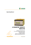
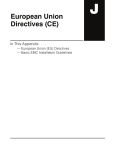
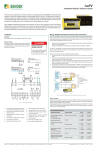
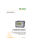
1
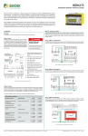
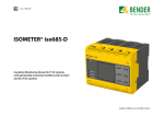
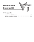
IRDH375
Installation Bulletin / Reference Guide
TM
This document is intended as a reference guide for installing and using a BENDER IRDH375 ground
fault detector. This document includes installation, setup, and usage instructions. For complete details, including installation, setup, settings, and troubleshooting, refer to the IRDH375 user manual,
document number TGH1352en. This document is intended as a supplement and not a replacement to
the complete user manual.
Only qualified maintenance personnel shall operate or service this equipment. These instructions
should not be viewed as sufficient for those who are not otherwise qualified to operate or service this
equipment. This document is intended to provide accurate information only. No responsibility is assumed by BENDER for any consequences arising from use of this document.
Installation
Wiring - Voltage Couplers
Mounting
The IRDH375 is a panel-mounted device. When mounting, use a cutout of 5.4” x 2.6” (138 mm x
66 mm). See reverse side for dimensions.
System voltages greater than 793 VAC / 650 VDC require an additional voltage coupler, installed inline between the IRDH375 and the system. Figures 2 through 4 show wiring schematics for the various available voltage couplers. Locate the wiring diagram utilizing the correct
voltage coupler.
Wiring
See figure 1 for basic wiring schematic. The IRDH375
uses plug-in terminals located on the back of the device.
Line connections (L1 and L2) may use the schematic below for systems below 793 VAC or 650 VDC. For higher
voltages, a voltage coupler is required. See section “Wiring - Voltage Couplers” on additional requirements for
wiring into system connection terminals. Use minimum
AWG 24, maximum AWG 12 wire. For more information,
refer to the IRDH375 user manual.
3Ø AC System
! DANGER
HAZARD OF ELECTRIC SHOCK,
EXPLOSION, OR ARC FLASH
Wiring - IRDH375 and AGH150W-4
The AGH150W-4 is used on DC systems up to 1600 V. Use figure 2 below for wiring. Ensure that
the menu option ISO ADVANCED > AGH is set to “150.” See reverse side for more information.
• Disconnect all power before servicing.
• Observe all local, state, and national
codes, standards, and regulations.
1Ø AC System
Un
Un
3
DC System
2
Un
4
1
11
12
13
Figure 2 - IRDH375 system wiring diagram when using AGH150W-4
9
10
Wiring - IRDH375 and AGH204S-4
The AGH150W-4 is used on AC systems up 1650 V. Use figure 3 below for wiring. Ensure that
the menu option ISO ADVANCED > AGH is set to “204.” See reverse side for more information.
5
7
6
8
Figure 1 - IRDH375 wiring diagram with no voltage coupler
9.
Analog outputs: 0... 400 μA on standard
version, 0/4... 20 mA on “B” version
1.
External supply voltage w/ fusing
2.
Connection, 3Ø AC system
3.
Connection, 1Ø AC system
10. RS-485 interface
4.
Conn. DC system
11. Alarm relay K1: SPDT contact
5.
Equipment ground connection
12. Alarm relay K2: SPDT contact
6.
External TEST terminal, N/O contact
13. Alarm relay K3: SPDT contact
7.
External RESET terminal, N/O contact
8.
STANDBY terminals: Closing F1/F2 will
stop measurements
Wiring - Contacts
Using a normally closed or normally open contact utilizes two factors: wiring out of the proper
terminal, and setting the respective contact to normally energized or deenergized operation.
Refer to the chart below for relay conditions. Changing the energized state of the contact is
done via the ISO SETUP > K1 and ISO SETUP > K2 options found in the main menu.
The factory default for relays K1 and K2 is normally deenergized operation.
Figure 3 - IRDH375 system wiring diagram when using AGH204S-4
Wiring - IRDH375 and AGH520S
The AGH520S is used on AC systems up to 7200 V. Use figure 4 below for wiring. For systems
without neutral, connect to L1. Otherwise, connect to the neutral. Ensure that the menu option ISO ADVANCED > AGH is set to “520S.” See reverse side for more information.
Device Relay Conditions
Relay Operation Setting
Device Alarm State
K1 STATE
K2 STATE
Normally deenergized mode (N/D)
Non-failsafe mode
“N/O” in device settings menu
Power ON, normal state (no alarms)
11-12 CLOSED
11-14 OPEN
21-22 CLOSED
21-24 OPEN
Energized in the alarm state
Power OFF
11-12 CLOSED
11-14 OPEN
21-22 CLOSED
21-24 OPEN
Relay will switch when the alarm is
activated.
Power ON, alarm state
11-12 OPEN
11-14 CLOSED
21-22 OPEN
21-24 CLOSED
Normally energized mode (N/E)
Failsafe mode
“N/C” in device settings menu
Power ON, normal state (no alarms)
11-12 OPEN
11-14 CLOSED
21-22 OPEN
21-24 CLOSED
Energized in the normal state
Power OFF
11-12 CLOSED
11-14 OPEN
21-22 CLOSED
21-24 OPEN
11-12 CLOSED
11-14 OPEN
21-22 CLOSED
21-24 OPEN
Relay will switch when the alarm is
activated, or when supply voltage
to the device is lost.
Power ON, alarm state
Bender Inc. • USA: 800.356.4266 / 610.383.9200 / [email protected] • Canada: 800.243.2438 / 905.602.9990 / [email protected] • www.bender.org
Figure 4 - IRDH375 system wiring diagram when using AGH520S
Document NAE1018051 • 08.2013 • © Bender Inc. • Page 1/1 • Side 1/2
IRDH375
Installation Bulletin / Reference Guide
TM
Menu Structure Flow Chart
Front Panel Display
Figure 5 shows the structure of the menu built into the IRDH375. The menu is used for viewing
alarms, viewing the status of the system, and making any necessary settings changes.
Use the supplied gray boxes to take note of applied settings for future reference.
Insulation Fault
Menu or settings option
Settings option essential for proper operation
Settings option only available with IRDH375B
1
1. EXIT
2. HISTORY INFO
3. ISO SETUP
4. ISO ADVANCED
5. COM SETUP
6. PASSWORD
7. LANGUAGE
1 kΩ... 10 MΩ
3. Alarm2
1 kΩ... 10 MΩ
4. K1
N/O-T N/C-T
N/C N/O Flash
5. K2
N/O-T N/C-T
N/C N/O Flash
Memory
on
7. M+/M-
0-20 mA
4-20 mA
3
4
5
6 7
1.
INFO / ESC key: Displays system information / goes back a step in menu
5.
LED “ALARM 1”: Illuminates when alarm
1 is active.
2.
TEST / UP key: Initiates self-test / moves
up in menu
6.
LED “ALARM 2”: Illuminates when alarm
2 is active.
3.
RESET / DOWN key: Resets device when
latching mode is active / moves down
in menu
7.
LED “ERROR”: Illuminates when a device
error has occured.
4.
MENU / ENTER key: Opens the main
menu / confirms changes in menu
1. Exit
2.Alarm1
2
Analog Outputs
Standard IRDH375 models feature a 0 - 400 μA analog output based on the measured insulation resistance. IRDH375B models feature a 0 - 20 mA or 4 - 20 mA output, selectable in the
main menu under ISO SETUP > M+/M-. For integrating the analog outputs into control systems, refer to the equations below for the type of analog output being used.
off
1. Exit
2.AGH
no 150 204 520S
3. Ce max
150 500
4. Measure
AMP DC
5. Autotest
24 no 01
6. Clock
00:00
7. Date
dd.mm.yy
8. Test
00:00 ... 23:00
1 ... 30
3. ISONet
on off
4. ISO Monitor
1 ... 30
000 ... 999
3. Status
on off
RF
I
Insulation resistance in kΩ
Current output in mA
RF
I
Insulation resistance in kΩ
Current output in mA
Ordering Information
1. Exit
English Deutsch
2. Text
Insulation resistance in kΩ
Current output in μA
4 - 20 mA output
1. Exit
2. Password
RF
I
0 - 20 mA output
1. Exit
2. Addr.
0 - 400 μA output
8. SERVICE
RS-485 interface
Analog Output
One-way
ASCII string
0 - 400 µA
Proprietary 2-way
protocol
0(4) - 20 mA
Supply voltage US1)
AC
88 - 264 V (42 - 460 Hz)
–
–
88 - 264 V (42 - 460 Hz)
–
–
DC
77 - 286 V
19.2 - 72 V
10.2 - 36 V
77 - 286 V
19.2 - 72 V
10.2 - 36 V
Type
IRDH375-435
IRDH375-427
IRDH375-425
IRDH375B-435
IRDH375B-427
IRDH375B-425
Absolute values
All versions support adding option “W” (added to the end of the part number), adding additional shock/
vibration protection and wider temperature range.
1)
Figure 5 - IRDH375 menu flow chart
Dimensions
Dimensions in inches (mm). Panel cutout required is 5.4” x 2.6” (138 mm x 66 mm).
2.8” (72)
Panel cutout: 5.4” x 2.6”
(138 x 66)
5.7” (144)
5.2” (133)
0.5”
(13)
Figure 5 - IRDH375 dimensions in inches (mm)
0.35”
(9)
Technical Data
Refer to IRDH375 series user manual (document TGH1352en) or IRDH375 series datasheet
(document NAE1012050) for detailed technical information.
Bender Inc. • USA: 800.356.4266 / 610.383.9200 / [email protected] • Canada: 800.243.2438 / 905.602.9990 / [email protected] • www.bender.org
Document NAE1018051 • 08.2013 • © Bender Inc. • Page 1/1 • Side 2/2