1
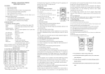
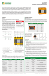
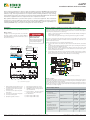
isoPV
Installation Bulletin / Reference Guide
TM
This document is intended as a reference guide for installing and using a BENDER isoPV ground fault
detector and AGH-PV voltage coupler for ungrounded solar (PV) arrays. This document includes installation, setup, and usage instructions. For complete details, including installation, setup, settings,
and troubleshooting, refer to the isoPV user manual, document number TGH1454en. This document is
intended as a supplement and not a replacement to the complete user manual.
Only qualified maintenance personnel shall operate or service this equipment. These instructions
should not be viewed as sufficient for those who are not otherwise qualified to operate or service this
equipment. This document is intended to provide accurate information only. No responsibility is assumed by BENDER for any consequences arising from use of this document.
Installation
Wiring - Multiple isoPV Devices in Arrays with a Common Bus
Mounting
The isoPV and AGH-PV are designed for DIN rail mounting.
Only one isoPV detector at a time may be online and measuring in a complete isolated system.
Arrays connected to a common bus, which may or may not be connected simultaneously, require special connections in order to ensure that only one device is on at a time. These requirements may be accomplished in one of two ways:
Wiring - General
See figure 1 for basic wiring schematic. Use of the AGHPV voltage coupler is required. Use minimum AWG 24,
maximum AWG 12 wire. For more information, refer to
the isoPV user manual.
! DANGER
HAZARD OF ELECTRIC SHOCK,
EXPLOSION, OR ARC FLASH
• Disconnect all power before servicing.
• Observe all local, state, and national
codes, standards, and regulations.
2
4
3Ø AC System, W/O N
1Ø AC System
Un
3
5
3Ø AC System, W/ N
DC System
•
Option 1: Connecting each device’s F1/F2 standby terminals and manually controlling the
switching with control logic
Option 2: Automating the switching by connecting each device together via RS-485
•
For option 1, closing the F1/F2 terminal set puts the device into standby mode. Using control
logic from the tiebreaker will allow for manual control to ensure that only one device is on
when the tiebreaker is closed.
Option 2 automates the process. Complete the following steps:
1. Connect each isoPV in series with each other via the “A” and “B” terminals. Use RS-485
cable.
2. The devices at the beginning and the end of the chain require activating the termination
resistor. Switch the “Ron” DIP switch to “ON.”
3. Each device requires a unique communication address. Under the menu option “COM
SETUP > Addr.” set one device to address 1. Set the address for each other device sequentially. Each address must be unique.
4. For each device, under the menu option COM SETUP > ISONet, set this option to “ON.” This
setting automates the process of ensuring only one device is measuring at any time. See
the reverse side of this document for more information on menu settings.
Un
Solar array 1
6
1
Solar array 2
Grid transformer
Figure 2 - Using the F1/F2 standby terminals with two isoPV devices and two arrays on a common bus
7
8
9
10
11
12
13
Figure 1 - isoPV and AGH-PV wiring diagram
Wiring - Contacts
Using a normally closed or normally open contact utilizes two factors: wiring out of the proper
terminal, and setting the respective contact to normally energized or deenergized operation.
Refer to the chart below for relay conditions.
The energized state of the contact may be changed by setting options ISO SETUP > K1 and ISO
SETUP > K2. In the device’s settings, option “N/O” refers to normally deenergized, and option
“N/C” refers to normally energized.
External supply voltage; 6A fuse recommended for internal device protection
7.
External TEST terminal, N/O contact
8.
External RESET terminal, N/O contact
2.
Connection to three-phase AC system
without neutral
Device Relay Conditions
9.
STANDBY terminals: Closing F1/F2 will
stop measurements
Relay Operation Setting
Device Alarm State
3.
Connection to three-phase AC system
with neutral
10. Analog outputs: 0... 400 μA on standard
version, 0/4... 20 mA on “B” version
4.
Connection to single-phase AC system
11. RS-485 interface
5.
Connection to DC system
Normally deenergized mode (N/D)
Non-failsafe mode
“N/O” in device settings menu
12. Alarm relay K1: SPDT contact
6.
Equipment ground connection
13. Alarm relay K2: SPDT contact
1.
K1 STATE
K2 STATE
Power ON, normal state (no alarms)
11-12 CLOSED
11-14 OPEN
21-22 CLOSED
21-24 OPEN
Energized in the alarm state
Power OFF
11-12 CLOSED
11-14 OPEN
21-22 CLOSED
21-24 OPEN
Relay will switch when the alarm is
activated.
Power ON, alarm state
11-12 OPEN
11-14 CLOSED
21-22 OPEN
21-24 CLOSED
Normally energized mode (N/E)
Failsafe mode
“N/C” in device settings menu
Power ON, normal state (no alarms)
11-12 OPEN
11-14 CLOSED
21-22 OPEN
21-24 CLOSED
Energized in the normal state
Power OFF
11-12 CLOSED
11-14 OPEN
21-22 CLOSED
21-24 OPEN
Relay will switch when the alarm is
activated, or when supply voltage
to the device is lost.
Power ON, alarm state
11-12 CLOSED
11-14 OPEN
21-22 CLOSED
21-24 OPEN
Bender Inc. • USA: 800.356.4266 / 610.383.9200 / [email protected] • Canada: 800.243.2438 / 905.602.9990 / [email protected] • www.bender.org
Document NAE1018370 • 10.2012 • © Bender Inc. • Page 1/1 • Side 1/2
isoPV
Installation Bulletin / Reference Guide
TM
Menu Structure Flow Chart
Front Panel Display
Figure 5 shows the structure of the menu built into the isoPV. The menu is used for viewing
alarms, viewing the status of the system, and making any necessary settings changes.
Use the supplied gray boxes to take note of applied settings for future reference. Note that
some settings do not have more than one selectable option - these are special options tuned
specifically for PV systems.
Menu or settings option
Settings option essential for proper operation
1
1. EXIT
2. HISTORY INFO
3. ISO SETUP
1. Exit
2.Alarm1
200 Ω... 100 kΩ
3. Alarm2
200 Ω... 100 kΩ
4. K1
N/O-T N/C-T
N/C N/O Flash
5. K2
N/O-T N/C-T
N/C N/O Flash
Memory
on
7. M+/M-
0-20 mA
4-20 mA
7. M+/M-: Ri
28kΩ
PV
3. Ce max
2000μF
4. Measure
AMP3
6
7
INFO / ESC key: Displays system information / goes back a step in menu
5.
LED “ALARM 1”: Illuminates when alarm
1 is active.
2.
TEST / UP key: Initiates self-test / moves
up in menu
6.
LED “ALARM 2”: Illuminates when alarm
2 is active.
3.
RESET / DOWN key: Resets device when
latching mode is active / moves down
in menu
7.
LED “ERROR”: Illuminates when a device
error has occured.
4.
MENU / ENTER key: Opens the main
menu / confirms changes in menu
•
Ensure that all menu options in red in the menu structure flow chart are set correctly.
Incorrect settings may lead to improper readings. For alarm trip values, use the factory
defaults when possible.
•
Use the following guidelines when setting the measuring principle under the ISO
ADVANCED > Measure menu option:
5. Autotest
24 no 01
6. Clock
00:00
7. Date
dd.mm.yy
•
AMP4
•
Use option “AMP3” for arrays with mono- or polycrystalline solar panels
•
Use option “AMP4” for arrays using thin-film solar panels
Options ISO SETUP > K1 and ISO SETUP > K2 refer to the energized state of the output
relays K1 and K2 during operation. Refer to the section “Wiring - Contacts” on the reverse side of this document for more information. The menu options stand for:
00:00 ... 23:00
•
N/C: Normally energized operation (failsafe mode)
•
N/O: Normally deenergized operation (nonfailsafe mode)
•
N/C-T: Normally energized operation, switches during self-test
•
N/O-T: Normally deenergized operation, switches during self-test
•
Flash: During alarm, contact switches app. every 2 seconds
2. Addr.
1 ... 30
Analog Outputs
3. ISONet
on off
4. ISO Monitor
1 ... 30
IsoPV models feature a 0 - 20 mA or 4 - 20 mA output, selectable in the main menu under ISO
SETUP > M+/M-. Under menu option ISO SETUP > M+/M-: Ri, the midpoint of the equation
may be set to 28 kΩ or 120 kΩ. When using an externally connected analog meter, ensure the
midpoint setting is the same as the external meter. For integrating into control systems, use
the midpoint value appropriate for the system’s requirements.
1. Exit
6. PASSWORD
2. Password
000 ... 999
3. Status
on off
0 - 20 mA output
1. Exit
7. LANGUAGE
English Deutsch
2. Text
RF
I
RI
Insulation resistance in kΩ
Current output in mA
Midpoint setting
RF
I
RI
Insulation resistance in kΩ
Current output in mA
Midpoint setting
4 - 20 mA output
8. SERVICE
Figure 5 - isoPV menu flow chart
Dimensions
Ordering Information
Dimensions in inches (mm).
2.9” (74)
3.2” (81)
Ø 0.18”
(4.5)
0.2”
(5)
4.4” (111)
2.4” (60)
4.1”
(104)
2.8” (71)
4.4” (112.5)
4.1”
(105)
5
1. Exit
5. COM SETUP
4.1”
(105)
4
1.
120kΩ
2.AGH
8. Test
3
Device Setup Tips
off
1. Exit
4. ISO ADVANCED
2
Ordering Information
Part No.
iso-PV-327
with AGH-PV
iso-PV-335
with AGH-PV
System Voltage
3(N)AC 0…793 V /
DC 0…1100 V
3(N)AC 0…793 V /
DC 0…1100 V
Supply Voltage
DC 19.2…72 V
Ordering No.
B 9106 5132W
AC 88…264 /
DC 77…286 V
B 9106 5133W
3.6” (91)
Screw mounting: Ø 0.22” (5.5)
Figure 3 - isoPV dimensions in inches (mm)
Figure 4 - AGH-PV dimensions in inches (mm)
Technical Data
Refer to isoPV series user manual (document TGH1454en) or isoPV series datasheet (document
NAE1012370) for detailed technical information.
Bender Inc. • USA: 800.356.4266 / 610.383.9200 / [email protected] • Canada: 800.243.2438 / 905.602.9990 / [email protected] • www.bender.org
Document NAE1018370 • 10.2012 • © Bender Inc. • Page 1/1 • Side 2/2