1
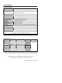
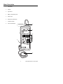
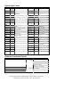
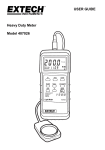
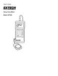
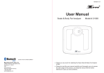
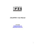
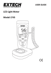
User's Guide
Heavy Duty Meter
Model 407026
99 Washington Street
Melrose, MA 02176
Phone 781-665-1400
Toll Free 1-800-517-8431
Visit us at www.TestEquipmentDepot.com
Back to the Extech 407026 Product Page
Introduction
Congratulations on your purchase of the Extech Heavy Duty Light Meter. This light meter
offers selectable lighting types, data record/recall, relative display mode, and PC interface.
This professional meter, with proper care, will provide years of safe reliable service.
Specifications
General Specifications
Circuit
Custom one-chip LSI microprocessor circuit
Display
3-1/2 digit (2000 count) LCD display with contrast adjustment
Measurement ranges
LUX: 0 to 50,000 LUX (3 range); Fc: 0 to 5000 Fc (3 range);
Relative mode: 0 to 1999%
Data Hold
Freezes displayed reading
Lighting Types
Sodium, Daylight/Tungsten, Fluorescent and Mercury
Sensor Structure
Cosine/color corrected photo-diode meets C.I.E.
Memory Store/Recall
Records/Recalls Max/Min/Avg readings
Sample rate
0.4 seconds (approx.) per reading
Zero Adjust
Push-button procedure
Auto Power Off
After approx. 10 minutes
Data Output
RS-232 PC serial interface (optional software/cable PN 407001)
Operating conditions
32 °F to 122 °F (0 °C to 50 °C); <80% RH
Power Supply
9V battery
Power consumption
Approx. 5 mA DC. (approx. 200 hr battery life)
Weight
0.71 lbs. (320 g)
Dimensions
Instrument: 7.1 x 2.8 x1.3" (180 x 72 x 32 mm)
Sensor: 3.3 x 2.2 x 0.7" (85 x 55 x 17.5 mm)
Range Specifications
Measurement
LUX
Foot Candles
Relative mode
Range
2,000 LUX
Display
0-1,999 LUX
Resolution
1 LUX
20,000 LUX
1,800-19,990 LUX
10 LUX
50,000 LUX
18,000-50,000 LUX
100 LUX
200 Fc
0-186.0 Fc
0.1 Fc
2,000 Fc
167-1,860 Fc
1 Fc
5,000 Fc
1,670-5,000 Fc
0-1999%
Accuracy
± (4% + 2 digits)
of full scale
10 Fc
1%
Note: The accuracy specification above applies to calibration performed using a precision
O
standard incandescent tungsten light source of 2856 K with meter on the tungsten setting.
Test Equipment Depot, 99 Washington Street, Melrose, MA 02176
781.665.1400 | 800.517.8431 | Fax: 781.665.0780
3
Model 407026 Version 2.3 January 2004
Meter Description
1
LCD Display
2
Keypad
3
Light sensor
4
Battery compartment (rear)
5
Sensor input
6
RS-232 PC Interface jack
7
Protective Holster
8
LCD Contrast Adjust
6
5
7
1
8
2
4
3
4
Model 407026 Version 2.3 January 2004
Operation
Meter Power and Automatic Power Off
1. Press the POWER button to turn the meter on. If the display does not switch on, check
the 9V battery.
2. Press the POWER button again to turn the meter off.
3. The meter has an automatic power off feature that conserves battery energy. After 10
minutes the meter automatically shuts off. To defeat this feature, press the RECORD
button to put the meter in the recording mode.
Display ZERO Calibration
Please perform a zero calibration before each use. This will ensure the highest accuracy.
1. Place the sensor cover over the light sensor, effectively blocking all light to the sensor.
2. Select the 2,000 LUX range using the RANGE switch.
3. Press the ZERO button. The reading should be zero.
4. Remove the sensor cover from the light sensor and proceed.
Selecting the unit of measure
Press the LUX/Fc button to select the desired unit of measure. The display icons will reflect
the current setting.
Selecting a light source
Select the type of lighting to be measured by pressing the LIGHT SOURCE button. The
display will indicate the lighting type icon (see icon list below).
L = Tungsten/Daylight (use this setting when calibrating with a Tungsten lamp)
F = Fluorescent
S = Sodium
C = Mercury
Note: For Halogen and Metal Halide light use the Tungsten setting
Taking Measurements
Hold the light sensor in the area where light is to be collected. The light being measured
must encompass the entire surface of the light sensor dome (pin point lighting such as with
LED light cannot be measured).
The display will indicate the light intensity value in LUX or Foot candles (Fc). Note that
since the main display area is limited to a reading of ‘1999’, the right-most digit in the
20,000 LUX and 5,000 Fc ranges appears on the lower LCD line. In the 50,000 LUX range,
the last two digits appear on the lower LCD line
It may be necessary to adjust the display contrast due to a change in viewing angle or
voltage drift. Use the LCD Contrast adjustment located on the right side of the meter to set
the preferred contrast.
Display Range Selection
Take a measurement starting at the highest range and then work down using the RANGE
switch. If the display shows dashes along the top of the reading area (
), the input
exceeds the maximum value for the selected range; select a higher range. If the display
shows dashes along the bottom of the reading area (
), the input is too low; select a
lower range.
5
Model 407026 Version 2.3 January 2004
Data Hold
While measuring, press the HOLD button to freeze the reading. The LCD will display D.H.
indicating that the Data Hold function is engaged. Press HOLD again to return to normal
operation.
Relative % Mode
In the RELATIVE mode of operation, the meter displays light level as a comparison to a
reference value. The reference value is stored by pressing the ‘%’ button while the desired
light level reference is on the display. When the button is pressed, ‘100%’ will be displayed
and the ‘%’ icon will appear.
After the ‘%’ button is pressed, light measurements will be displayed as a percentage of
the reference value. For example, if the light level reference is 1000 LUX, a display of 500
LUX will be represented as 50%. Further, a light level of 250 LUX will display as 25%. Use
the equation below:
Light measurement
Display % = --------------------------------------------------------------------------- X 100
Stored reference light measurement
Press the ‘%’ button again to return to normal operation.
Maximum (MAX), Minimum (MIN), and Average (AVG) readings
The meter can keep track of the highest, lowest, and average readings for later recall.
1. Press the RECORD button to start tracking the MAX, MIN, and AVG readings. The
REC display will switch on.
2. When desired, press the RECALL button.
3. The MAX display icon appears next to the REC display icon. The reading shown is the
highest reading encountered since the RECORD button was pressed.
4. Press RECALL twice more to view the MIN and AVG readings.
5. Press the RECORD button to return to normal operation.
RS-232 PC Interface
This meter is equipped with a RS-232 serial data port. This interface is for use with the
Extech Data Acquisition Software (Part number 407001) and enables the user to capture,
store and display readings on a PC. Contact Extech or refer to the 407001 user manual for
details on the PC interface.
Battery Replacement
When the low battery indicator appears (LBT), replace the battery as soon as possible.
Reliable readings can be obtained for several hours after the first appearance of the low
battery indication. To replace the battery:
1. Remover the meter's rubber protective holster.
2. The battery compartment is located on the lower back of the meter. Pry the battery
compartment cover off using a small coin or screwdriver and remove the battery.
3. Replace the 9V battery and reinstall the cover.
4. Ensure that the battery cover is secured after replacing the battery.
99 Washington Street
Melrose, MA 02176
Phone 781-665-1400
Toll Free 1-800-517-8431
Visit us at www.TestEquipmentDepot.com
Back to the Extech 407026 Product Page
Typical Light Levels
Lux
Foot
Candles
20-75
2-7
75-150
7-15
Lux
Foot
Candles
Emergency Stairs,
Warehouse
100-150
10-15
Washing
Exit/Entrance Passages
150-200
15-20
Recreational Activities
Drawing Room, Table
Factories
Home
150-300
15-30
Packing Work
200-300
20-30
300-750
30-75
Visual Work: Production Line
300-500
30-50
Makeup
750-1,500
75-150
Typesetting: Inspection Work
500-1,500
50-150
Reading, Study
1,5003,000
150-300
Electronic Assembly, Drafting
1,000-2,000 100-200
75-100
7-10
Office
Sewing
Restaurant
Indoor Emergency Stairs
75-150
7-15
Corridor Stairs
100-200
10-20
Corridor Stairs
150-300
15-30
Entrance, Wash Room
200-750
20-75
Conference, Reception Room
300-750
30-75
Cooking\Dinning Room
750-1,500
75-150
Clerical Work
750-1,500
75-150
Show Window
1,5002,000
150-2000 Typing, Drafting
75-150
7-15
Indoors
30-75
3-7
Emergency Stairs
Store
Hospital
150-200
15-20
Corridor/Stairs
75-100
7-10
Stairs
200-300
20-30
Reception
100-150
10-15
Sick Room,
Warehouse
300-500
30-50
Display Stand
150-200
15-20
Waiting Room
500-750
50-75
Elevator
200-750
20-75
Medical Exam Room
750-1,500
75-150
Show Window, Packing Table
750-1,500
75-150
Operating Room
1,5003,000
150-300
Storefront, Show Window
5,00010,000
500-1000 Eye Inspection
Common Conversion Factors
Illuminance (Visible Flux Density)
1 lm/m2 =
1 lux (lx)
10-4 lm/cm2
10-4 phot (ph)
9.290 x 10⁻² lm/ft2
Luminance (Visible Flux Density per Solid Angle)
Luminous Intensity (Visible Flux per Solid Angle)
Luminous Flux ( Visible Flux)
9.290 x 10⁻² foot-candles
2
1 lm/m /sr = 1 candela/m2
1 lm/sr = 1 candella
1 lumen (lm) = 1.464 x 10⁻³ watts @ 555 nm
Test Equipment Depot, 99 Washington Street, Melrose, MA 02176
781.665.1400 | 800.517.8431 | Fax: 781.665.0780