1
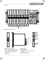
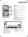
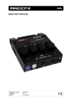
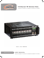
12 Channel 19” Dimmer Pack
Order code: BOTE45
www.prolight.co.uk
USER MANUAL
S A F E T Y WA R N I N G S
WARNING
FOR YOUR OWN SAFETY, PLEASE READ THIS USER MANUAL CAREFULLY
BEFORE YOUR INITIAL START-UP!
CAUTION!
Keep this equipment away from rain,
moisture and liquids.
SAFETY INSTRUCTIONS
Every person involved with the installation, operation & maintenance of this
equipment should:
-
Be competent
-
Follow the instructions of this manual
CAUTION! TAKE CARE USING THIS EQUIPMENT!
HIGH VOLTAGE-RISK OF ELECTRIC SHOCK!!
Before your initial start-up, please make sure that there is no damage caused during
transportation. Should there be any, consult your dealer and do not use the
equipment.
To maintain the equipment in good working condition and to ensure safe operation, it is necessary
for the user to follow the safety instructions and warning notes written in this manual.
Please note that damages caused by user modifications to this equipment are not
subject to warranty.
S A F E T Y WA R N I N G S
IMPORTANT:
The manufacturer will not accept liability for any resulting damages caused
by the non-observance of this manual or any unauthorised modification to the
equipment.
• Never let the power-cable come into contact with other cables. Handle the power-cable
and all mains voltage connections with particular caution!
• Never remove warning or informative labels from the equipment.
• Do not open the equipment and do not modify the equipment.
• Do not connect this equipment to a dimmer-pack.
• Do not switch the equipment on and off in short intervals, as this will reduce the
system’s life.
• Only use the equipment indoors.
• Do not expose to flammable sources, liquids or gases.
• Always disconnect the power from the mains when equipment is not in use or before
cleaning! Only handle the power-cable by the plug. Never pull out the plug by pulling the
power-cable.
• Make sure that the available voltage is between 220v/240v.
• Make sure that the power-cable is never crimped or damaged. Check the equipment and
the power-cable periodically.
• If the equipment is dropped or damaged, disconnect the mains power supply immediately.
Have a qualified engineer inspect the equipment before operating again.
• If the equipment has been exposed to drastic temperature fluctuation (e.g. after
transportation), do not switch it on immediately. The arising condensation might damage
the equipment. Leave the equipment switched off until it has reached room temperature.
• If your product fails to function correctly, discontinue use immediately. Pack the unit
securely (preferably in the original packing material), and return it to your Prolight dealer
for service.
• Only use fuses of same type and rating.
• Repairs, servicing and power connection must only be carried out by a qualified
technician. THIS UNIT CONTAINS NO USER SERVICEABLE PARTS.
• WARRANTY; One year from date of purchase.
OPERATING DETERMINATIONS
If this equipment is operated in any other way, than those described in this manual,
the product may suffer damage and the warranty becomes void.
Incorrect operation may lead to danger e.g.: short-circuit, burns and electric shocks etc.
Do not endanger your own safety and the safety of others!
Incorrect installation or use can cause serious damage to people and property.
OVERVIEW
Overview:
POWER
P
O
W
E
R
A
C
T
I
V
E
P
O
W
E
R
A
C
T
I
V
E
P
O
W
E
R
A
C
T
I
V
E
P
O
W
E
R
A
C
T
I
V
E
P
O
W
E
R
A
C
T
I
V
E
P
O
W
E
R
A
C
T
I
V
E
P
O
W
E
R
A
C
T
I
V
E
P
O
W
E
R
A
C
T
I
V
E
P
O
W
E
R
A
C
T
I
V
E
P
O
W
E
R
A
C
T
I
V
E
P
O
W
E
R
A
C
T
I
V
E
P
O
W
E
R
DMX
A
C
T
I
V
E
MODE
BACK
DMX IN
DMX OUT
12 x Dimmer module
Dimmer Module overview:
1
P
O
W
E
R
A
C
T
I
V
E
P
O
W
E
R
A
C
T
I
V
E
LOAD AC OUTPUT
16A MAX
1
2
3
4
VAC INPUT
N NEUTRAL
CONTROL INPUT
4-12V DC
GND
1, Module mounting holder
Pull the holder to change the module.
Press to replace. The dimmer pack
must be disconnected from the
mains first.
2, AC Indicator
3, TRIG Indicator
4, Circuit breaker
Engages in the event of overload or
short circuit.
5, Ventilation openings
5
OVERVIEW
Control module:
6, DMX Indicator
This Lights up when the unit is receiving a DMX
signal.
7, Power Indicator
This lights up as soon as the unit is supplied with
power.
8, LCD
This displays all of the menu functions and values
9, UP Button
This button is used for editing through the mode
functions.
10, Mode Button
This button is used for advancing to the
next mode.
11, Down Button
This button is used for editing through the mode
functions.
12, Back Button
This button is used to exit from the current
chosen mode
13, DMX Out Socket
This is a 3-pin XLR output socket and is used for
connecting an additional dimmer pack.
14, DMX In Socket
This is a 3-pin XLR input socket and is used for
connecting your DMX controller.
Rear pannel:
15
15, DMX Connectors
You can route the DMX control
signal to additional dimmer packs
by using the 3-pin DMX OUT
XLR connector. The 3-pin XLR
input is for connecting DMX -512
control signals. You can connect
your DMX controller here.
17
16
16, Outputs
Cable slot for connecting the lamps
17, Power Supply
This cable slot is used for connecting the
power supply
I N S TA L L AT I O N
Installation:
Install the unit on a plane surface or alternately install it in a 19” rack.
Rack Installation:
This unit is built for 19” racks (483mm). The rack you use should be a Double-Door-Rack where
you can open the front panel and the rear panel. The rack should be provided with a cooling fan,
When mounting the controller into the rack, please make sure that there is enough space around
the unit so that the heated air can be passed on. Steady overheating will damage your unit.
You can fix the controller with four screw (M6) in the rack.
Connecting the lamps:
!CAUTION!
Unplug the mains lead before connecting the lamps
Connect your loads via the connectors. The maximum load per channel is 3680W. Please note
that the maximum current of 189A must never be exceeded!
Connection with the mains:
!DANGER TO LIFE!
The electric connection must only be carried out by a
qualified electrician!
The occupation of the connection-cables is as follows:
The earth has to be connected!
If the unit will be directly connected with the local power supply network, a disconnection switch
with a minimum opening of 3mm at every pole has to be included in the permanent electrical
installation.
The unit must only be connected with an electric installation carried out in compliance with the IEC
standards. The electric installation must be equipped with a Residual Current Device (RCD) with a
maximum fault current of 30mA.
O P E R AT I O N
Operation:
Setting into operation:
After connecting the 12 Channel 19” Dimmer Pack to the mains, the unit starts running.
The POWER indicator lights up. “Transcension” and “WELCOME TO USE” is displayed on the
LCD screen. During this indication, the unit is conducting a self-test and recalls previous memory
records afterwards; “Running Progxx” or “DMX MODE”. If the unit receives a DMX signal, the
DMX indicator lights up. You are now in the main menu.
Navigation through he menu:
In the following chapters every menu is described in detail. Please use the buttons below the LCD
to navigate through the menu and for data input. The underscore on the display indicates your
position in the menu.
By pressing the UP/DOWN buttons you can select the individual menus (DMX Fail, DMX addr,
Preheat, Max level, Curve and manual). Enter one of the menus by pressing the MENU button.
You are now in the corresponding sub menu. By using the UP/DOWN buttons you can set the
parameters. The values can be increased or decreased by 1. Keep the UP/DOWN buttons
pressed for two seconds to change the values faster. Exit the menu by pressing the BACK button.
If there are no buttons pressed in the sub menu within 20 seconds the unit will automatically exit to
the main menu.
Button
Function
MENU
UP
DOWN
BACK
Enter the menu, confirm
Navigate up, data input
Navigate down, data input
Exit the menu
DMX Fail (reaction when DMX signal fial to come):
Here you can determine the unit’s reaction when the DMX control signal transmission
is interrupted.
Display
Function
DMX Fail
Prog08
Selects a built-in programme (1-12), that is to run when the DMX signal transmission is
interrupted. DMX signal are always prior to built-in programmes.
Speed
Value=00.4S
The speed of the programmes can be set in the sub menu (00.1-20.0S
O P E R AT I O N
DMX addr (addressing, DMX operating modes):
Depending on the operation mode Block or single, you can set one or several DMX addresses for
an individual channel or several channels.
Display
Function
Button
DMX addr
Block
(Block) The entire dimmer operates on one DMX start
address. Set an address for the first channel in the sub menu (001-512).
Every next channel gates a DMX address which is one number higher.
MENU
UP/DOWN
BACK
Start addr
Value=(044)
DMX addr
Single
DMX addr CH(01)
Value=(023)
(SINGLE) Set a start address in the sub menu for each of the 12 channels individually (001-512). Two or more channels can share the same
address. Use the MENU button to
navigate from “DMX addr CH (XX)” to “Value=(XX)”.
MENU
UP/DOWN
BACK
MENU
UP/DOWN
BACK
Preheat:
Here you can determine the preheat value, which is then continuously run to the unit’s connected
in series (e.g. theatre spots). This function results in lower start-up current requirement and
prolongs the life of the illuminants. The preheat value can be assigned to all 12 channels in mode
All or to each channel individually in mode Single. The preheat function cannot be used in switch
mode.
Display
Function
Button
Preheat All
Value=(20%)
(ALL) Set the preheat value for all 12 channels (0-50%).
MENU
UP/DOWN
BACK
Preheat CH(01)
Value-(023%)
(SINGLE) Set the Preheat value for each of the 12 channel individually
(0-50%). Use the MENU button to navigate from “Preheat CH (XX)” to
“Value=(XX)”.
MENU
UP/DOWN
BACK
MENU
UP/DOWN
BACK
Max Level (channel limitation)
Here you can set an upper limit for the control signal of each individual channel. The limiter
function, too, prolongs the life of your illuminants. Limiting the upper range of control voltage
protects from voltage oscillations and overdrive. Depending on the mode, you can set a value for
all channels or for each channel individually. Max level function cannot be used in switch mode.
Display
Function
Button
Max level
All
(ALL) Limits all channels to a maximum level (0-100%).
MENU
UP/DOWN
BACK
Max level CH(01)
Value-(023%)
(SINGLE) Each channel can be preheated individually (0-100%). Use the MENU
UP/DOWN
MENU button to navigate from “Max level CH” to “Value=(XX)”.
BACK
MENU
UP/DOWN
BACK
O P E R AT I O N
Curve (transmission characteristic):
100%
Here you can set up the transmission characteristic of your Dimmer
Pack. You can determine how control voltage (fader movement on the
controller) is transmitted to the units connected in series. Depending on
the mode, you can adjust a curve for all channels or for each
channel individually.
L
0%
50%
S
0%
50%
100%
(L) The default mode is “liner”. Here the ratio of input value and
output level is linear, i.e. when the fader on the controller is moved up
or down, the light intensity of the lamp connected in series changes
directly proportionate to the fader movement.
(S) When set to switch mode, the respective channel works like an electronic relay. This way, you
can control fog machines, motors and other effects units (when the control voltage reaches 50% or
more of a previously set value, the channel is switched on; when it falls below 50%, the
channel is switched off again). The preheat and Max level functions cannot be used in switch mode.
Display
Function
Button
Curve
All
(ALL) Define one curve for all channels (linear or switch)
MENU
UP/DOWN
BACK
(SINGLE) Adjust transmission curves for each individual channel. (Linear
or Switch). Use the MENU button to navigate from “Curve CH (XX)” to
“Value=(X)”.
MENU
UP/DOWN
MENU
UP/DOWN
BACK
Curve All
Value=(linear)
Curve CH(01)
Value=(linear)
Curve CH(01)
Value=(Switch)
Manual (manual light control):
In manual mode, the Dimmer Pack can be used without an external controller and the channels
can be adjusted manually via the buttons below the LCD screen. Depending on the mode, you can
adjust a value for all channels or for each channel individually. The manual control cannot be used
in DMX mode. The values set in the menu “Manual” do not affect the built-in programmes (DMX
Fail function), however, they must be within the upper limit, set in the menu “Max level” (channel
limitation). Contrary to the DMX mode (DMX Fail functions), the manual mode has no power
failure function.
Display
Function
Button
Manual
All
(ALL) Assign a value to all 12 channels (0-100%)
MENU
UP/DOWN
MENU
UP/DOWN
BACK
Manual All
Value=(20%)
Manual CH(01)
Value=(23%)
(SINGLE) Assign a value to each of the 12 channels individually (0100%). Use the MENU button to navigate from “Manual CH (XX)” to
“Value=(XX)”.
MENU
UP/DOWN
MENU
UP/DOWN
MENU
UP/DOWN
BACK
S P E C I F I C AT I O N S
Technical Specifications:
Power Supply....................................................................................................................240V - 50Hz
Max. power output..................................................................................................................43470W
Max. current...................................................................................................................................189A
Max output/channel..................................................................................................................3680W
Max current/channel......................................................................................................................20A
Number of control channels............................................................................................................12
Intergrated programmes..................................................................................................................12
Fuse.........................................................................................................................12 x C 20A 240V
DMX output..................................................................................................3-pin female XLR socket
DMX input........................................................................................................3-pin male XLR socket
Outputs
DPMX-1216................................................................................................................Pole connectors
DPMX-1216 S...............................................................................................................Safety sockets
DPMX-1216 CEE.............................................................................................................CEE sockets
DPMX-1216 MP............................................................................................................16-pin sockets
Dimensions.........................................................................................................482 x 485 x 176mm
Minimum mounting depth........................................................................................................500mm
Weight.......................................................................................................................27Kg