1
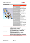
AP4050 User's Manual Revision: 03/2010 back cover Rev: 03/2010 Contents 1 General information.....................................................................................................................................3 1.1 Introduction............................................................................................................................................ 3 1.2 Key features...........................................................................................................................................3 1.3 Normative references............................................................................................................................ 3 1.4 Prearrangements at customer's expense.............................................................................................. 5 1.4.1Requirements to the site of installation........................................................................................... 5 1.5 Address for support and maintenance................................................................................................... 5 1.6 Conventions used in this manual........................................................................................................... 6 2 Technical data.............................................................................................................................................. 7 2.1 Power and air supply............................................................................................................................. 7 2.2 Specifications.........................................................................................................................................7 2.3 Performances........................................................................................................................................ 8 2.4 Noise levels........................................................................................................................................... 8 2.5 Dimensional drawings............................................................................................................................9 2.6 Machine Layout................................................................................................................................... 10 3 Commissioning.......................................................................................................................................... 11 3.1 Applicator unpacking and transportation.............................................................................................. 11 3.1.1 Removing the applicator from the packaging...............................................................................12 3.1.2 Mounting the applicator on the support........................................................................................13 3.2 Assembling and preliminary operations............................................................................................... 14 3.2.1 Mounting the printer on the applicator......................................................................................... 14 3.2.2 Mounting the Filter/Regulator assembly...................................................................................... 15 3.2.3 Drilling the application plate......................................................................................................... 15 3.2.4 Stroke length adjustment............................................................................................................. 16 3.2.5 Tamp home adjustment................................................................................................................17 3.2.6 Roll support blades adjustment....................................................................................................18 3.2.7 Mounting the label stock.............................................................................................................. 18 3.2.8 Air assist adjustment.................................................................................................................... 20 3.2.9 Tamp speed adjustment...............................................................................................................21 3.3 Connections setup............................................................................................................................... 22 3.3.1 Printer setup................................................................................................................................ 22 4 Using the applicator.................................................................................................................................. 23 4.1 Intended use........................................................................................................................................ 23 4.2 Application mode................................................................................................................................. 23 4.2.1 Tamp-blow mode......................................................................................................................... 23 4.2.2 Tamp-on mode............................................................................................................................. 23 4.2.3 Blow-on mode..............................................................................................................................23 4.3 Safety equipments............................................................................................................................... 24 5 Instructions for the Operator.................................................................................................................... 25 5.1 Start and Stop functions.......................................................................................................................25 5.1.1 Switch On.................................................................................................................................... 25 5.1.2 Start............................................................................................................................................. 25 5.1.3 Stop............................................................................................................................................. 25 5.2 Functions menu................................................................................................................................... 26 5.2.1 Set down counter......................................................................................................................... 26 5.2.2 Rst label counter..........................................................................................................................26 5.2.3 Clock settings.............................................................................................................................. 26 5.2.4 Display settings............................................................................................................................26 5.2.5 Event counters.............................................................................................................................27 5.3 Select configuration............................................................................................................................. 27 5.4 Operation............................................................................................................................................. 28 6 Maintenance.............................................................................................................................................. 31 6.1 Daily maintenance............................................................................................................................... 31 6.2 Weekly maintenance............................................................................................................................31 6.3 Six-month maintenance....................................................................................................................... 31 6.4 Yearly maintenance............................................................................................................................. 31 Phoenix Italia - AP4050 User's Manual 1 Rev: 05/2010 7 Machine diagnosis.....................................................................................................................................32 7.1 Error handling...................................................................................................................................... 32 7.2 Troubleshooting................................................................................................................................... 33 8 Declaration of Incorporation..................................................................................................................... 35 Appendix A – Accessories........................................................................................................................... 36 A.1 Variable stroke sensor......................................................................................................................... 36 A.2 Low label sensor................................................................................................................................. 37 A.3 Three colors LED lamp........................................................................................................................38 Appendix B – Versions................................................................................................................................. 39 B.1 500mm stroke version......................................................................................................................... 39 B.2 Swing-arm version...............................................................................................................................40 B.2.1 General overview........................................................................................................................ 40 B.2.2 Swing-arm lengths and application plates................................................................................... 40 B.2.3 Dimensional drawings................................................................................................................. 40 B.2.4 Assembling the Swing-arm KIT................................................................................................... 42 B.2.5 Stroke regulation and home sensor calibration........................................................................... 42 2 Phoenix Italia - AP4050 User's Manual Rev: 03/2010 General information 1 General information 1.1 Introduction The Phoenix Italia AP4050 Applicator is designed to accommodate different types of print engines. For print engine operation, refer to the manufacturer’s Print Engine Manual. This chapter covers the purpose and scope of this manual, the conventions used to convey information and the manual outline. Customer Support information is located at the end of this chapter. For specific information about configuration and programming of the applicator, refer to the “AP4050 Programming and Interfacing Manual”. 1.2 Key features • Robust and corrosion resistant anodized aluminum and stainless steel construction. • Up to 60 labels per minute. • Stepping motor driven, tension arm controlled, unwinder-rewinder mechanism. • Direct blow, tamp blow and tamp on application. • Low force (< 50 N) on the application plate assures the operator safety. • Application plate exchangeable in few seconds. • Multiple trigger inputs, allowing separate print and apply activation. • Splash proof control panel with large, clearly visible 2x20 characters display. • USB port for diagnostics, remote control, firmware upgrade and configuration. • Universal power supply 90-264 VAC, with switch off driven by the printer. • Optional three colors status lamp. • Optional end of paper sensor. • Solid state vacuum and pressure sensors. • Festo pneumatics 1.3 Normative references DIRECTIVE 98/37/EC of 22 June 1998 on the approximation of the laws of the Member States relating to machinery DIRECTIVE 2006/95/EC of 12 December 2006 on the harmonization of the laws of Member States relating to electrical equipment designed for use within certain voltage limits DIRECTIVE 2004/108/EC of 15 December 2004 on the the laws of the Member States relating to electromagnetic compatibility and repealing Directive 89/336/EEC Phoenix Italia - AP4050 User's Manual 3 General information 4 Rev: 05/2010 Stand. body Reference Title of standard Ratified year CEN EN ISO 12100-1:2003 Safety of machinery — Basic concepts, general principles for design — Part 1: Basic terminology, methodology (ISO 12100-1:2003) 2005 CEN EN ISO 12100-2:2003 Safety of machinery — Basic concepts, general principles for design — Part 2: Technical principles (ISO 12100-2:2003) 2005 CEN EN ISO 13857:2008 Safety of machinery — Safety distances to prevent hazard zones being reached by upper and lower limbs (ISO 13857:2008) 2008 CENELEC EN 60204-1:1997 Safety of machinery — Electrical equipment of machines — Part 1: General requirements 1997 Phoenix Italia - AP4050 User's Manual Rev: 03/2010 General information 1.4 Prearrangements at customer's expense Any operation on the AP4050 Applicator should be performed only by trained personnel. Consider legally permissible minimum age! In principle the labeler should be used only by persons who have received a complete briefing. Trainees or personnel during the briefing etc. are allowed to perform tasks only supervised by an experienced person. 1.4.1 Requirements to the site of installation • Closed and clean room • Leveled surface, solid floor. • An adequate support where to fix the machine. • Low vibration environments • Adequate illumination • No direct irradiation from sun light or heaters • The machine must not operate in areas with electrostatic or magnetic fields. This can result into malfunctions of the controller or application troubles. • Appropriate air and power supply, according to the technical specifications (Ref. Chapter 2). 1.5 Address for support and maintenance Distributor/Integrator For any request, please contact your local distributor/integrator or the company who installed the unit. Phoenix Italia does NOT provide support to end-users. You should be prepared with the following information: • Fault description: give full details • The serial numbers of the machine: applicator, rewinder and display. • Exact circumstances when the error occurs For a complete list of Phoenix Italia authorized dealers, visit: www.phoenixitalia.it Phoenix Italia - AP4050 User's Manual 5 General information Rev: 05/2010 1.6 Conventions used in this manual Following is a brief list of the conventions used in this manual. Pay special attention to any procedure that may have one of the following symbols. Read all of the Caution and Warning instructions and follow them when performing the corresponding procedures. WARNING! THIS SYMBOL IS USED TO WARN USERS OF DANGER FROM (POSSIBLE) ELECTRICAL SHOCK! READ ALL CAUTION STATEMENTS AND FOLLOW ALL THE INSTRUCTIONS TO AVOID A PERSONAL INJURY AND/OR EQUIPMENT DAMAGE. WARNING! THIS SYMBOL IS USED TO WARN USERS OF DANGER FROM (POSSIBLE) HURT OR PHYSICAL DAMAGE. READ ALL CAUTION STATEMENTS AND FOLLOW ALL THE INSTRUCTIONS TO AVOID A PERSONAL INJURY AND/OR EQUIPMENT DAMAGE CAUTION! THIS SYMBOL IS USED TO WARN USERS THAT MACHINE DAMAGE IS POSSIBLE IF ALL PROCEDURES ARE NOT FOLLOWED CAREFULLY. READ ALL NOTICE STATEMENTS AND FOLLOW ALL THE PROCEDURES CAREFULLY IN ORDER TO AVOID EQUIPMENT DAMAGE. 6 Phoenix Italia - AP4050 User's Manual Rev: 03/2010 Technical data 2 Technical data This chapter covers general and logistical functions regarding the machine and its usage. This includes information about air and power source specifications, illustrations of the primary working components, and illustrations of the various machine layouts. 2.1 Power and air supply The label applicator requires electrical power and compressed air. Regarding power data refer to the details on the rewinder cover. The compressed-air inlet is placed at the stroke unit bottom. For the connection use a flexible connection tube attached to a filter/regulator (included) which has to be controlled and emptied regularly. For more information see Chapter 6, Maintenance on page 28. The compressed air must be dry, clean and free from oil. Typical Air Pressure is 4-5 bar. The air supply pressure must always be greater than the highest pressure adjusted on the machine to avoid malfunctions. 2.2 Specifications 710x580x235mm not including the printer. (dimensions for the 250mm DIMENSIONS (LxHxW) stroke version: Ref. Chapter 2.5. Appendix A&B for details of other configurations) WEIGHT Base 250mm stroke version: 25 kg, not including the printer POWER SUPPLY 90-263 VAC, 48-63 Hz AIR SUPPLY Air Pressure: 5 bar, according to DIN ISO 8573-1 200 Nl/min, minimum flow rate requirement. Air Consumption: 0,8-1 liter per cycle of typical application ENVIRONMENT Temperature 10° - 35 °C Relative humidity from 20% to 90% not condensing Sato 8485/8490/8460 Sx PRINTER ENGINE Zebra 17x/110 PAX Datamax PE 4x, A-Class Avery DPMx PISTON STROKE From 0 to 240 mm standard, up to 590 mm option Phoenix Italia - AP4050 User's Manual 7 Technical data Rev: 05/2010 2.3 Performances LABEL SIZE max 120 x 170 mm. LABEL STOCK Up to 300 mm diameter, 76mm inner diameter. SPEED Up to 60 labels per minute. APPLICATION DISTANCE From 0 to 50 mm, depending by the label size. ACCURACY +/- 1 mm , for a flight distance smaller than 50% of the shortest side of the label. REWINDER Stepping motor driven, microprocessor controlled for a constant tension of the web. DISPLAY 2 x 20 characters backlit LCD CONTROLS [START], [STOP] , [Enter], [>], [<] keys 2.4 Noise levels At a distance of 1 meter from the workstations and 1,5 meter off the floor the following sound emissions were observed: < 72dB a-weighted < 80dB c-weighted 8 Phoenix Italia - AP4050 User's Manual Rev: 03/2010 Technical data 2.5 Dimensional drawings Dimensional drawing for the standard 250mm. Please refer to the Manual appendix for further drawings. Phoenix Italia - AP4050 User's Manual 9 Technical data Rev: 05/2010 2.6 Machine Layout 11 10 1. Display controller 2. Main plate 3. Unwinder 4. Dancer arm (unwinder) 5. Rewinder 6. Dancer arm (rewinder) 7. Printer (not supplied) 8. Air assist 9. Tamp Pad 10. Low Label sensor (optional) 11. Stroke Unit Phoenix Italia - AP4050 User's Manual Rev: 03/2010 Commissioning 3 Commissioning This chapter covers all the operation that could be done before the AC power and the compressed air are connected to the machine. All the procedures must be performed by an expert technician. 3.1 Applicator unpacking and transportation WARNING! THE APPROXIMATE WEIGHT OF THE PHOENIX ITALIA AP4050 APPLICATOR IS ABOUT 25KG PLUS THE WEIGHT OF THE PRINTER ENGINE. WARNING! THE STEEL BLADES MOUNTED ON THE PAPER ROLLS SUPPORT COULD BE RELATIVELY SHARP. DON'T PICK UP THE APPLICATOR HANDLING THESE PARTS WARNING! THE PAPER TENSION ARMS ARE QUITE DELICATE. DON'T PICK UP THE APPLICATOR HANDLING THESE PARTS. Phoenix Italia - AP4050 User's Manual 11 Commissioning Rev: 05/2010 3.1.1 Removing the applicator from the packaging Open the packaging and remove the applicator. Two technician should lift the applicator from the carton, grabbing it from the black faceplate. Place the applicator on an adequately stable work surface that is approximately 80 cm high and that can support at least 100 Kg. 12 Phoenix Italia - AP4050 User's Manual Rev: 03/2010 Commissioning 3.1.2 Mounting the applicator on the support If the applicator is installed on a machine stand, it must be able to support at least 100 kg and have a base that is large enough to prevent the machine from tipping over. When positioning the machine consider the following placement criteria: The AP4050 baseplate is equipped with a set of hole made to fit the most common commercial stands and standard aluminum profiles. (ref. Fig. 1.). The machine should be positioned the appropriate distance from the product. The extended tamp should not touch any part of the product as it passes by the machine if is not present the Variable Stroke option. The position of the machine should allow the operator to easily change labels and ribbon, and reach the printer keypad. Make sure that all the adjustment locks have been tightened after the machine has been correctly assembled and positioned. Keep in mind all points of the description "Intended Use" on chapter 4.1. Fig. 1: AP4050 fixing holes Phoenix Italia - AP4050 User's Manual 13 Commissioning Rev: 05/2010 3.2 Assembling and preliminary operations 3.2.1 Mounting the printer on the applicator Mount the printer on the applicator main plate as shown in the photo below, and fix it using the five supplied M5x10 screws. Connect the 15 poles printer cable to the printer and the “Printer” port on the back of the rewinder unit. Connect the supplied AC Power cable to the printer power input socket and on the Power OUT socket on the back of the rewinder unit. 14 Phoenix Italia - AP4050 User's Manual Rev: 03/2010 Commissioning 3.2.2 Mounting the Filter/Regulator assembly The filter regulator must be mounted with the tank vertical with the exhaust valve on the bottom. If it is necessary to install the FR group away from the applicator the tube between the FR and the applicator must not be longer than 1 m (∅8 mm). 3.2.3 Drilling the application plate The shipped application plate normally it is not drilled. To allow proper operation of the applicator, a series of holes, whose layout depends on label size, must be drilled on the application plate: through these holes the label will be kept on the plate by vacuum suction and then shot on the product by an air blast. The following rules must be observed to correctly prepare the application plate: 1. The holes must be entirely contained within the label footprint (if one or more holes are not completely covered by the label, vacuum suction will not work properly and the applicator will stop in error condition); 2. They should be organized in a nearly square grid having a pitch of 5 to 15 mm, depending on label size, leaving a 5 to 10 mm of distance from the label edges (in case of very elongated labels, different pitches may be used in the two directions); 3. Select the grid pitch to avoid that any hole results in correspondence of the output of the air pipe; the total number of holes may vary from 8 or 9 (2x4 or 3x3) for a very small label to 70 (10x7) for the biggest one (170x120 mm). 4. To obtain maximum performance in terms of precision and application distance, it is very important that the grid of holes results uniform and symmetrical on the label in both directions (take note of the effective position of the label on the application plate after having correctly loaded and aligned the paper on the printer). It is advisable to make a photocopy of the layout of the holes for future reference. The application plate must be mounted on the counter-plate using the supplied plate gasket by means of the 14 M4x10 mm conical head Allen screws supplied in the kit. Tighten the screws gently alternating the operation on the screws on opposite sides of the plate, Sealant is not requested and not suggested. NOTE: Never operate the applicator before drilling holes in the application plate. The total section of the drills must be larger than 15 sq. mm. Phoenix Italia - AP4050 User's Manual 15 Commissioning Rev: 05/2010 3.2.4 Stroke length adjustment The applicator is supplied with the maximum allowed stroke. In some applications, where it is necessary to have higher rate or where it is requested to trim the extension length, it is possible to reduce the stroke moving the stopper mounted on the slide bar internally to the applicator body. If the full stroke is restored, it is extremely important to leave free at least 10 mm on the bar where it is mounted, otherwise the damper can't work properly with the consequent impact of the piston on the cylinder bottom. This can cause a serious reduction of the life of the cylinder, beside the noise and the vibrations created by the improper operation. Photo 2: Maximum stroke lenght adjustment 16 Phoenix Italia - AP4050 User's Manual Rev: 03/2010 Commissioning 3.2.5 Tamp home adjustment The tamp home position is where the tamp pad receives the label after it has been printed. The tamp will then extend to apply the label to the product Fig 1: label on tamp positioning If the tamp pad is adjusted too low, the label will hit the edge of the pad and jam. If the tamp pad is adjusted too high, the label will be not positioned correctly onto the pad. For a proper operation, the tamp position must be trimmed 0.5 to 1 mm lower than the peeling blade. This adjustment may need to be changed when different label materials are used. Photo 3: Tamp home adjustment The height of the application plate in the retracted position is adjustable by means of a stopper the left bar of the slide, in order to align the tamp with the label peeling edge. If the stopper is moved it is important to check the proper operation of the home position sensor and eventually recalibrate its position. Phoenix Italia - AP4050 User's Manual 17 Commissioning Rev: 05/2010 3.2.6 Roll support blades adjustment Both the rewinder and the unwinder can handle cores with a nominal internal diameter of 3". The roll supports have three stainless steel blades whose position can be adjusted to compensate for the tolerance of the diameter of the core to guarantee a perfect grip. For a correct operation, it is necessary that the cores do not slide, otherwise the unwinder brake and/or the rewinder will not work properly. Although it is possible to rewind the web directly on the blades without any core, it is more practical to use one for an easier web unload. Photo 4: Roll support blades adjustment 3.2.7 Mounting the label stock After the adjustment of the roll blades, install the paper as shown in the Fig. 2. The web can be rewound directly or on an old label carton, for a quick discharge. Load the label roll on the blades of the inner unwind disk and up against the inner unwind disk. The label roll must be oriented so that the material passes through the print head with the label side up. Refer to your specific Print Engine Manual for more information on loading the label stock or print media into the printer. WARNING! THE STEEL BLADES MOUNTED ON THE PAPER ROLL SUPPORTS COULD BE RELATIVELY SHARP. BE CAREFUL WHEN INSERTING OR REMOVING LABEL ROLLS AND USE PROTECTION GLOVES. Peel off the first meter of labels from the label liner. Thread the label stock. Make sure that the inner edge of the label liner moves in a straight line from the inner unwind disk through the printer. Turn the rewind mandrel until all the slack is removed between the peeler bar and the rewind mandrel. (It’s good to have 2-3 wraps to start.) 18 Phoenix Italia - AP4050 User's Manual Rev: 03/2010 Commissioning Fig 2: Paper path Phoenix Italia - AP4050 User's Manual 19 Commissioning Rev: 05/2010 3.2.8 Air assist adjustment Proper adjustment of the air-assist system is extremely important for reliable operation of the applicator: the label must be kept adherent to the application plate during printout and, when it has been completely detached from the backing paper, it must stay flat, covering all the holes, otherwise the vacuum suction cannot establish enough depression to keep the label firmly attached to the plate, with consequent error condition. The air assist tube has three small radial holes that blow air against the glued surface of the label for this purpose. It can be oriented for the best performance loosening the fitting that locks the tube to the support plate (ref. Photo 5). It is advisable to start with an average flow of the air, then reducing it with a better orientation of the holes. The air flow can be adjusted by opening or closing the flow regulator situated on the base plate, in correspondence to the air assist tube (ref. Photo 6). During the air-assist adjustment procedure, the FEED button on the printer can be used to eject labels for testing. Photo 5: air assist, air flow direction adjustment Photo 6: air assist, air flow adjustment 1. Printer (not supplied) 2. Tamp pad 3. Label 4. Air assist jet 5. Air assist tube Fig 3: Air assist jet adjustment 20 Phoenix Italia - AP4050 User's Manual Rev: 03/2010 Commissioning 3.2.9 Tamp speed adjustment The tamp speed can be adjusted by means of two regulator mounted on the solenoid valves inside the applicator body. The one mounted on the upper valve trims the speed of the retraction, while the one situated on the lower valve trims the speed of the extension movement. To limit the shocks, noise and vibration these regulators should be trimmed for the minimum speed requested by the application and should be fully opened only when the full speed is requested. Extension speed Retraction speed Photo 7: Swing-arm speed adjustment NOTE: an excessive air-pressure could damage home and end-of-stroke tamps. Phoenix Italia - AP4050 User's Manual 21 Commissioning Rev: 05/2010 3.3 Connections setup 3.3.1 Printer setup To connect the printer with the AP 4050 applicator, use the enclosed Printer Cable and Power Supply Cable as shown on Printer cable Power cable Printer cable Power cable The print engine needs to have printing information in its buffer in order to continue with the rest of the setup procedures. The print engine must be properly set for operation: for further information refer to your print engine manual and to the AP4050 Programming and Interfacing Guide. 22 Phoenix Italia - AP4050 User's Manual Rev: 03/2010 Using the applicator 4 Using the applicator 4.1 Intended use An Intended Use applies, if: • The AP 4050 Applicator is not operating in an explosion-risk areas. • The AP 4050 Applicator is not coming in direct contact with food products. • The AP 4050 Applicator is not operating outdoors. • The AP 4050 Applicator is used with an additional protection cabinet when operating in a wet environment. • The AP 4050 Applicator is used with an additional protection cabinet when operating in an environment in which particulate matter is present. • The AP 4050 Applicator is operating exclusively for industrial purposes. • All working conditions and instructions, prescribed in this manual, are followed. • Failures at the AP 4050 Applicator affecting the safety have to be reported and immediately resolved by trained and briefed operators. • The maintenance is performed correctly. • Safety equipments no to be by-passed or abrogated. • The AP 4050 Applicator is used or operate by trained operator. These persons must read and have to be familiar with the content of this manual. 4.2 Application mode The AP 4050 Applicator applies label onto standing or moving products. For this, different application modes are available and are configurable with the Display Controller. Refer to the AP 4050 Applicator Programming and Interfacing guide to set up the machine. 4.2.1 Tamp-blow mode For the labeling, the printed label is moved close to the product via a Vacuum Tamp. Afterwards the label is applied via air blow onto the stationary or passing product. The Tamp-Blow mode is used frequently, because application is performed contact-free what result in a less wear operation. 4.2.2 Tamp-on mode Unlike the Tamp-Blow mode, it comes with the tamp pad touching the product. The label is impressed by the Vacuum Tamp onto the stationary product. This mode requires a change of the system configuration and, if necessary, a change of the stopper position. 4.2.3 Blow-on mode The printed label is taken from the Tamp by vacuum and applied onto the product with air blow without any movement of the stroke unit. Phoenix Italia - AP4050 User's Manual 23 Using the applicator Rev: 05/2010 4.3 Safety equipments With change of the machine setup any conformity in relation to the CE-Declaration for this labeler may expire. For this case apply the standards of the Machinery Directive EN ISO 13857 which designate the assembling of Safety Guarding. Only after installation of Safety Panel etc. according to the EN ISO 13857 the limitation to the maximum force of 50 Newton is no longer necessary. 24 Phoenix Italia - AP4050 User's Manual Rev: 03/2010 Instructions for the Operator 5 Instructions for the Operator 5.1 Start and Stop functions 5.1.1 Switch On To operate the machine, both the main power switch located on the back panel of the unwinder/rewinder group and the printer power switch must be in the ON position. The applicator senses the status of the printer. This gives the possibility to control applicator and rewinder power through the printer switch, that may be more easily accessible, being located on the front of the machine. After the power on, if the air pressure is correct, the following message appears on the display. Note: The “XXXX” appearing on the first row in the pictures below, are purely indicatives. The numbers shown in that position indicates the software version signature (“checksum”) and differs between every versions. For more detail, please refer to the AP 4050 Applicator Programming and Interfacing Guide. 5.1.2 Start AP4050.09 press <Start> XXXX Pressing the [START] key the applicators enters in the “READY” status. AP4050.09 STAND-BY XXXX Pressing [START] anytime, even during the programming the applicator goes in operative mode. 5.1.3 Stop Pressing [STOP] anytime, even during the programming the applicator goes in “STAND BY” and on the display will appear AP4050.09 STAND-BY XXXX Pressing [STOP] another time the applicator will reset and the air supply cut. AP4050.09 press <Start> Phoenix Italia - AP4050 User's Manual XXXX 25 Maintenance Rev: 05/2010 6 Maintenance 6.1 Daily maintenance 1. Examine the tamp, and peeler bar for excessive adhesive build up. Clean if necessary, using Alcohol or some other similar, compatible solvent. 2. Examine filter-regulator for evidence of excessive water or oil collection. Drain and eliminate the source of water/oil if possible by opening the valve at the bottom. 3. Check the machine for any evidence of loose screws, rollers, fixtures, etc. 6.2 Weekly maintenance 1. Clean dust from the product detector and low label sensor. Is suggested to use a soft brush. 2. Examine air supply connections for leakage, correct the damage if necessary. 3. Examine all roller assemblies for free rotation, excessive play, etc., and correct as necessary. 6.3 Six-month maintenance 1. Replace the air filter elements and clean the filter bowl. 2. Clean the inside and outside of the machine enclosure using an industrial vacuum cleaner. 3. Check the home position sensor. Fix if loose. 6.4 Yearly maintenance 1. Check the safe notes and all the items in the weekly and six-month maintenance sections. Examine moving parts for excessive wear. Refer to the safety instructions of these sections. 2. Check tension of unwind and rewind dancer arms. Change springs if necessary. 3. Check pneumatic tubing for cracks or wear. Check all moving parts for wear and bearing clearance. Replace if worn 26 Phoenix Italia - AP4050 User's Manual Rev: 03/2010 Machine diagnosis 7 Machine diagnosis 7.1 Error handling When an error condition is detected, the machine aborts the cycle currently being executed and goes in ALARM condition, in which the green LED is turned OFF and the red LED is turned ON, until the operator manually restarts operation by pressing the [START] button. If the [STOP] button is pressed while the machine is in stand-by, its operation is restarted as if it was just switched-on. NOT RESPONDING E01 PARAMETERS ERROR E02 PRESSURE LOW PRESSURE HIGH E03 E04 HOME NOT FOUND E05 HOME ERROR E06 TRIGGER ERROR E07 PRINTER ERROR E08 MISSING LABEL E09 INSUFF. VACUUM E10 VACUUM LOST E11 MISSING BLOW E12 PEAK BLOW PRESS. E13 PROXIMITY ERROR E14 Phoenix Italia - AP4050 User's Manual The above message indicates that one of the slave processors is not responding to master commands, probably due to a connection problem (typically when the applicator cable is disconnected) or to a hardware fault or strong interference. The above message may be displayed just after switch-on and it indicates that the integrity check performed on the parameters stored in the internal memory has failed. It is normal to get this message after a chip reprogramming or a factory default reset of the parameters. One of the above messages indicates that air supply pressure is not within the limits established for correct operation of the machine. The above message indicates that the sensor indicating the "home" position (fully retracted) of the application plate did not activate within the configured time limit during the retraction phase. The above message indicates that the home sensor did not deactivate within the configured time limit at the beginning of the plate extension phase. The above message can be generated only if the trigger status check has enabled in configuration and it indicates that the status of the selected trigger input was not returned to the inactive condition since last activation or that it was activated too early, so that the applicator did not recognize the active transition. The above message indicates that a FAULT signal was detected from the printer, or that the PRINT signal was already active before asking for the next label. The above message indicates that the requested label did not start printing within the configured time limit. The above message indicates that the specified vacuum level was not detected within the configured time limit during the aspiration phase. The above message indicates that, after having initially detected label presence on the tamp, the vacuum level subsequently dropped, due to the unexpected removal of the label or to some other problem in the pneumatic circuit. The above message indicates that an abnormally weak pressure peak was detected in the tamp during the blow phase, possibly due to a malfunction in the pneumatic circuit. The above message indicates that an abnormally high pressure peak was detected in the tamp during the blow phase, possibly due to a malfunction in the pneumatic circuit (tipically some obstruction, like a label sticked on the tamp). The above message indicates that the "variable stroke" sensor mounted on the tamp did not detect the approaching of the 27 Machine diagnosis WRONG PASSWORD E15 BARCODE READ ERR E16 MAX RFID REJECTS E17 Rev: 05/2010 product's surface within the configured time limit during the extension phase. The above message may be generated only when the operator tried to access a password protected function without introducing the correct password upon request. The above message indicates that the optional external barcode scanner interfaced to the machine was not able to correctly read the applied label after the programmed number of retries. The above message indicates that the maximum predefined number of consecutive or cumulative rejected RFID labels has been reached. 7.2 Troubleshooting PROBLEM Label liner breaks Labels are not being held onto the tamp pad. Label placement on the tamp pad is consistently poor. POSSIBLE CAUSES Incorrectly threaded labels Nicks or label cutter die damage on liner. Bruise on the side of the label roll. Liner width varying significantly. Adhesive build up on peeler bar Vacuum pump not operating. Clean as necessary and examine label roll for damage. A damaged roll can cause excessive build up. Replace label roll if necessary. Check for air coming out of the muffler. Repair/replace as needed. Vacuum too low. Air assist too high or too low. Refer to setup instructions. Refer to setup instructions. Air assist tube out of position. Refer to setup instructions. Tamp pad holes not punched out Refer to setup instructions. Label placement on the product consistently poor. Product is inconsistently presented to the tamp pad. Label fails to leave the tamp. Incorrect tamp extend time. Air-Blast too high or too low. No Air-Blast. Check to make sure that the conveyor speed is constant. Adjust guide rails or other product control devices to present the product in consistent manner. Refer to setup instructions. Refer to setup instructions Air assist does not function or is ineffective. Air-Blast too low. Air assist flow too low or too high or badly oriented Refer to setup instructions. Refer to setup instructions. Air assist tube incorrectly positioned, damaged or disconnected. Examine, adjust, repair, or replace as necessary. Labels incorrectly threaded. Refer to setup procedures. Make sure that the label liner is threaded between the air assist tube and the peeler bar. Examine and replace if necessary. Air assist solenoid malfunction Machine will not cycle. Printer jam. Tamp home switch not functioning. 28 SOLUTIONS Re-thread the labels Replace the Label roll. Clear obstruction and re-thread labels. Adjust the switch or replace if broken. Phoenix Italia - AP4050 User's Manual Rev: 03/2010 PROBLEM Machine diagnosis POSSIBLE CAUSES No product detection. Incorrect print engine parameter values. Phoenix Italia - AP4050 User's Manual SOLUTIONS Re-adjust the product detector or replace if broken. Refer to the print engine manual. 29 Declaration of Incorporation Rev: 05/2010 8 Declaration of Incorporation DECLARATION OF INCORPORATION HERSTELLERERKLÄRUNG DÉCLARATION I'INCORPORATION DICHIARAZIONE DEL PRODUTTORE Phoenix Italia S.r.l. Via S. Andrea 10 I 20010 Bareggio We declare that the equipment: Wir erklären hiermit, dass das System: Nous déclarons que les systèmes: Con la presente dichiariamo che il sistema: AP4050 is planned to be incorporated in a machine or to be assembled with other machines and therefore to make up a machine covered by directive 98/37/EEC. welches dazu bestimmt ist, in eine Maschine integriert oder mit anderen Maschinen zusammengebaut zu werden, und mit diesen eine Maschine bildet, die den Bestimmungen der Richtlinie 98/37/EEC entspricht. Sont prévus pour être intégrés dans une machine ou assemblés dans d’autres machines afin d’obtenir un matériel conforme à la directive 98/37/EEC. é destinato ad essere integrato in una macchina o ad essere montato insieme ad altre macchine e a formare con queste una macchina che soddisfa le disposizioni della direttiva 98/37/EEC. Is not therefore, in conformity with all elements of this directive. Daher nicht mit allen Bestimmungen dieser Richtlinie bereinstimmt. Or tous ces éléments ne sont pas forcément conformes à cette directive. Per questo motivo potrebbe non essere conforme a tutte le disposizioni di questa direttiva. In addition we declare the following: Zusätzlich erklären wir hiermit nachfolgendes: C’est pourquoi nous déclarons le suivant: Inoltre, con la presente dichiariamo quanto segue: 1) The individual completing and integrating the unit will be responsible for supplying a Safety Guarding according the standards ISO 12100-1 and ISO 12100-2 1) Derjenige der diese Einheit fertig stellt und vervollständigt, ist verantwortlich fr die Lieferung einer SicherheitsAbschrankung gemäß den Richtlinien ISO 12100-1 und 12100-2. 1) L’individu chargé de l’assemblage de l’unité doit fournir une barrière de sécurité d'après les directives ISO 12100-1 et ISO 12100-2. 1) Colui che si occupa del completamento e dell'integrazione dell'unità è responsabile per la fornitura di una barriera di sicurezza in base alle direttive ISO 12100-1e 12100-2. 2) It is forbidden to operate this machine before the machine in which it will be incorporated or that which it constitutes a part of is considered in conformity with the elements of Directive 98/37/ECC, meaning, forming an assembly including the machine concerned by the present certificate. 2) Die Inbetriebnahme dieser Maschine ist untersagt, solange die Maschine in der sie integriert oder von welcher sie ein Teil ist, nicht mit den Bestimmungen der Richtlinie 98/37/EEC bereinstimmt, im Sinne der Bildung einer Gesamtanlage durch Einbindung dieser Maschine, fr welche dieses vorliegende Zertifikat gilt. 2) Avant la mise en service de notre matériel, il est impératif que la machine réponde aux régulations de la législation. C'est-à-dire que l'installation complète, ainsi que le produit doivent faire l'objet de la déclaration 98/37/EEC. 2) È vietata la messa in funzione di questa macchina, fino a quando la macchina nella quale è integrata, o della quale è parte, non è conforme con le disposizioni della direttiva 98/37/CE E, intendendo la costituzione di un impianto completo comprendente la macchina oggetto di questo certificato. Date / datum /data : Signature / Unterschrift / firma : 01.01.2009 Paolo Albertoni Director /Geschäftsfhrer/ Gèrant /Amministratore 30 Phoenix Italia - AP4050 User's Manual Rev: 03/2010 Appendix A – Accessories Appendix A – Accessories A.1 Variable stroke sensor This optional optical sensor is used in combination with the AP4050 and allows to detect the prox imity of products. With the correct settings of programming parameters (refer to AP4050 Program ming & Interfacing Guide for further information) this sensor give the possibility to a apply labels contactless onto products with different heights. The sensor is mounted on the angle of the Tamp pad counterplate (see the figure below). The sensitivity of the sensor is adjustable and has to be set for its activation to a constant distance. The integrated Control-LED light on as soon as object is detected. 1. Gain control screw 2. Tamp pad 3. Control led 4. Optical sensor Phoenix Italia - AP4050 User's Manual 31 Appendix A – Accessories Rev: 05/2010 A.2 Low label sensor With this option, an optical sensor (see figure below) scans the label roll. A signal is switched if the label roll decreases to a previously set diameter. To set the diameter, adjust the sensitivity us ing the gain control screw on the sensor (sensor's control led off = low paper signal). If the optional three colors LED lamp (See Appendix A.3 for further details) is connected the applicator will switch on the yellow light. Beyond this, a contact is also switched to the I/O Interface for customer use. Refer to the AP4050 Programming & Interfacing Guide for further information. 1. Low label sensor No signal Low paper signal 32 Phoenix Italia - AP4050 User's Manual Rev: 03/2010 Appendix A – Accessories A.3 Three colors LED lamp The three colors LED lamp allows to check from distance the status of the applicator. There is no additional equipment required than the optional LED lamp itself to use this feature. The AP4050 comes with an 8-pin M12 connection for the Alarm Lamp. If it is connected, it works immediately. The meanings of the colors of lights are the following: Green - appears when the machine is in operating mode (READY-Signal is true) Yellow - appears when “Low Label” or "Low Ribbon" is detected Red - appears when the machine is in error condition (READY-Signal is false). Refer to the AP4050 Programming & Interfacing Guide for further information. Phoenix Italia - AP4050 User's Manual 33 Appendix B – Versions Rev: 05/2010 Appendix B – Versions B.1 500mm stroke version dimensions Disegno C500mm 34 Phoenix Italia - AP4050 User's Manual Rev: 03/2010 Appendix B – Versions B.2 Swing-arm version B.2.1 General overview If the AP4050 is equipped with an optional Swing-arm KIT, instead of the standard linear stroke unit, the front side of an incoming product can be labelled. The Swing-arm KIT can be assembled in two ways: frontal standard and frontal transversal. These solutions allows to match most of the applications needs. Refer to the dimensional drawings (B.2.3) and assembling guidelines (B.2.4) for further information. Is it also possible to use the Swing-arm KIT for a corner-wrap application. B.2.2 Swing-arm lengths and application plates Standard KIT, RH/LH version, 120x160mm Tamp Pad → Fig. B2.1 Short KIT, RH/LH version, 120x90mm Tamp Pad → Fig. B2.2 Long KIT, RH/LH version, 120x160mm Tamp Pad → Fig. B2.3 Standard Transversal KIT, RH/LH version, 120x160mm Tamp Pad → Fig. B2.4 Long Transversal KIT, RH/LH version, 120x160mm Tamp Pad → Fig. B2.5 B.2.3 Dimensional drawings Fig. B2.1 Standard KIT, 120x160mm Tamp Pad Phoenix Italia - AP4050 User's Manual 35 Appendix B – Versions Rev: 05/2010 Fig. B2.2 Short KIT, 120x90mm Tamp Pad Fig. B2.3 Long KIT, 120x160mm Tamp Pad 36 Phoenix Italia - AP4050 User's Manual Rev: 03/2010 Appendix B – Versions Fig. B2.4 Standard Transversal KIT, 120x160mm Tamp Pad Fig. B2.5 Transversal Long KIT, 120x160mm Tamp Pad Phoenix Italia - AP4050 User's Manual 37 Appendix B – Versions Rev: 05/2010 B.2.4 Assembling the Swing-arm KIT To assemble the Swing-arm KIT on the Applicator Unit, use the proper holes as illustrated in the figure below. MAIN PLATE Frontal standard, LH Frontal transversal, LH Frontal standard, RH Frontal transversal, RH Following is an example of an assembled Swing-arm KIT (Standard, RH, 120x160). 38 Phoenix Italia - AP4050 User's Manual Rev: 03/2010 Appendix B – Versions B.2.5 Swing-arm pneumatic connections WARNING! TO AVOID POSSIBLE INJURIES, DISCONNECT THE APPLICATOR FROM THE POWER AND AIR SUPPLY BEFORE PERFORMING THIS OPERATIONS. The AP4050 Stroke Unit for swing arm comes with longer tubes to supply air to the pneumatic actuator and the application plate. After assembling the Swing-arm KIT (B.2.4) connect them as illustrated in the pictures showed below, showing the pneumatic actuator on the swing arm and the flow regulators inside the Applicator Unit. The letter A marks the air tube for the swing-arm retraction. The letter B marks the air tube for the swing-arm extension. C B A D B A D Acting on the flow regulators “A” and “B” is possible to set the speed of extension/retraction of the application plate. For quick applications, the Swing-arm dampeners KIT (optional, letter “D”) is warmly suggested. As highlighted by the arrow “C” in the picture above, the bigger air tube has to pass through the center hole drilled on the swing arm support, then has to be connected to the “L” fitting positioned on the application plate. Phoenix Italia - AP4050 User's Manual 39