1
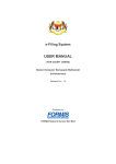
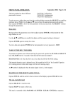
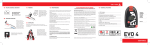
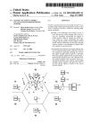
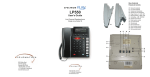
IMSI/IMEI Catcher NS-17-3G User Manual NeoSoft 2012 All rights reserved 2 CONTENTS 1 Introduction 3 2 System overview 4 3 Operational overview 5 4 What is in the package for Catcher 850/1900 MHz? 6 5 Controls description 6 Main software “3G BTSXXX” page 7 Technical Specifications Appendix 1 © 8 10 12 13 14 All rights reserved 3 1 Introduction This document provides the product description, technical characteristics and maintenance recommendations of the 3G IMSI/IMEI catcher (NS-17-2). The basic features of NS-17-2 3G catcher are: Operation in 850, 900, 1700, 1900, 2100 3G bands; Automatically scanning and detecting parameters of all 3G networks; Detecting 3G phones and collecting their IMSI/IMEI identities in real time; Displaying phone model and name of network Provider; Measuring distance to all 3G phones with accuracy of less than 30 m; Jamming 3G selected networks in the working area; Forcing handsets to migrate to GSM mode. It makes possible interception of such phones by GSM semi/active and passive interception systems. All software operations described in this document must be performed by organizations and companies only in accordance with national and international Laws. All rights reserved 4 2 System overview Our specialized 3G IMSI/IMEI catcher NS-17-2 is intended for governmental agencies and law enforcement groups in order to collect basic GSM information (IMSI, IMEI) about handsets in the local area (airport terminals, prisons etc). By using our special GSM Base unit it is possible to create a special micro system that can detect presence of the group of handsets in the place of interest. In general, the NS-17-2 catcher comprises the following key components: Compact 3G Base unit with Antenna set and gateway Portable computer; Notebook computer with software. Functional diagram of the 3G IMSI/IMEI Catcher with downgrading handset to GSM monitoring system is represented below: BTS 1 (3G Provider) Twister software IMSI IMEI 3G IMSI/IMEI Catcher Active Stations RX TX Target GSM BTS unit A5.1 deciphering unit 5 3 Operational overview The Compact 3G Base unit provides a very attractive channel in its operational area. After this chanel has beeen detected by mobile phones, located within system’s operational area, they send a reqistration request (since there is no difference for mobile phones either to register in a network created by us or in one of a real external network). This system uses special sophisticated algorithms therefore not only those 3G phones which are located very close to the BTS but those which are relatively far away from the NS-17-2 will register in this micro network. The system operates secretly, so that the mobile station subscriber is unable to detect it. The system does not interfere with the external mobile 3G networks. The system ensures selection of subscribers (targets) according to known IMSI or/and IMEI identifications. Also, it has the means of detection of such identifications according to the results of statistical processing of a list of registered subscribers. There are two main modes of operation for Twister 3G IMSI/IMEI catchers: «IMSI/IMEI catcher» mode Once the compact 3G Base Unit of NS-17-2 requests mobile phones to introduce themselves, i.e. to send their identities – IMSI and IMEI. This mode is intrinsic to the system and a part of all other modes. The Software of the system initiates operation of base station. A cell is created (further – internal network) where the MCC, MNC, frequency and SC correspond to the parameters of one of the real cellular network operators that operates in this area (further – external network), the LAC differs from the same used in real network. Mobile phones located within its operational area (further - subscribers) will detect activation of a attractive channel and start registration procedure. They provide the system with their IMSI/IMEI identities (received in real 3G network). In the “HLR control” program window there appears a list of registered subscribers. For the subscribers there is no difference between registration in this micro internal network or the real external network. After registration procedure each subscriber can goes to the external network or may be blocked (according with the operators task). For NS17-2 unit it is possible also to show for a subsriber that there are no 3G BTS in the neighboirhood. That’s why all 3G handsets goes to 2G band BTS after registering procedure. «Targets correlation» mode 6 This mode allows the system to search of identifications of subscribers of interest according to information (IMSI, IMEI and their combinations) accumulated during operation of the system. Some of the additional applications for NS-17-2 are: Presence verification; Data Analysis; Direction Finding Support (in combination with 2G monitoring systems). NS-17-2 can be used either as a stand-alone device or integrated with GSM monitoring systems. In the last case the main GSM monitoring program will arrange operation of 3G modules. 4 What is in the package for Catcher 850/1900 MHz? Thank you, for choosing our 3G IMSI/IMEI Catcher system. All system units that listed above can be assembled in one tower and can be packed in a specially prepared Pelican Case 1660 model. Computer with the specialized software. It is not included if 3G Cather operates with GSM monitoring system 3G IMSI/IMEI catcher unit 850 band 3G IMSI/IMEI catcher unit 1900 band 7 Power supplier 90-264 AC/24DC Power supplier 9-36DC/24DC Diplexers for 850/1900 MHz bands Directional antennas Cables Omnidirectional magnetic aerials User’s Manuals Pelican Case 1660 model 8 5 Controls description The front panel for 3G IMSI/IMEI Catcher contains the following controls: Power button with led indicator, Product Name “Twister” and band label. Product name LED Indicator Power Button When Led indicator “Power” is red, then unit is powered. The unit is ready for operation after 3 min after switching ON. Power 24V Output air RX plug LAN HUB TX plug UNIT ID Input air The back side of the unit contains the following controls: Power 24V plug, Input (RX) antenna plug, Output (TX) antenna plug, 3 LAN plugs, Label with unit ID code. 9 Power 24V plug must be connected to Power supplier 90-264 AC/24DC or Power supplier 9-36DC/24DC via 3 pin power cable. This cable have logic polarity. There is no way to connect it incorrectly. Each LAN plug is equal capabilities. You can connect network device to each of them. In order to provide normal temperature inside unit a special air circulation is performed. Cold air comes from “Input air” part of the unit and hot air goes out from the “Output air” hole. Normal temperature inside unit is up ◦ ◦ to 50 C. After 50 C the device protection scheme will switch Off 3G BTS. But network ID device inside unit will stay connected and operator can remotely check disconnecting cause and a temperature inside block. When temperature inside unit will come to normal value it will be possible to switch unit ON again after restarting Twister main program. By the default, 3G Catcher unit must be connected to 2 antennas (RX and TX). For 850/1900 bands operation it is required 2 separate 3G Catcher units. In order to decrease quantity of antennas the system includes two 850/1900 diplexers (2 antennas instead of 4). RX plug from each unit must be connected to one diplexer, and TX plug from each unit must be connected to another diplexer. It is very important to connect plugs meeting the condition of bands. 1900 MHz 850 MHz To RX 850/1900 antenna To TX 850/1900 antenna 10 As for directional RX and TX antennas they must be separated by each other as maximum as it is possible (1-3m). If operator use omnidirectional antennas then they must be separated vertically (for example: one - on the roof of the car, another inside saloon-car). 6 Main software The 3G IMSI/IMEI Catcher can be monitored by separate PC, or by main computer from a GSM monitoring system. In both cases the main software can recognize network devices and create visual indication of the current system configuration. The program interface of the 3G IMSI/IMEI Catcher system, integrated in GSM monitoring system, is listed below 7 11 6 1 2 4 3 5 15 8 9 11 10 14 13 1 2 3 4 5 6 7 8 – – – – – – – – Indicator of normal operation of the internal network BTSx unit; Indicator of normal operation of the internal network ASx unit; Indicator of normal operation of the 52 support; Indicator of normal operation of the 51 support; Operating time of the system; Registered subscriber list window - «HLR control»; «Cell/Target list» window; Window of active stations - «Active stations»; 11 9 – Paging channel station (it is located in window of the active stations since all of them are located in the same module); 10 – Window - «Receivers» indicates channel number and network identification that the BTS is tuned to; 11 – Protocol window - «Protocol»; 12 – Main control panel for GM program; 13 – 3G IMSI/IMEI catcher unit 850MHz 14 – 3G IMSI/IMEI catcher unit 1900MHz 15 – BTS settings button All main controls for GSM monitoring system are described in the corresponding description. When visual indicators of 3G IMSI/IMEI catcher units 13, 14 appears then you may start work with them. The state of the unit must be “Switched off”. If there is another message in state then switch off this unit using corresponding button in the right side of the main control panel 12. Before any setup of a 3G IMSI/IMEI catcher unit you must activate scanning mode. It is also required when the system is located in the new place. If the system is installed in a vehicle then vehicle must stop. Right button click above the required unit and select Scanning -> Quick. The message “Switched off” in State must be changed to “Scanning on band XX”. XX means band number according the 3G standard. For example: band 2 means 1900MHz, band 5 means 850 MHz. Visually this mode may be controlled when message “Scanning …” appears in window of 3G BTS that makes scanning routine. Scanning mode stops on its own. Average duration of this mode is 3-5 minutes. During scanning some detail information will appear in the State field. The system determines the cellular 3G network providers available within system’s operational area and makes preparations to be more attractive for 3G handsets among them. If scanning procedure finished successfully then in State will appear message “Finish BCH scan on selected PLMN”. In case of “Error” message in State try to rescan. If no success and “Error” message appears again then close main program, switch off current 3G BTS unit from the front panel. Then switch on it again. Start main program and repeat scanning procedure. When scanning procedure is finished successfully, then you must push button 15. A special “Settings” window will appear. Click on a tab which name stars by “3G…”. Let’s consider 3G BTS setup. 12 “3G BTSXXX” page This 3G BTS setup is possible only when scanning procedure is finished successfully. There are several operational modes of a 3G BTS: 3G IMSI/IMEI catcher mode; Block Carrier mode. In 3G “IMSI/IMEI catcher” mode the program collect IMSI/IMEI identities from 3G handsets that stay in the working area. If a target is pointed in the “Target window” then its name will be automatically added to a row with the corresponding identity. Also, it is possible to save a list of identities that appears in the working area. In the “Block Carrier” mode 3G BTS tell handsets that no 3G network here and the possible way of communication is to operate in GSM band. Only one of the pointed modes can be selected in one time. Operator must select the required 3G provider from MCC-MNC drop down list. Do not place MCC-MNC code for providers not presented in the MCC-MNC drop down list. Also operator must select operational mode according with the required task and setup output power level. Then set a tick TX power. Push “Apply” button and repeat settings for another 3G BTS unit. Then push “OK” button. Message “IMSI catcher started” will appear on the corresponding 3G receiver. In the “HLR Control” window will appear 3G subscribers. In order to activate “Block Carrier” mode set tick “Block Carrier” and repeat all settings with MCCMNC and power that were described for “IMSI/IMEI catcher” mode. At maximum power 3G BTS activity in this mode can be around 200 meters. 3G handsets loose 3G network and try find to the best BTS signal in GSM mode. This algorithm of operation is acceptable if handset support both 3G and GSM mode. service. If handset is tuned for operation in 3G only mode then it will be out of communication 13 7 Technical Specifications Each unit in the 3G IMSI/IMEI Catcher system is a separate network device and can be located in different places. Unit’s connection in this case can be organized by Virtual Private network (VPN), using Internet high encrypted tunnel channel. Each unit steady for vibration and can be installed in a vehicle. GSM Range Power Output power Operation Range Dimensions Connection with PC and other units UMTS 850, 900, 1700, 1900, 2100 MHz 90-264 AC/24DC , 9-36DC/24DC 0.2 -5 Watts in 5MHz 50..300 m 330x268x80 mm LAN, Internet via VPN One unit can be tuned to separate bands, but bands 1700MHz and 2100 MHz are not compatible. In multiband case 3G Catcher stay some time on one band, then switch to another etc. In this operation there is a probability of loosing a target, when it comes in time of operation on another band. That’s why our recommendation is to use one 3G Catcher unit for one corresponding band. 14 Appendix 1 «Target correlator» utility Introduction In practice one can reach a situation where it is necessary to separate a group of subscribers and monitor only their communications. Other subscribers are considered to be uninteresting and they can be asked to move back into the external network. The Internal network must be forbidden for them. This is called “IMSI/IMEI selection” in the GM program. The main problem is how to find the initial IMSI and/or IMEI data for the target selection process. This utility is aimed to evaluate these parameters using a special correlation method. The main idea of this method is the comparison of the data lists for the registered subscribers. Each list is the result of the GM system operation in “Catcher” mode in different times and locations. Usually the internal network is created in areas with the highest probability of the target’s appearance (near office, home, exhibitions etc). Thus, after correlation analysis, the operator can identify the IMSI and/or IMEI identities that appear many times in these locations. These identities can be considered as potential targets and will be setup in the GM program as targets. Utilizing this utility can increase efficiency of the GM system operation in selection mode. Program interface The main window consists of two parts (Fig.A.3.1) In the left part is the “HLR files list” the operator can open a group of files created by the GM program in the “IMSI/IMEI catcher” mode. Each file is a copy of the “HLR Control” list (made by the GM system) with subscribers, registered in some saved area description. 15 1 2 3 14 19 4 5 6 7 15 8 9 16 20 10 11 12 2 17 13 18 21 22 26 23 24 25 27 Fig.A.4.1 “Target correlator” main window In the right part the “Results” will be placed in the results of correlation analysis according to the operator’s request. Buttons in the main control panel and main menu items are intended to carry out file control functions and correlation algorithms settings. Lets consider the main panel controls (Fig.A.4.1) 1. Button «Open HLR file» is intended for opening one file, created by GM software in “IMSI/IMEI catcher” mode. The file header contains the following information, separated by “_” chars: BTS location name (The GM system operator creates this name in the GM software); Target presence flag (According to the GM operator. This flag is switched ON by “TP” checker in the GM software); GSM provider MCC-MNC number; Current file number in the folder (the number is increased by saving “HLR Control” list in GM software); For example file «test3_1_99008_01» must be decoded as follows: The system was located in the so called “test3” place. Target at the moment for “HLR Control” list saving was present in the internal network. Internal network BTS was tuned to one of the ARFCN channels for GSM provider 990-08. This is the first “HLR Control” list copy that was held in this place. 2. Button «Open HLR group file» is intended for opening a group of HLR files that were united by operator during one of the previous sessions for target localization with the help of the “Target Correlator” utility. “HLR files list” will be completely updated. If it is necessary to add a new file to the current workgroup of the HLR files just push button 1 and select the requested file name. 3. Button «Save selected HLR files as a single group» is intended to save selected files in the “HLR files list” as a new workgroup file. This workgroup may be opened in future with the help of the button 2. 4. Button «Set request state “Target is present in selected files”» is intended to setup the flag that target is present in the selected files (see methodic for target localization). 16 5. Button «Set request state “Target is not present in selected files”» is intended to setup the flag that target is not present in the selected files (see methodic for target localization). 6. Button « Disable all request states for selected rows» is intended to mark selected files as not informative during correlation analysis (see methodic for target localization). 7. Button « Disable all request states for all rows» is intended to mark all open files as not informative during correlation analysis (see methodic for target localization). 8. Button «Delete selected HLR files» is intended to delete selected rows from the «HLR files list». This action will not delete selected files from HDD. Actions 4-8 may be achieved from the popup menu below “HLR files list” for selected records. 9. Button «Search targets with same IMSI» is intended to detect the same “IMSI” identity in the opened files. 10. Button «Search targets with same IMEI» is intended to detect the same “IMEI” identity in the opened files. For “Target Correlator” normal operation one of buttons 9 –10 must be pushed (or both of them). 11. Button «Start correlation analysis» is intended to start correlation analysis algorithm. 12. Button «Parameters» is intended to setup color and font styles for correlation results. Also at this page there is a field to setup minimal quantity of coincidences to be accepted as good result for identity localization. 13. Button «Find data in target correlator list» is intended to find pointed identity in the “Results” list. A special window appears. In this window there is a possibility to setup required identity type (IMSI or IMEI) and point identity value. It is accepted 15 hex digit value or combination “*”and a group of hex digits. The char “*” can be used instead of group any hex digits. 14. Field «Req state» is intended to show that target is present in the current file according with operator’s opinion. This flag may be changed by operator with the help of buttons 4-7 in “Target correlator”. If this field is empty (not contain “+” or “-” char) then this file is not accepted for correlation analysis. 15. Field «User state» is intended to show that target is present in the current file according with GM system operator’s opinion. This flag may be changed only in GM software after pushing “TP” button for “HLR Control” list. 17 16. Field «File Name» is intended to show name of investigated file. 17. Field «Created» is intended to show creation date and time for investigated file. 18. Field «Size» is intended to show size of investigated file. Information in fields 15 and 16-19 is read only and couldn’t be modified by operator. Information in field 14 may be changed according with the correlation methodic after row selection with the help of buttons 4-8 or popup menu. 19. Label «Files count» is intended to show the quantity of selected files in “HLR files list”. 20. Label «Group Name» is intended to show name of a group of HLR files that were united by operator during one of the previous sessions for target localization with the help of “Target Correlator” utility and saved as workgroup. Useful to workgroup opened by pushing button “2”. 21. Button «Delete selected rows» is intended to delete selected rows from the “Results” list. 22. Field «Target» is intended to show the target’s name if it is possible to find it from one of the files after correlation analysis. 23. Field «IMSI» is intended to show the target’s IMSI identity after correlation analysis. 24. Field «IMEI» is intended to show the target’s IMEI identity after correlation analysis. 25. Field «RXlev» is intended to show the power signal level for the target’s handset. This value can be accepted as indirect evidence for distance to the target and signal quality in the working place. If the operator will click on this field then a list of GM system locations where this identity was present will appear. The quantity of locations is dependent on a combination of selected files quantity and containing the field “14”. Fields 22-25 are read only. 26. Label «Records Whole» is intended to show the whole quantity of records in “Results” list. 26. Label «Records Find» is intended to show the quantity of records where some identity appears more than “Minimum of coincidences” times (equal also accepted) – see “Parameters” window description. Some of main functions are duplicated by “Hot buttons”. You can see them in the main menu. 18 Target identification by IMSI/IMEI This method is based on correlation analysis where some identity appears in the different places at different times. The Operator can setup different conditions for file analysis. At any time results will be the different from each other according to the local operator’s tasks and surmises. The main logic is based on coincidence for some identity in the different files checked by operator as “+” in “14” field in the “HLR files list”. If the operator puts char “-” in 14 field then all identities from this file must be deleted from the result. If Field 14 is empty then all identities from this file do not take part in the analysis. The most common steps for target correlation must be as follows: Push button “1” and in dialog windows “Open” select requested files with extension “*.hlr”. You can select a several files in one time. All files are located in the folder “C:\Program Files\GM\ HlrState”. Push “Open” button. All files will be listed in “HLR files list” (Fig.A.4.1). Files internal data can be represented in the table Tab.A.4.1. At this moment this information is unreachable for operator. Task The main idea is as follows: Some target used a SIM card from 990-08 provider; It was registered by the GM system on several occasions because each file contains the same IMSI “222222222222222”; In two different places the target used the same handset (IMEI 35708400331214). Then, the SIM card was inserted into another handset (IMEI 35708400331251). In the working place “test1” the operator made a mistake and supposed that target was not registered in the “HLR Control” window. He pushes button “TP” without presence flag. In the file name this action is marked as (_0_). Then he worked in place “test2” and stays here for a long time. He found the target and had visual contact with him. But at this moment he couldn’t find the target’s identity in the “HLR Control” list and just saves list of registered subscribers with a flag that target is present here. 19 The same situation was held in place “test3”. Target Name “test” is shown for imitation of the real situation. It is requested to find the target’s identity with the help of the “Target Correlator” utility. Tab.A.4.1 N Target Name 1 2 3 test IMSI IMEI RXlev File Name 222222222222222 35708400331214 -81/77 test1_0_99008_01.hlr 111111111111111 35504800775313 -85/85 333333333333333 35758300342563 -73/85 444444444444444 35834800775313 -77/44 222222222222222 35708400331214 -79/65 555555555555555 35548300342563 -93/82 777777777777777 35504805475313 -73/85 222222222222222 35708400331251 -72/58 888888888888888 35723300342563 -93/82 test2_1_99008_01.hlr test3_1_99008_01.hlr Solution After using field “15” analysis, the operator finds a group of files where target was present in the “HLR Control” list. In our case there were “test2_1_99008_01.hlr” and “test3_1_99008_01.hlr”. The Operator must select this files and push button “4” (Fig. A.4.1) or “F5” or choose the popup menu «Set request state “Target is present in selected files”». In field “14” for selected records will appear char “+”. It means that correlation algorithm will process selected files and the operator supposes that target is present in both of them. The Operator must press button “9”. This mean that only the IMSI identity is interesting to the operator; The Operator must press button “11” or “F9” to run correlation analysis. In the list “Results” will appear for one target with identity IMSI “222222222222222”. If operator will setup flag that target is not present in the current file for “test1_0_99008_01.hlr” (in field “14” char “-” will appear) then all identities from 20 this file will be deleted from the result list and it will be empty. That’s why presence flag in the field “15” must be considered only as reference source because it may contain the GM operator’s error. “Parameters” window When the operator pushes button “12” a special “Parameters” window appears. It is intended to change the records parameters for the “Results” list in order to make them more informative. The Operator can make the following main settings: Change font Name, color and style for result record in special dialog box that appears after pushing “1” button in the “Parameters” window; Change background color for result record in special dialog box that appears after pushing “2” button in 2 “Parameters” window; 1 Setup minimum of identity 3 coincidences parameter (Field “3” in “Parameters” window). Correlation algorithm will show as a result only those identities which appears in processing files equal or more times than the allocated value. Settings preview is presented in the top part in “Parameters” window. “Ok” button is intended to save settings with closing “Parameters” window. “Apply” button is intended to save settings without closing “Parameters” window. “Cancel” button is intended to discard settings with closing “Parameters” window.