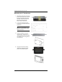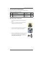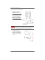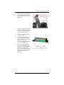
1
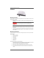
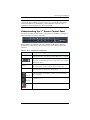
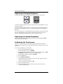
Bantam
Product
Name
Installation
Guide
Quick
Reference
Guide
Part No. 875-0265-000
Rev B1
Part No.
This device complies with part 15 of the FCC Rules. Operation is subject to the following two
conditions:
(1) This device may not cause harmful interference, and
(2) this device must accept any interference received, including interference that may cause
undesired operation.
Copyright Notice
Hemisphere GPS Precision GPS Applications
Copyright © Hemisphere GPS (2011). All rights reserved.
No part of this manual may be reproduced, transmitted, transcribed, stored in a retrieval system or
translated into any language or computer language, in any form or by any means, electronic,
mechanical, magnetic, optical, chemical, manual or otherwise, without the prior written
permission of Hemisphere GPS.
Trademarks
Hemisphere GPS®, the Hemisphere GPS logo, A100TM, A20TM, A21TM, A220TM, A221TM, A30TM,
A31TM, A42TM, A52TM, AerialACETM, AirStarTM, AirTracTM, AutoMateTM, BantamTM, BaseLineHDTM,
BaseLineXTM, BEELINE®, COASTTM, Contour LockTM, Crescent®, Earthworks®, EclipseTM, e-Dif®,
eDrive®, eDriveTCTM, eDriveVSiTM, eDriveXTM, FliteTracTM, G100TM, GateMateTM, GPSteerTM, H102TM,
HQTM, IntelliFlow®, IntelliGateTM, IntelliStarTM, IntelliTracTM, Just Let GoTM, L-DifTM, LiteStar IITM,
LV101TM, LX-1TM, LX-2TM, M3TM, MapStar®, MBX-4TM, miniEclipseTM, OutbackTM, Outback 360TM,
Outback Guidance CenterTM, Outback Guidance®, Outback HitchTM, Outback STM, Outback S2TM,
Outback S3TM, Outback S-LiteTM, Outback StsTM, Outback Steering GuideTM, PocketMAX PCTM,
PocketMAXTM, PocketMax3TM, R100TM, R131TM, R220TM, R320TM, Satloc®, the Satloc logo, SBX-4TM,
V101TM, V102TM, V111TM, VS101TM, VS111TM, VectorTM, X200TM, X300TM, XF100TM, XF101TM, and
XF102TM are proprietary trademarks of Hemisphere GPS. Other trademarks are the properties of
their respective owners.
Patents
The Outback STM and S-LiteTM automated navigation and steering guide systems are covered by
U.S. Patents No. 6,539,303 and No. 6,711,501. The Outback HitchTM automated hitch control system
is covered by U.S. Patent No. 6,631,916. The Outback eDriveTCTM GPS assisted steering system is
covered by U.S. Patent No. 7,142,956. Hemisphere GPS products may be covered by one or more
of the following U.S. Patents:
6,111,549
6,397,147
6,469,663
6,501,346
6,539,303
6,549,091
6,631,916
6,711,501
6,744,404
6,865,465
6,876,920
7,142,956
7,162,348
7,277,792
7,292,185
7,292,186
7,373,231
7,400,956
7,400,294
7,388,539
7,429,952
7,437,230
7,460,942
Other U.S. and foreign patents pending.
Notice to Customers
Contact your local dealer for technical assistance. To find the authorized dealer near you:
Hemisphere GPS
2207 Iowa Street
Hiawatha, KS 66434
Phone: 785-742-2976
Fax: 785-742-4584
[email protected]
www.hemispheregps.com
Technical Support
If you need to contact Hemisphere GPS Technical Support:
8444 N 90th St, Suite 130
Scottsdale, AZ 85258 USA
Phone: (480) 348-9919
Fax: (480) 348-6370
[email protected]
Documentation Feedback
Hemisphere GPS is committed to the quality and continuous improvement of our products and
services. We urge you to provide Hemisphere GPS with any feedback regarding this guide by
writing to the following email address: [email protected].
Contents
Chapter 1
Getting Started . . . . . . . . . . . . . . . . . . . . . . . . . . . . 1
Parts List . . . . . . . . . . . . . . . . . . . . . . . . . . . . . . . . . . . . . . . . . . . . . . . 2
Component Weights . . . . . . . . . . . . . . . . . . . . . . . . . . . . . . . . . . . . . 4
Planning the Installation . . . . . . . . . . . . . . . . . . . . . . . . . . . . . . . . . . 4
Chapter 2
Mounting the Components . . . . . . . . . . . . . . . . . . . 5
CPU . . . . . . . . . . . . . . . . . . . . . . . . . . . . . . . . . . . . . . . . . . . . . . . . . . . 6
Touchscreen . . . . . . . . . . . . . . . . . . . . . . . . . . . . . . . . . . . . . . . . . . . . 6
The 7” Touchscreen Mounting Kit . . . . . . . . . . . . . . . . . . . . . . 7
Mounting the 7" Touchscreen . . . . . . . . . . . . . . . . . . . . . . . . . . 8
The 8.4" Touchscreen Mounting Kit . . . . . . . . . . . . . . . . . . . . . 9
Mounting the 8.4" Touchscreen . . . . . . . . . . . . . . . . . . . . . . . . 9
Power Panel . . . . . . . . . . . . . . . . . . . . . . . . . . . . . . . . . . . . . . . . . . . 10
Power Panel Mounting Location . . . . . . . . . . . . . . . . . . . . . . 10
Mounting the Power Panel . . . . . . . . . . . . . . . . . . . . . . . . . . . 10
Lightbar . . . . . . . . . . . . . . . . . . . . . . . . . . . . . . . . . . . . . . . . . . . . . . . 11
Lightbar Mounting Location . . . . . . . . . . . . . . . . . . . . . . . . . . 11
The Lightbar Mounting Kit . . . . . . . . . . . . . . . . . . . . . . . . . . . 11
Mounting the Lightbar . . . . . . . . . . . . . . . . . . . . . . . . . . . . . . . 11
Antenna . . . . . . . . . . . . . . . . . . . . . . . . . . . . . . . . . . . . . . . . . . . . . . . 14
Mounting Location . . . . . . . . . . . . . . . . . . . . . . . . . . . . . . . . . . 14
Mounting the Antenna . . . . . . . . . . . . . . . . . . . . . . . . . . . . . . 14
Chapter 3
Connecting the CPU . . . . . . . . . . . . . . . . . . . . . . . 15
Warnings . . . . . . . . . . . . . . . . . . . . . . . . . . . . . . . . . . . . . . . . . . . . . . 16
General Cable Connection Warnings . . . . . . . . . . . . . . . . . . . 16
Antenna Cable Warning . . . . . . . . . . . . . . . . . . . . . . . . . . . . . 16
Connections Diagram . . . . . . . . . . . . . . . . . . . . . . . . . . . . . . . . . . . 17
Connecting Cables . . . . . . . . . . . . . . . . . . . . . . . . . . . . . . . . . . . . . . 17
Connecting the GPIO Cable . . . . . . . . . . . . . . . . . . . . . . . . . . . 18
Connecting the Lightbar Cable . . . . . . . . . . . . . . . . . . . . . . . . 18
Connecting the Antenna Cable . . . . . . . . . . . . . . . . . . . . . . . . 18
Connecting a Keyboard and/or Mouse . . . . . . . . . . . . . . . . . 18
Using the Flow Control Port . . . . . . . . . . . . . . . . . . . . . . . . . . 18
Connecting the Video (VGA) Cable . . . . . . . . . . . . . . . . . . . . 18
About the Power Cable . . . . . . . . . . . . . . . . . . . . . . . . . . . . . . 19
Connecting the Power Cable . . . . . . . . . . . . . . . . . . . . . . . . . . 19
Connecting the USB Extension Cable . . . . . . . . . . . . . . . . . . 20
Chapter 4
Operating Bantam . . . . . . . . . . . . . . . . . . . . . . . . 21
Bantam Installation Guide
iii
PN 875-0265-000 Rev B1
Contents
Powering the System . . . . . . . . . . . . . . . . . . . . . . . . . . . . . . . . . . . . 22
Turning the CPU and Screens On . . . . . . . . . . . . . . . . . . . . . . 22
Inserting and Removing the USB Flash Drive . . . . . . . . . . . . . . . . 22
Understanding the 7” Screen Control Panel . . . . . . . . . . . . . . . . . 23
Adjusting the Display Brightness . . . . . . . . . . . . . . . . . . . . . . . . . . 24
Adjusting the Lightbar Brightness . . . . . . . . . . . . . . . . . . . . . . . . . 24
Calibrating the Touchscreen . . . . . . . . . . . . . . . . . . . . . . . . . . . . . . 24
Turning the System Off . . . . . . . . . . . . . . . . . . . . . . . . . . . . . . . . . . 25
Index . . . . . . . . . . . . . . . . . . . . . . . . . . . . . . . . . . . . . . . . . . . . . . . 27
End User License Agreement . . . . . . . . . . . . . . . . . . . . . . . . . . . . 29
Warranty Notice . . . . . . . . . . . . . . . . . . . . . . . . . . . . . . . . . . . . . . 32
Bantam Installation Guide
iv
PN 875-0265-000 Rev B1
Chapter 1: Getting Started
Parts List
Component Weights
Planning the Installation
Bantam Installation Guide
1
PN 875-0265-000 Rev B1
Chapter 1: Getting Started
T
he Bantam is a modular system that features a powerful CPU in a rugged
aluminum box. The CPU contains a serial port for each module. Each module of
the system connects to the CPU via a specific cable.
The system modules that ship with the Bantam and connect to the CPU are:
•
7”or 8.4” color touchscreen
•
Lightbar
•
Antenna
•
Optional switches (spray on/off, swath advance)
Read this entire manual before beginning installation. Failure to
follow the instructions in this manual could void your warranty.
Pay careful attention to safety reminders and warnings to eliminate the possibility of
personal injury or damage to the system. Comply with all electrical connections and
requirements to prevent damage to the system.
Parts List
Review the contents of your Bantam purchase to ensure the components are not
damaged. The contents will vary depending on whether you ordered a 7” or 8.4”
screen.
Table 1-1: Bantam main parts list
Component
Part Number
Qty
Bantam switches and kits. See Table 1-2.
880-1031-000
Bantam cables. See Table 1-3.
880-1030-000
Bantam CPU
806-1062-000#
1
Bantam Installation Guide (this manual)
875-0265-000
1
AirTrac User Guide
875-0105-001
1
AirTrac Quick Reference Guide
875-0136-001
1
A21 L-Band antenna (with mounting template)
804-3036-000#
Color touchscreen - 7”
380-0016-000#
1
Color touchscreen - 8.4”
806-3015-000
1
Lightbar - V1
806-2011-03A
1
Lightbar cable
051-0022-001
1
Antenna cable
052-0005-000#
1
or
Bantam Installation Guide
2
PN 875-0265-000 Rev B1
Chapter 1: Getting Started
Table 1-2: Bantam parts list - switches and kits
Component
Part Number
Qty
Warranty statement
875-0066-001
1
Push switch (for use with GPIO cable 051-0244-000#, see
Table 1-3). This is the optional swath advance switch.
075-4002-000
1
Lever switch (for use with GPIO cable 051-0244-000#, see
Table 1-3). This is the spray on/off switch.
075-4001-000#
1
Lightbar mounting kit. See “The Lightbar Mounting Kit”
on page 11.
710-0029-002
1
MapStar kit (CD and MapStar User Guide)
710-0021-007
1
USB kit (extension cable, USB connector, USB flash
drive). See “Inserting and Removing the USB Flash
Drive” on page 22.
710-0087-000
1
Mounting kit - 7” touchscreen (mounting plates with
mounting template). See “Mounting the 7" Touchscreen”
on page 8.
710-0096-000#
1
Mounting kit - 8.4” touchscreen (ball sockets and arm
mount). See “Mounting the 8.4" Touchscreen” on page 9.
604-0013-000#
1
2GB USB flash drive (spare)
750-1083-000
1
Component
Part Number
Qty
Lightbar cable (CPU to lightbar)
051-0022-001
1
Video cable (CPU to touchscreen)
051-0243-000#
1
GPIO cable (CPU to optional spray on/off switch, optional
swath advance switch, serial [DB9] connector)
051-0244-000#
1
Antenna cable
052-0005-000#
1
Power cable assembly.
726-1096-000#
1
or
Table 1-3: Bantam parts list - cables
(Includes mountable panel with power switch [for the
CPU], circuit breaker and dimmer switch to control the
lightbar brightness.)
Bantam Installation Guide
3
PN 875-0265-000 Rev B1
Chapter 1: Getting Started
Component Weights
Table 1-4: Component weights
Component
Weight
CPU
8.58 pounds (3.89 kg)
Touchscreen - 7”
1.35 pounds (0.61 kg)
Touchscreen - 8.4”
4.46 pounds (2.02 kg)
Lightbar V1
4.2 pounds (1.91 kg)
Complete cable set
7.0 pounds (3.18 kg)
Antenna
0.75 pounds (0.34 kg)
Planning the Installation
Before beginning the installation, plan it by considering:
•
Cable lengths
•
Clearance space
•
Power source
•
Vehicle structure
•
Visibility
•
Balance (air installations)
In planning your installation locations, see Chapter 3, “Connecting the CPU” for a
visual overview of how the components are connected.
Bantam Installation Guide
4
PN 875-0265-000 Rev B1
Chapter 2: Mounting the Components
CPU
Touchscreen
Power Panel
Lightbar
Antenna
Bantam Installation Guide
5
PN 875-0265-000 Rev B1
Chapter 2: Mounting the Components
B
efore installing any components, read the short section “Planning the
Installation” on page 4.
Review all warnings in Chapter 3, “Connecting the CPU” before
attempting to connect any of the components together using the supplied cables.
Connecting cables improperly can damage your system.
Consider using existing hardware and hardware locations. Avoid
drilling holes that may damage other equipment (such as structural frame members,
electrical cables, or fluid lines).
Where hardware, such as screws, washer and nuts, is not provided for a particular
mounting or installation, you will need to provide the hardware appropriate to your
particular needs.
CPU
The CPU is a semi-permanent fixture once installed—there is no quick release
mechanism.
Install the CPU in any location inside the vehicle that has the necessary room and is
sheltered from the elements, for example in a storage compartment, in the cab,
behind the seat. The CPU must have sufficient clearance to be accessible for attaching/
removing cables (front and both sides) and for inserting and removing the USB flash
drive (however, see “Inserting and Removing the USB Flash Drive” on page 22).
Obtain the necessary hardware to secure the CPU through its fitting points at each
corner and install it in your selected location.
Do not mount the CPU vertically. The CPU must be mounted on a
horizontal surface.
Touchscreen
Mount the touchscreen inside the cockpit or cab of the vehicle where it is:
•
Easily visible while flying or driving
•
Within arm’s reach
Do not obstruct the view or access to other instruments or the flying or
driving visibility of the pilot or driver.
Bantam Installation Guide
6
PN 875-0265-000 Rev B1
Chapter 2: Mounting the Components
The 7” Touchscreen Mounting Kit
Note: You will need to be able to get behind the dashboard to secure the dash
mounting plate.
The 7”touchscreen comes with a template, mounting plates and mounting hardware
as follows:
Table 2-1: 7” touchscreen mounting kit
Item
Description/usage
Part Number
Qty
1
Touchscreen mounting plate. Mounts on the
touchscreen for mounting on the dashboard
plate (item 5).
601-1203-000#
1
2
Screws, flat head M2.5 x 8 mm - secure plate
to back of touchscreen.
675-1207-000#
4
3
Screws, flat head M2.5 x 5 mm - secure plate
to base of touchscreen.
675-1137-000#
2
4
Template for the dashboard mounting plate.
Cut out and stick on the dashboard, drill as
indicated.
N/A
1
5
Dashboard (threaded) mounting plate.
Mounts on dashboard. Touchscreen
mounting plate attaches to this plate.
601-120000#
1
6
Screw, washer and nut. Attach dashboard
plate to dash.
675-1208-000# (screw)
4
678-10990000000
(washer)
4
7
Threaded knobs (also known as ‘flowerette
thumb screws’). Attach touchscreen and plate
assembly to dashboard plate.
Bantam Installation Guide
7
676-1066-000# (nut)
4
679-1011-000#
2
PN 875-0265-000 Rev B1
Chapter 2: Mounting the Components
Mounting the 7" Touchscreen
1.
Attach the touchscreen mounting
plate to the touchscreen. Use the
four 8 mm (length) screws into
the back of the touchscreen, the
two 5 mm screws into the
bottom of the touchscreen.
2.
Cut out the supplied template
and place it on a clear area of the
dashboard.
Note: You must be able to get
behind the dashboard to attach
washers and nuts.
3.
Drill the dashboard using the
template then, using the four
screws, washers and nuts, attach
the dashboard mounting plate to
the dashboard.
4.
Using the two thumb screws,
attach the touchscreen and its
plate to the dashboard plate.
Bantam Installation Guide
8
PN 875-0265-000 Rev B1
Chapter 2: Mounting the Components
The 8.4" Touchscreen Mounting Kit
The 8.4" touchscreen comes with a ball mount assembly as follows:
Table 2-2: 8.4" touchscreen mounting kit
Item
Description/Usage
Part number
Qty
1
RAM mount assembly, 10IU
603-1004-000#
1
2
Nut, 8-32 hex self-locking SS
676-1018-000#
4
Washer, flat, #8
678-1010-000
4
Mounting the 8.4" Touchscreen
1.
Identify the best available location for the ball and arm
mount.
2.
Using your own hardware, attach one ball mount to a
suitable structure/surface on the vehicle.
3.
Using the provided nuts and washers, mount the other
ball on the studs on the back of the touchscreen.
4.
With the arm installed between the two ball mounts, set
the touchscreen in a suitable position then tighten the
handle. (When loosening the handle, the socket on the
sprung side of the arm opens first.)
Bantam Installation Guide
9
PN 875-0265-000 Rev B1
Chapter 2: Mounting the Components
Power Panel
Power Panel Mounting Location
Mount the power panel—part of cable harness part number 726-1096-000#—inside the
cockpit or cab of the vehicle. The power panel must be within arm’s reach.
Do not obstruct the view or access to other instruments or the flying or
driving visibility of the pilot or driver.
Mounting the Power Panel
1.
Find an appropriate location in your cockpit or cab to mount the power
panel. It must be within easy reach of the pilot or driver.
2.
Depending on the selected location and vehicle type, use the appropriate
hardware (not supplied) to attach the power panel to the vehicle.
Bantam Installation Guide
10
PN 875-0265-000 Rev B1
Chapter 2: Mounting the Components
Lightbar
The lightbar installation is the same for aircraft and ground vehicles.
Lightbar Mounting Location
Mount the lightbar in front of the cockpit or cab at a comfortable viewing distance. You
can mount the lightbar either inside or outside of the cockpit or cab.
Do not block the view of the pilot or driver.
The Lightbar Mounting Kit
The lightbar mounting kit—part number 710-0029-002—contains these items:
Table 2-3: Lightbar mounting kit
Item
Description/usage
Part number
Qty
1
Flat panel plate
603-1005-000 (right side)
603-1006-000 (left side)
2
2
Screw, #8-32 (attach item 1 plate to
lightbar)
675-1100-000
2
3
Bracket – 1”
602-1007-000
4
4
Bracket – 3”
602-1008-001
2
5
Backing plate (use with item 8 if
required)
601-1045-000
2
6
#10-32 x 5/8” bolt, nut, and washer set
(bolt two x item 3s together, or an item 3
and an item 4 together).
675-1083-000 (bolt)
678-1038-000 (washer)
676-1016-000 (nut)
6
6
6
7
#10-32 x 1/2”bolt, washer and nut set
(bolt item 1 plates to item 3 or 4
brackets)
675-1086-000 (bolt)
678-1038-000 (washer)
676-1016-000 (nut)
4
4
4
8
#10-32 x 1¾” (and ¾” - optional) bolt,
washer and nut set (bolt item 3 or 4
bracket to vehicle - use item 5 backing
plates if necessary)
675-1085-000 (1¾” bolt)
675-1084-000 (¾ bolt)
678-1038-000 (washer)
676-1016-000 (nut)
4
4
4
4
Mounting the Lightbar
Tools Needed
•
Phillips screwdriver
•
3/16” Allen wrench
•
3/8” wrench
•
Electric drill
•
1/4” drill bit
•
Marker pen
Bantam Installation Guide
11
PN 875-0265-000 Rev B1
Chapter 2: Mounting the Components
Follow this procedure to mount the lightbar.
1.
Secure the left and right flat
panel plates to the lightbar using
the two #8-32 screws.
Note: The screw holes are offset
to the outside edge of the plate.
Also, the front of the lightbar
faces the thin edge of the plate
and the rear of the lightbar rests
on the thick edge of the plate.
Front of lightbar towards the thin edge of
the sloped plates.
If you have the left and right plates reversed it is still possible to line
up the plates so the arrows are pointing “outside.” However, the screw holes on the
lightbar and the flat panel plate will not line up if you have them reversed.
2.
Assemble the two sets of
1” brackets* using the #10-32 x
5/8” bolt, nut, and washer sets.
*Substitute a 3” bracket for one
of the 1” brackets if added height
is needed.
Bantam Installation Guide
12
PN 875-0265-000 Rev B1
Chapter 2: Mounting the Components
3.
Attach the left and right brackets
to the lightbar plates using the
four #10-32 x 1/2” screw, nut, and
washer sets.
4.
Using the assembled lightbar and
brackets as a template, mark the
four mounting hole locations on
the surface of the vehicle.
5.
Using a 1/4” drill bit, carefully
drill the four holes.
6.
Using #10-32 bolts, washers, and
nuts secure the lightbar to the
vehicle. Use the 1¾” or ¾” bolts
depending on if you are
mounting the lightbar on a thick
or a thin mounting surface
7.
If required, attach the backing
plates to the underside of the
mounting surface for additional
reinforcement. The backing
plates provide additional support
to prevent the bolts from pulling
through the surface under
vibration.
Bantam Installation Guide
13
PN 875-0265-000 Rev B1
Chapter 2: Mounting the Components
Antenna
Mounting Location
Antenna position is critical to system performance. These conditions must be met for
proper system operation:
•
Mount the antenna at least 5 ft (1.524 m) from transmitting antennas of any
frequency.
Positioning the antenna less than 5 ft (1.524 m) from
transmitting antennas of any frequency may cause overloading of RF
circuits.
•
Mount the antenna at the highest practical point that will give a good view of
the horizon.
•
The positions that the receiver calculates are at the positions of the antenna.
So, if using a swath guidance system, mount the antenna on the center line
of the vehicle
Mounting the Antenna
Hemisphere GPS recommends flush mounting the antenna to the roof of the vehicle.
Tools needed
•
Phillips screwdriver
•
Four #8-32 screws
•
Electric drill
•
1/8” drill bit
•
7/16” drill bit
•
Marker pen
Follow this procedure to mount the antenna.
1.
Use the A21 antenna mounting template to mark the mounting and antenna
connector hole locations on the outer surface of the vehicle.
2.
Using a 1/8” drill bit, carefully drill the four screw holes.
3.
Using a 7/16” drill bit, carefully drill the hole for the antenna connector.
4.
Use four #8-32 thread screws to secure the antenna to the surface of the
vehicle.
Bantam Installation Guide
14
PN 875-0265-000 Rev B1
Chapter 3: Connecting the CPU
Warnings
Connections Diagram
Connecting Cables
Bantam Installation Guide
15
PN 875-0265-000 Rev B1
Chapter 3: Connecting the CPU
Warnings
Heed all warnings before continuing. Failure to do so could void your warranty.
General Cable Connection Warnings
•
Turn off power before connecting or disconnecting cables. Failing to do so
can damage the system.
•
Finger-tighten all cable connections. Do not use any tools.
•
Do not route cables alongside power generator wire and other high-noise
electric sources. This will cause interference.
•
Do not kink or force cables into sharp bands. This can damage the cable.
•
Store excess cable length with at least a 6-in bend radius.
•
Do not coil the cables. This will introduce noise in the system.
•
Avoid high-temperature exposure (for example exhaust, manifold) when
routing cables.
Antenna Cable Warning
•
Never connect or disconnect the antenna cable with the power on.
•
Do not route the antenna cable with any other radio system cables. This will
cause interference. Keep 12 inches apart.
•
If you must cross the antenna cable with other cables, do so at a 90º angle.
This will prevent interference between systems.
Bantam Installation Guide
16
PN 875-0265-000 Rev B1
Chapter 3: Connecting the CPU
Connections Diagram
The following diagram provides a visual representation of the connections of the
Bantam system. Refer to this diagram when planning your installation, and again
when you are ready to connect the components.
USB extension cable, part of kit p/n 710-0087-000
(USB flash drive, connector, extension cable)
(to either port)
Antenna cable
p/n 052-0005-000#
(to antenna)
Flow control port - for
your flow control
system’s cable
Lightbar cable
p/n 051-0022-001
(to lightbar)
Power cable assembly
p/n 726-1096-000# (Power panel)
Video cable
p/n 051-0243-000#
(to touchscreen)
GPIO cable
p/n 051-0244-000#
(to spray on/off switch,
swath advance switch,
serial connector [DB9])
Connecting Cables
You install each Bantam cable between the CPU and a modular component, for
example the antenna cable or the touchscreen, or a peripheral device such as AgLaser.
Each cable is labeled with its name and part number and the connections are color
coded. Each cable can fit only one port on the CPU—it is impossible to connect a cable
to the wrong port.
Line up a connector with its matching pins and gently insert and turn.
Never force connections. Finger-tighten only (do not use tools).
Bantam Installation Guide
17
PN 875-0265-000 Rev B1
Chapter 3: Connecting the CPU
Connecting the GPIO Cable
The GPIO cable (part number 051-0244-000) comprises several individual cables: for
the spray on/off switch, the swath advance switch, a serial port (DB9) connector.
To connect the GPIO cable:
1.
Connect the Conxall connector end of the cable, part number 051-0244-000#,
to the CPU serial port labeled ‘GPIO’.
2.
Connect the spray on/off switch cable leads to the provided momentary lever
switch, part number 075-4001-000. Use the switch in conjunction with your
spray system on/off controls to synchronize actual spraying with the spray
data collection functionality of Bantam. See also “Using the Flow Control
Port” on page 18.
Do not connect spray on/off leads to a flow system if it
contains live voltage. Connection to a DC voltage will damage the circuit.
3.
(Optional) Connect the swath advance cable leads to push switch, part
number 075-4002-000, to control swath advances remotely.
Connecting the Lightbar Cable
1.
Connect the Conxall connector of the lightbar cable, part number 051-0022001, to the CPU port labeled ‘LIGHTBAR’.
2.
Connect the metal Bendix connector on the lightbar cable to the matching
connector on the back of the lightbar.
Connecting the Antenna Cable
Connect the antenna cable, part number 052-0005-000 between the socket on the left
side of the CPU and the A21 antenna.
Connecting a Keyboard and/or Mouse
You can connect a keyboard and a mouse that have USB connectors directly or
indirectly (through an extension cable) to the USB ports on either side of the CPU.
Using the Flow Control Port
Connect the cable that comes with your flow control system—IntelliFlow or
IntelliGate—to the flow control port.
Connecting the Video (VGA) Cable
1.
Connect the Conxall connector on cable part number 051-0243-000 to the
CPU serial port labeled ‘DISPLAY’.
2.
Connect the other end of the cable to the red-coded connector on the back of
the touchscreen.
Bantam Installation Guide
18
PN 875-0265-000 Rev B1
Chapter 3: Connecting the CPU
About the Power Cable
The power cable assembly—part number 726-1096-000—comprises the following:
•
Power panel on which there is an ON/OFF switch
•
Dimmer switch to control the lightbar’s brightness
•
Circuit breaker that prevents voltage spikes and reverse polarity from
damaging the system
Note: The ON/OFF switch powers the CPU and the touchscreens. It powers the 7"
touchscreen directly, the 8.4" touchscreen indirectly (see “Powering the System” on
page 22). The dimmer switch on the power panel controls lightbar brightness (both
touchscreens have their own display brightness controls).
Connecting the Power Cable
•
Do not connect to a power source of less than 10 volts.
•
Do not use a cigarette lighter as a permanent power source.
•
Do not reverse the polarity of the power leads—incorrect installation can
damage the system. Connect RED to POSITIVE (+) and BLACK to NEGATIVE
(-).
1.
Connect the Conxall connector to the CPU port labeled ‘POWER’.
2.
Connect the red and black power leads to a suitable power source that can
supply between 10 and 36 V (for example, vehicle battery, generator).
(Air Installation) A potential problem when installing an electronic
system in a vehicle is Counter Electromagnetic Force (CEMF). CEMF is caused when
relays or solenoids connected to the common vehicle DC power bus are de-energized.
The voltage produced may exceed 400 V. CEMF can be produced by equipment such
as:
•
Electric fan brakes
•
Air conditioners
•
Starter relays
•
Electric pump relays
To eliminate CEMF, install diodes at the relays and solenoids that cause the CEMF and
at the power supply cable connection of the SLX system. Use a 47 V, 5 W Zener Diode
(1N5368 or equivalent).
Bantam Installation Guide
19
PN 875-0265-000 Rev B1
Connecting the USB Extension Cable
To enable you to easily connect the USB flash drive to one of the CPU’s side USB
ports, kit part number 710-0087-000 includes an extension cable. Connect the
extension cable to either USB side port on the CPU then, using the connector
(adaptor), connect the USB flash drive to the extension cable. See also “Inserting and
Removing the USB Flash Drive” on page 22.
Note: You can use the other USB side port for a peripheral device such as a wireless
modem, tracking device, keyboard or mouse.
Chapter 4: Operating Bantam
Powering the System
Inserting and Removing the USB Flash Drive
Understanding the 7” Screen Control Panel
Adjusting the Display Brightness
Adjusting the Lightbar Brightness
Calibrating the Touchscreen
Turning the System Off
Bantam Installation Guide
21
PN 875-0265-000 Rev B1
Chapter 4: Operating Bantam
N
ow that the system is installed and connected, you are ready to turn it on and
use the USB, adjust the display and lightbar brightness, and calibrate your
touchscreen.
Powering the System
The ON/OFF lever switch on the power panel (see “About the Power Cable” on
page 19) provides power to the CPU and to the touchscreen but slightly differently for
each screen size. When the panel lever switch is turned on:
•
The 7" screen is powered directly (even though it has its own power button).
•
The 8.4" screen is not powered directly—you have to press its own power
button.
Once both screens are on, you can turn them off and on with their own power buttons
as long as the panel lever switch is on.
Turning the CPU and Screens On
Turn on the vehicle’s main power source (vehicle battery, generator, other) and set the
ON/OFF lever switch on the power panel to ON. This powers up all components
except the 8.4" touchscreen. For the 8.4” touchscreen only, then, also press the power
button on the front control panel.
Power
(8.4”)
When the system is powered up it will start the Window-based AirTrac software.
Note: Refer to the AirTrac User Guide for detailed descriptions of the software
features and step-by-step instructions on how to use them for basic and advanced
operations.
Inserting and Removing the USB Flash Drive
The Bantam system comes with a 2GB USB flash drive for logging and for transferring
files. It also comes with an extension cable so you can access a USB port in the CPU
remotely (the CPU has two USB ports, one each side). That is, you can plug the
extension cable (part of the USB kit part number 710-0087-000) into either CPU USB
port and run the cable up to a convenient location in your cockpit or cab. You can then
connect the USB flash drive to the extension cable using the supplied connector.
Bantam Installation Guide
22
PN 875-0265-000 Rev B1
Chapter 4: Operating Bantam
Note: To use the USB flash drive, you must insert it into the CPU (using the remote
connector as required) before turning the system on. If you start the system before
inserting the USB, turn off the Bantam*, insert the USB and restart the system.
(*Always turn off the Bantam before removing the USB.)
Understanding the 7” Screen Control Panel
This section provides a brief description of the functions of the buttons and lights on
the control panel area of the 7" touchscreen.
What the buttons do sometimes depends on whether the M (Menu) button has
already been pressed, that is, if an on-screen menu is open. Table 4-1covers both
situations.
Table 4-1: The 7" touchscreen control panel
Panel Item
Description and Usage
D (Display)
Display brightness. Press to cycle through brightness levels Bright,
Mid or Dark. See also “Adjusting the Display Brightness” on page 24.
Menu closed: Increase/decrease volume (not used).
Menu open: Increase/decrease value of selected menu row or switch
between two values.
S (Source or
Select)
Menu closed: Source - cycle through input sources - AV1, AV2, PC.
M (Menu)
Call up on-screen menus (press twice to access second level menu).
Use S to select row, use arrows to change values.
(on/off)
Menu open: Select - move through the menu options (rows).
Power on/off button. While ON/OFF lever switch on the power panel
is ON, turns screen off and back on. See also “Turning the System
Off” on page 25.
When on, screen is powered (power button and power lever ON/OFF
switch both on).
(power)
Not used
Bantam Installation Guide
23
PN 875-0265-000 Rev B1
Chapter 4: Operating Bantam
Adjusting the Display Brightness
You adjust the display brightness differently for the 8.4” and 7” touchscreens.
8.4” screen
7” screen
To adjust the display brightness of the 8.4" touchscreen, press the brightness up and
down arrow buttons.
To adjust the display brightness of the 7" touchscreen, press the D (Display) button on
the control panel (below the screen) to cycle the display brightness through Bright,
Mid, Dark.
You can also adjust the 7" screen brightness if you have the first menu open by using
S to select the Brightness row (if necessary) and using the panel’s up and down
arrows to change the display brightness to another of the three levels.
Adjusting the Lightbar Brightness
Adjust the lightbar brightness for night operation by turning the lightbar DIMMER
control knob on the power panel.
Calibrating the Touchscreen
Both the 7" and 8.4" touchscreens are shipped properly calibrated. Touchscreen
calibration ensures that the cursor is placed exactly under your finger when you touch
the screen.
If you need to recalibrate your touchscreen:
1.
Power on your Bantam AirTrac system.
2.
On the Disclaimer screen press ACCEPT.
3.
On the Select Additional Options / Confirm Logging Device screen press Exit
to Windows. The Welcome splash screen appears briefly.
4.
On the Windows desktop, double tap Touchkit.
5.
Select the Tools tab.
6.
Select 4 Points Calibration.
7.
Touch and hold the center of the cross hairs until “OK” appears, and then
repeat for the other three points.
8.
On the “Completed” message press OK.
9.
Close the Touchkit window.
10. Shut down Windows and power off the system (see the next section,
“Turning the System Off”).
Bantam Installation Guide
24
PN 875-0265-000 Rev B1
Chapter 4: Operating Bantam
Turning the System Off
Before turning off the touchscreen or the main power source, it is important to shut
down Windows by following this procedure.
1.
Press the Start button in the lower left hand corner of the Windows screen.
2.
Press Shut Down.
3.
Highlight the Shut Down choice then press OK.
4.
Wait until you see the message “It’s now safe to turn off your computer.”
5.
Shut down power to the touchscreen by pressing the Power button (8.4"
touchscreen only). For the 7" touchscreen go to step 6.
6.
Turn off system power.
Bantam Installation Guide
25
PN 875-0265-000 Rev B1
Index
Numerics
installation 6
installing, clearance 6
introduction to 6
mounting, vertically 6
powering 22
7" touchscreen
control panel, understanding 23
D button 23
M button 23
mounting 8
powering 22
S button 23
up and down arrows 23
8.4" touchscreen
mounting 9
powering 22
D
A
F
D button, 7" screen 23
display, see touchscreen
E
eight, see 8.4" touchscreen
antenna
mounting 14
mounting location 14
antenna cable, connecting 18
arrows, up and down, 7" screen 23
flash drive, see USB
flow control
IntelliFlow 18
lntelliGate 18
port, using 18
B
G
brightness, adjusting 24
buttons
arrows, up•down, 7" screen 23
brightness, 8.4" screen 24
control panel, 7" screen 23
D button, 7" screen 23
M(enu) button, 7" screen 23
S button, 7" screen 23
GPIO cable, connecting 18
green light, 7" screen 23
I
installation
see also "mounting"
antenna 14
CPU 6
CPU, clearance 6
lightbar 11
planning 4
power panel 10
touchscreens 6
IntelliFlow, using the flow control port 18
IntelliGate, using the flow control port 18
C
cables
connecting 17
connections diagram 17
parts list 3
calibrating, touchscreens 24
components, weight of 4
connections
antenna cable 18
cables 17
cables, diagram 17
GPIO cable 18
lightbar cable 18
mouse and keyboard 18
power cable 19
to flow control port 18
USB and extension cable 20
video (VGA) cable 18
control panel, understanding 23
CPU
Bantam Installation Guide
K
keyboard, connecting 18
kits and switches, parts list 3
L
lightbar
brightness, adjusting 24
cable, connecting 18
mounting 11
mounting kit 11
mounting location 11
lights, control panel, 7" screen 23
27
PN 875-0265-000 Rev B1
Index
list
extension cable, using 20
flash drive, connecting to the CPU 20
inserting and removing 22
cables 3
parts 2
M
V
M button, 7" screen 23
menu, 7" screen 23
mounting
7" touchscreen 8
7" touchscreen kit 7
8.4" touchscreen 9
8.4" touchscreen kit 9
antenna 14
antenna, location 14
CPU 6
lightbar 11
lightbar kit 11
lightbar, location 11
power panel 10
power panel, location 10
mouse, connecting 18
video (VGA) cable, connecting 18
W
warnings
antenna cable 16
cable connections 16
weight, of components 4
P
parts
cables, listed 3
kits, listed 3
list 2
planning, installation 4
power
8.4" screen 22
green light, 7" screen 23
panel, mounting 10
panel, mounting location 10
powering CPU and screens 22
switch, 7" screen 23
power cable
about (introduction) 19
connecting 19
power, switching system on and off 25
S
S button, 7" screen 23
seven, see 7" touchscreen
shutting down 25
switches and kits, parts list 3
T
touchscreen
calibrating 24
mounting, general 6
powering 22
U
up and down arrows, 7" screen 23
USB
Bantam Installation Guide
28
PN 875-0265-000 Rev B1
End User License Agreement
IMPORTANT - This is an agreement (the "Agreement") between you, the end purchaser ("Licensee") and Hemisphere
GPS Inc. ("Hemisphere") which permits Licensee to use the Hemisphere software (the "Software") that accompanies this
Agreement. This Software may be licensed on a standalone basis or may be embedded in a Product. Please read and
ensure that you understand this Agreement before installing or using the Software Update or using a Product.
In this agreement any product that has Software embedded in it at the time of sale to the Licensee shall be referred to as a
"Product". As well, in this Agreement, the use of a Product shall be deemed to be use of the Software which is embedded
in the Product.
BY INSTALLING OR USING THE SOFTWARE UPDATE OR THE PRODUCT, LICENSEE THEREBY AGREES TO BE LEGALLY
BOUND BY THE TERMS OF THIS AGREEMENT. IF YOU DO NOT AGREE TO THESE TERMS, (I) DO NOT INSTALL OR USE
THE SOFTWARE, AND (II) IF YOU ARE INSTALLING AN UPDATE TO THE SOFTWARE, DO NOT INSTALL THE UPDATE AND
PROMPTLY DESTROY IT.
HEMISPHERE PROVIDES LIMITED WARRANTIES IN RELATION TO THE SOFTWARE. AS WELL, THOSE WHO USE THE
EMBEDDED SOFTWARE DO SO AT THEIR OWN RISK. YOU SHOULD UNDERSTAND THE IMPORTANCE OF THESE AND
OTHER LIMITATIONS SET OUT IN THIS AGREEMENT BEFORE INSTALLING OR USING THE SOFTWARE OR THE PRODUCT.
1.
2.
LICENSE. Hemisphere hereby grants to Licensee a non-transferable and non-exclusive license to use the Software
as embedded in a Product and all Updates (collectively the "Software"), solely in binary executable form.
RESTRICTIONS ON USE. Licensee agrees that Licensee and its employees will not directly or indirectly, in any
manner whatsoever:
a.
install or use more copies of the Software than the number of copies that have been licensed;
b.
use or install the Software in connection with any product other than the Product the Software was intended
to be used or installed on as set out in the documentation that accompanies the Software.
c.
copy any of the Software or any written materials for any purpose except as part of Licensee's normal backup
processes;
d.
modify or create derivative works based on the Software;
e.
sub-license, rent, lease, loan or distribute the Software;
f.
permit any third party to use the Software;
g.
use or operate Product for the benefit of any third party in any type of service outsourcing, application service,
provider service or service bureau capacity;
h.
reverse engineer, decompile or disassemble the Software or otherwise reduce it to a human perceivable form;
i.
3.
4.
5.
6.
7.
8.
9.
Assign this Agreement or sell or otherwise transfer the Software to any other party except as part of the sale
or transfer of the whole Product.
UPDATES. At Hemisphere's discretion Hemisphere may make Updates available to Licensee. An update
("Update") means any update to the Software that is made available to Licensee including error corrections,
enhancements and other modifications. Licensee may access, download and install Updates during the Warranty
Period only. All Updates that Licensee downloads, installs or uses shall be deemed to be Software and subject to this
Agreement. Hemisphere reserves the right to modify the Product without any obligation to notify, supply or install
any improvements or alterations to existing Software.
SUPPORT. Hemisphere may make available directly or through its authorized dealers telephone and email support
for the Software. Contact Hemisphere to find the authorized dealer near you. As well, Hemisphere may make
available user and technical documentation regarding the Software. Hemisphere reserves the right to reduce and
limit access to such support at any time.
BACKUPS AND RECOVERY. Licensee shall back-up all data used, created or stored by the Software on a regular
basis as necessary to enable proper recovery of the data and related systems and processes in the event of a
malfunction in the Software or any loss or corruption of data caused by the Software. Licensee shall assume all risks
of loss or damage for any failure to comply with the foregoing.
OWNERSHIP. Hemisphere and its suppliers own all rights, title and interest in and to the Software and related
materials, including all intellectual property rights. The Software is licensed to Licensee, not sold.
TRADEMARKS. "Hemisphere GPS", "Outback Guidance", "BEELINE", "Crescent", "Eclipse" and the associated logos
are trademarks of Hemisphere. Other trademarks are the property of their respective owners. Licensee may not use
any of these trademarks without the consent of their respective owners.
LIMITED WARRANTY. Hemisphere warrants solely to the Licensee, subject to the exclusions and procedures set
forth herein below, that for a period of one (1) year from the original date of purchase of the Product in which it is
embedded (the "Warranty Period"), the Software, under normal use and maintenance, will conform in all material
respects to the documentation provided with the Software and any media will be free of defects in materials and
workmanship. For any Update, Hemisphere warrants, for 90 days from performance or delivery, or for the balance of
the original Warranty Period, whichever is greater, that the Update, under normal use and maintenance, will
conform in all material respects to the documentation provided with the Update and any media will be free of
defects in materials and workmanship. Notwithstanding the foregoing, Hemisphere does not warrant that the
Software will meet Licensee's requirements or that its operation will be error free.
WARRANTY EXCLUSIONS. The warranty set forth in Section (8) will not apply to any deficiencies caused by (a)
the Product not being used as described in the documentation supplied to Licensee, (b) the Software having been
altered, modified or converted in any way by anyone other than Hemisphere approved by Hemisphere, (c) any
malfunction of Licensee's equipment or other software, or (d) damage occurring in transit or due to any accident,
abuse, misuse, improper installation, lightning (or other electrical discharge) or neglect other than that caused by
Hemisphere. Hemisphere GPS does not warrant or guarantee the precision or accuracy of positions obtained when
using the Software (whether standalone or embedded in a Product). The Product and the Software is not intended
and should not be used as the primary means of navigation or for use in safety of life applications. The potential
10.
11.
12.
13.
14.
15.
16.
17.
18.
19.
20.
positioning and navigation accuracy obtainable with the Software as stated in the Product or Software
documentation serves to provide only an estimate of achievable accuracy based on specifications provided by the
US Department of Defense for GPS positioning and DGPS service provider performance specifications, where
applicable.
WARRANTY DISCLAIMER. EXCEPT AS EXPRESSLY SET OUT IN THIS AGREEMENT, HEMISPHERE MAKES NO
REPRESENTATION, WARRANTY OR CONDITION OF ANY KIND TO LICENSEE, WHETHER VERBAL OR WRITTEN
AND HEREBY DISCLAIMS ALL REPRESENTATIONS, WARRANTIES AND CONDITIONS OF ANY KIND INCLUDING
FITNESS FOR A PARTICULAR PURPOSE, MERCHANTABILITY, ACCURACY, RELIABILITY OR THAT THE USE OF THE
SOFTWARE WILL BE UNINTERRUPTED OR ERROR-FREE AND HEREBY DISCLAIMS ALL REPRESENTATIONS,
WARRANTIES AND CONDITIONS ARISING AS A RESULT OF CUSTOM, USAGE OR TRADE AND THOSE ARISING
UNDER STATUTE.
LIMITS ON WARRANTY DISCLAIMER. Some jurisdictions do not allow the exclusion of implied warranties or
conditions, so some of the above exclusions may not apply to Licensee. In that case, any implied warranties or
conditions which would then otherwise arise will be limited in duration to ninety (90) days from the date of the
license of the Software or the purchase of the Product. The warranties given herein give Licensee specific legal rights
and Licensee may have other rights which may vary from jurisdiction to jurisdiction.
CHANGE TO WARRANTY. No employee or agent of Hemisphere is authorized to change the warranty provided or
the limitation or disclaimer of warranty provisions. All such changes will only be effective if pursuant to a separate
agreement signed by senior officers of the respective parties.
WARRANTY CLAIM. In the event Licensee has a warranty claim Licensee must first check for and install all
Updates that are made available. The warranty will not otherwise be honored. Proof of purchase may be required.
Hemisphere does not honor claims asserted after the end of the Warranty Period.
LICENSEE REMEDIES. In all cases which involve a failure of the Software to conform in any material respect to the
documentation during the Warranty Period or a breach of a warranty, Hemisphere's sole obligation and liability, and
Licensee's sole and exclusive remedy, is for Hemisphere, at Hemisphere's option, to (a) repair the Software, (b)
replace the Software with software conforming to the documentation, or (c) if Hemisphere is unable, on a
reasonable commercial basis, to repair the Software or to replace the Software with conforming software within
ninety (90) days, to terminate this Agreement and thereafter Licensee shall cease using the Software. Hemisphere
will also issue a refund for the price paid by Licensee less an amount on account of amortization, calculated on a
straight-line basis over a deemed useful life of three (3) years.
LIMITATION OF LIABILITY. IN NO EVENT WILL HEMISPHERE BE LIABLE TO LICENSEE FOR ANY INCIDENTAL,
CONSEQUENTIAL, SPECIAL OR INDIRECT DAMAGES INCLUDING ARISING IN RELATION TO ANY LOSS OF DATA,
INCOME, REVENUE, GOODWILL OR ANTICIPATED SAVINGS EVEN IF HEMISPHERE HAS BEEN INFORMED OF THE
POSSIBILITY OF SUCH LOSS OR DAMAGE. FURTHER, IN NO EVENT WILL HEMISPHERE'S TOTAL CUMULATIVE
LIABILITY HEREUNDER, FROM ALL CAUSES OF ACTION OF ANY KIND, EXCEED THE TOTAL AMOUNT PAID BY
LICENSEE TO HEMISPHERE TO PURCHASE THE PRODUCT. THIS LIMITATION AND EXCLUSION APPLIES
IRRESPECTIVE OF THE CAUSE OF ACTION, INCLUDING BUT NOT LIMITED TO BREACH OF CONTRACT,
NEGLIGENCE, STRICT LIABILITY, TORT, BREACH OF WARRANTY, MISREPRESENTATION OR ANY OTHER LEGAL
THEORY AND WILL SURVIVE A FUNDAMENTAL BREACH.
LIMITS ON LIMITATION OF LIABILITY. Some jurisdictions do not allow for the limitation or exclusion of liability for
incidental or consequential damages, so the above limitation or exclusion may not apply to Licensee and Licensee
may also have other legal rights which may vary from jurisdiction to jurisdiction.
BASIS OF BARGAIN. Licensee agrees and acknowledges that Hemisphere has set its prices and the parties have
entered into this Agreement in reliance on the limited warranties, warranty disclaimers and limitations of liability set
forth herein, that the same reflect an agreed-to allocation of risk between the parties (including the risk that a
remedy may fail of its essential purpose and cause consequential loss), and that the same forms an essential basis
of the bargain between the parties. Licensee agrees and acknowledges that Hemisphere would not have been able
to sell the Product at the amount charged on an economic basis without such limitations.
PROPRIETARY RIGHTS INDEMNITY. Hemisphere shall indemnify, defend and hold harmless Licensee from and
against any and all actions, claims, demands, proceedings, liabilities, direct damages, judgments, settlements, fines,
penalties, costs and expenses, including royalties and attorneys' fees and related costs, in connection with or arising
out of any actual infringement of any third party patent, copyright or other intellectual property right by the Software
or by its use, in accordance with this Agreement and documentation, PROVIDED THAT: (a) Hemisphere has the right
to assume full control over any action, claim, demand or proceeding, (b) Licensee shall promptly notify Hemisphere
of any such action, claim, demand, or proceeding, and (c) Licensee shall give Hemisphere such reasonable
assistance and tangible material as is reasonably available to Licensee for the defense of the action, claim, demand
or proceeding. Licensee shall not settle or compromise any of same for which Hemisphere has agreed to assume
responsibility without Hemisphere's prior written consent. Licensee may, at its sole cost and expense, retain
separate counsel from the counsel utilized or retained by Hemisphere.
INFRINGEMENT. If use of the Software may be enjoined due to a claim of infringement by a third party then, at its
sole discretion and expense, Hemisphere may do one of the following: (a) negotiate a license or other agreement so
that the Product is no longer subject to such a potential claim, (b) modify the Product so that it becomes noninfringing, provided such modification can be accomplished without materially affecting the performance and
functionality of the Product, (c) replace the Software, or the Product, with non-infringing software, or product, of
equal or better performance and quality, or (d) if none of the foregoing can be done on a commercially reasonable
basis, terminate this license and Licensee shall stop using the Product and Hemisphere shall refund the price paid by
Licensee less an amount on account of amortization, calculated on a straight-line basis over a deemed useful life of
three (3) years.
The foregoing sets out the entire liability of Hemisphere and the sole obligations of Hemisphere to Licensee in
respect of any claim that the Software or its use infringes any third party rights.
INDEMNIFICATION. Except in relation to an infringement action, Licensee shall indemnify and hold Hemisphere
harmless from any and all claims, damages, losses, liabilities, costs and expenses (including reasonable fees of
lawyers and other professionals) arising out of or in connection with Licensee's use of the Product, whether direct or
indirect, including without limiting the foregoing, loss of data, loss of profit or business interruption.
21.
22.
23.
24.
25.
26.
27.
28.
TERMINATION. Licensee may terminate this Agreement at any time without cause. Hemisphere may terminate this
Agreement on 30 days notice to Licensee if Licensee fails to materially comply with each provision of this
Agreement unless such default is cured within the 30 days. Any such termination by a party shall be in addition to
and without prejudice to such rights and remedies as may be available, including injunction and other equitable
remedies. Upon receipt by Licensee of written notice of termination from Hemisphere or termination by Licensee,
Licensee shall at the end of any notice period (a) cease using the Software; and (b) return to Hemisphere (or destroy
and provide a certificate of a Senior Officer attesting to such destruction) the Software and all related material and
any magnetic or optical media provided to Licensee. The provisions of Sections 6), 7), 8), 9), 10), 15), 21), 26) and 27)
herein shall survive the expiration or termination of this Agreement for any reason.
EXPORT RESTRICTIONS. Licensee agrees that Licensee will comply with all export control legislation of Canada,
the United States, Australia and any other applicable country's laws and regulations, whether under the Arms
Export Control Act, the International Traffic in Arms Regulations, the Export Administration Regulations, the
regulations of the United States Departments of Commerce, State, and Treasury, or otherwise as well as the export
control legislation of all other countries.
PRODUCT COMPONENTS. The Product may contain third party components. Those third party components may
be subject to additional terms and conditions. Licensee is required to agree to those terms and conditions in order to
use the Product.
FORCE MAJEURE EVENT. Neither party will have the right to claim damages as a result of the other's inability to
perform or any delay in performance due to unforeseeable circumstances beyond its reasonable control, such as
labor disputes, strikes, lockouts, war, riot, insurrection, epidemic, Internet virus attack, Internet failure, supplier
failure, act of God, or governmental action not the fault of the non-performing party.
FORUM FOR DISPUTES. The parties agree that the courts located in Calgary, Alberta, Canada and the courts of
appeal there from will have exclusive jurisdiction to resolve any disputes between Licensee and Hemisphere
concerning this Agreement or Licensee's use or inability to use the Software and the parties hereby irrevocably
agree to attorn to the jurisdiction of those courts. Notwithstanding the foregoing, either party may apply to any court
of competent jurisdiction for injunctive relief.
APPLICABLE LAW. This Agreement shall be governed by the laws of the Province of Alberta, Canada, exclusive of
any of its choice of law and conflicts of law jurisprudence.
CISG. The United Nations Convention on Contracts for the International Sale of Goods will not apply to this
Agreement or any transaction hereunder.
GENERAL. This is the entire agreement between Licensee and Hemisphere relating to the Product and Licensee's
use of the same, and supersedes all prior, collateral or contemporaneous oral or written representations, warranties
or agreements regarding the same. No amendment to or modification of this Agreement will be binding unless in
writing and signed by duly authorized representatives of the parties. Any and all terms and conditions set out in any
correspondence between the parties or set out in a purchase order which are different from or in addition to the
terms and conditions set forth herein, shall have no application and no written notice of same shall be required. In
the event that one or more of the provisions of this Agreement is found to be illegal or unenforceable, this
Agreement shall not be rendered inoperative but the remaining provisions shall continue in full force and effect.
Warranty Notice
COVERED PRODUCTS: This warranty covers all products manufactured by Hemisphere GPS and purchased by the end
purchaser (the "Products"), unless otherwise specifically and expressly agreed in writing by Hemisphere GPS.
LIMITED WARRANTY: Hemisphere GPS warrants solely to the end purchaser of the Products, subject to the exclusions
and procedures set forth below, that the Products sold to such end purchaser and its internal components shall be free,
under normal use and maintenance, from defects in materials, and workmanship and will substantially conform to
Hemisphere GPS’s applicable specifications for the Product, for a period of 12 months from delivery of such Product to
such end purchaser (the ”Warranty Period”). Repairs and replacement components for the Products are warranted, subject
to the exclusions and procedures set forth below, to be free, under normal use and maintenance, from defects in material
and workmanship, and will substantially conform to Hemisphere GPS’s applicable specifications for the Product, for 90
days from performance or delivery, or for the balance of the original Warranty Period, whichever is greater.
EXCLUSION OF ALL OTHER WARRANTIES. The LIMITED WARRANTY shall apply only if the Product is properly and
correctly installed, configured, interfaced, maintained, stored, and operated in accordance with Hemisphere GPS’s relevant
User’s Manual and Specifications, AND the Product is not modified or misused. The Product is provided “AS IS” and the
implied warranties of MERCHANTABILITY and FITNESS FOR A PARTICULAR PURPOSE and ALL OTHER WARRANTIES,
express, implied or arising by statute, by course of dealing or by trade usage, in connection with the design, sale,
installation, service or use of any products or any component thereof, are EXCLUDED from this transaction and shall not
apply to the Product. The LIMITED WARRANTY is IN LIEU OF any other warranty, express or implied, including but not
limited to, any warranty of MERCHANTABILITY or FITNESS FOR A PARTICULAR PURPOSE, title, and non-infringement.
LIMITATION OF REMEDIES. The purchaser’s EXCLUSIVE REMEDY against Hemisphere GPS shall be, at Hemisphere
GPS’s option, the repair or replacement of any defective Product or components thereof. The purchaser shall notify
Hemisphere GPS or a Hemisphere GPS’s approved service center immediately of any defect. Repairs shall be made
through a Hemisphere GPS approved service center only. Repair, modification or service of Hemisphere GPS products by
any party other than a Hemisphere GPS approved service center shall render this warranty null and void. The remedy in
this paragraph shall only be applied in the event that the Product is properly and correctly installed, configured, interfaced,
maintained, stored, and operated in accordance with Hemisphere GPS’s relevant User’s Manual and Specifications, AND
the Product is not modified or misused. NO OTHER REMEDY (INCLUDING, BUT NOT LIMITED TO, SPECIAL, INDIRECT,
INCIDENTAL, CONSEQUENTIAL OR CONTINGENT DAMAGES FOR LOST PROFITS, LOST SALES, INJURY TO PERSON OR
PROPERTY, OR ANY OTHER INCIDENTAL OR CONSEQUENTIAL LOSS) SHALL BE AVAILABLE TO PURCHASER, even if
Hemisphere GPS has been advised of the possibility of such damages. Without limiting the foregoing, Hemisphere GPS
shall not be liable for any damages of any kind resulting from installation, use, quality, performance or accuracy of any
Product.
HEMISPHERE IS NOT RESPONSIBLE FOR PURCHASER’S NEGLIGENCE OR UNAUTHORIZED USES OF THE
PRODUCT. IN NO EVENT SHALL HEMISPHERE GPS BE IN ANY WAY RESPONSIBLE FOR ANY DAMAGES RESULTING
FROM PURCHASER’S OWN NEGLIGENCE, OR FROM OPERATION OF THE PRODUCT IN ANY WAY OTHER THAN AS
SPECIFIED IN HEMISPHERE GPS’S RELEVANT USER’S MANUAL AND SPECIFICATIONS. Hemisphere GPS is NOT
RESPONSIBLE for defects or performance problems resulting from (1) misuse, abuse, improper installation, neglect of
Product; (2) the utilization of the Product with hardware or software products, information, data, systems, interfaces or
devices not made, supplied or specified by Hemisphere GPS; (3) the operation of the Product under any specification other
than, or in addition to, the specifications set forth in Hemisphere GPS’s relevant User’s Manual and Specifications; (4)
damage caused by accident or natural events, such as lightning (or other electrical discharge) or fresh/salt water
immersion of Product; (5) damage occurring in transit; (6) normal wear and tear; or (7) the operation or failure of operation
of any satellite-based positioning system or differential correction service; or the availability or performance of any
satellite-based positioning signal or differential correction signal.
THE PURCHASER IS RESPONSIBLE FOR OPERATING THE VEHICLE SAFELY. The purchaser is solely responsible
for the safe operation of the vehicle used in connection with the Product, and for maintaining proper system control
settings. UNSAFE DRIVING OR SYSTEM CONTROL SETTINGS CAN RESULT IN PROPERTY DAMAGE, INJURY, OR DEATH.
The purchaser is solely responsible for his/her safety and for the safety of others. The purchaser is solely responsible for
maintaining control of the automated steering system at all times. THE PURCHASER IS SOLELY RESPONSIBLE FOR
ENSURING THE PRODUCT IS PROPERLY AND CORRECTLY INSTALLED, CONFIGURED, INTERFACED, MAINTAINED,
STORED, AND OPERATED IN ACCORDANCE WITH HEMISPHERE GPS’S RELEVANT USER’S MANUAL AND
SPECIFICATIONS. Hemisphere GPS does not warrant or guarantee the positioning and navigation precision or accuracy
obtained when using Products. Products are not intended for primary navigation or for use in safety of life applications.
The potential accuracy of Products as stated in Hemisphere GPS literature and/or Product specifications serves to provide
only an estimate of achievable accuracy based on performance specifications provided by the satellite service operator (i.e.
US Department of Defense in the case of GPS) and differential correction service provider. Hemisphere GPS reserves the
right to modify Products without any obligation to notify, supply or install any improvements or alterations to existing
Products.
GOVERNING LAW. This agreement and any disputes relating to, concerning or based upon the Product shall be
governed by and interpreted in accordance with the laws of the State of Arizona.
OBTAINING WARRANTY SERVICE. In order to obtain warranty service, the end purchaser must bring the Product to a
Hemisphere GPS approved service center along with the end purchaser's proof of purchase. Hemisphere GPS does not
warrant claims asserted after the end of the warranty period. For any questions regarding warranty service or to obtain
information regarding the location of any of Hemisphere GPS approved service center, contact Hemisphere GPS at the
following address:
Hemisphere GPS
8444 N. 90th Street, Suite 130
Scottsdale, AZ 85258
Phone: 480-348-9919 Fax: 480-348-6370
[email protected]
www.hemispheregps.com
www.hemispheregps.com