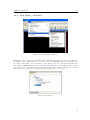
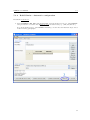
1
Licence
GIMIAS is trademarks of Center for Computational Image and Simulation Technologies in
Biomedicine (CISTIB), Universitat Pompeu Fabra (UPF), Barcelona, Spain. The documentation
for GIMIAS is freely available and distributable under the BSD License.
c 2010, Center for Computational Image and Simulation Technologies in Biomedicine
Copyright (CISTIB), Universitat Pompeu Fabra (UPF), Barcelona, Spain.
All rights reserved.
Redistribution and use in source and binary forms, with or without modification, are permitted
provided that the following conditions are met:
• Redistributions of source code must retain the above copyright notice, this list of conditions
and the following disclaimer.
• Redistributions in binary form must reproduce the above copyright notice, this list of conditions and the following disclaimer in the documentation and/or other materials provided
with the distribution.
• Neither the name of the Zang Industries nor the names of its contributors may be used
to endorse or promote products derived from this software without specific prior written
permission.
THIS SOFTWARE IS PROVIDED BY THE COPYRIGHT HOLDERS AND CONTRIBUTORS "AS IS" AND ANY EXPRESS OR IMPLIED WARRANTIES, INCLUDING, BUT NOT
LIMITED TO, THE IMPLIED WARRANTIES OF MERCHANTABILITY AND FITNESS FOR
A PARTICULAR PURPOSE ARE DISCLAIMED. IN NO EVENT SHALL THE COPYRIGHT
OWNER OR CONTRIBUTORS BE LIABLE FOR ANY DIRECT, INDIRECT, INCIDENTAL, SPECIAL, EXEMPLARY, OR CONSEQUENTIAL DAMAGES (INCLUDING, BUT NOT
LIMITED TO, PROCUREMENT OF SUBSTITUTE GOODS OR SERVICES; LOSS OF USE,
DATA, OR PROFITS; OR BUSINESS INTERRUPTION) HOWEVER CAUSED AND ON ANY
THEORY OF LIABILITY, WHETHER IN CONTRACT, STRICT LIABILITY, OR TORT (INCLUDING NEGLIGENCE OR OTHERWISE) ARISING IN ANY WAY OUT OF THE USE OF
THIS SOFTWARE, EVEN IF ADVISED OF THE POSSIBILITY OF SUCH DAMAGE.
Contents
1 Introduction
4
1.1
About GIMIAS . . . . . . . . . . . . . . . . . . . . . . . . . . . . . . . . . . . . . .
4
1.2
GIMIAS Main Features . . . . . . . . . . . . . . . . . . . . . . . . . . . . . . . . .
4
1.3
GIMIAS Users . . . . . . . . . . . . . . . . . . . . . . . . . . . . . . . . . . . . . .
7
2 Download and Install GIMIAS
8
2.1
Download GIMIAS . . . . . . . . . . . . . . . . . . . . . . . . . . . . . . . . . . . .
8
2.2
System Requirements
8
. . . . . . . . . . . . . . . . . . . . . . . . . . . . . . . . . .
3 GIMIAS Features
9
3.1
GIMIAS Graphical User Interface (GUI) . . . . . . . . . . . . . . . . . . . . . . . .
9
3.2
GIMIAS Working Area . . . . . . . . . . . . . . . . . . . . . . . . . . . . . . . . . .
10
3.2.1
View Layouts . . . . . . . . . . . . . . . . . . . . . . . . . . . . . . . . . . .
10
3.2.2
Windows . . . . . . . . . . . . . . . . . . . . . . . . . . . . . . . . . . . . .
11
3.2.3
Brightness and contrast bar . . . . . . . . . . . . . . . . . . . . . . . . . . .
13
GIMIAS Top Menu . . . . . . . . . . . . . . . . . . . . . . . . . . . . . . . . . . . .
14
3.3.1
File Menu . . . . . . . . . . . . . . . . . . . . . . . . . . . . . . . . . . . . .
14
3.3.2
Edit Menu
. . . . . . . . . . . . . . . . . . . . . . . . . . . . . . . . . . . .
19
3.3.3
View Menu . . . . . . . . . . . . . . . . . . . . . . . . . . . . . . . . . . . .
20
3.3.4
View Menu -> Windows . . . . . . . . . . . . . . . . . . . . . . . . . . . . .
21
3.3.5
View Menu -> Visualization
. . . . . . . . . . . . . . . . . . . . . . . . . .
26
3.3.6
Tools Menu . . . . . . . . . . . . . . . . . . . . . . . . . . . . . . . . . . . .
30
3.3.7
Tools Menu -> Signals . . . . . . . . . . . . . . . . . . . . . . . . . . . . . .
30
3.3.8
Tools Menu -> Surface Editing . . . . . . . . . . . . . . . . . . . . . . . . .
30
3.3.9
Tools Menu -> Statistics
. . . . . . . . . . . . . . . . . . . . . . . . . . . .
30
3.3.10 Tools Menu -> Mesh Processing . . . . . . . . . . . . . . . . . . . . . . . .
30
3.3.11 Tools Menu -> Images Processing . . . . . . . . . . . . . . . . . . . . . . .
30
3.3
3
3.4
3.5
3.3.12 Selection Menu . . . . . . . . . . . . . . . . . . . . . . . . . . . . . . . . . .
31
GIMIAS Toolbars . . . . . . . . . . . . . . . . . . . . . . . . . . . . . . . . . . . . .
34
3.4.1
Layout Toolbar . . . . . . . . . . . . . . . . . . . . . . . . . . . . . . . . . .
34
3.4.2
Working Area Toolbar . . . . . . . . . . . . . . . . . . . . . . . . . . . . . .
35
3.4.3
IO Toolbar . . . . . . . . . . . . . . . . . . . . . . . . . . . . . . . . . . . .
35
3.4.4
Windows Toolbar . . . . . . . . . . . . . . . . . . . . . . . . . . . . . . . . .
36
3.4.5
Selection Toolbar . . . . . . . . . . . . . . . . . . . . . . . . . . . . . . . . .
36
3.4.6
Appearance Toolbar . . . . . . . . . . . . . . . . . . . . . . . . . . . . . . .
37
3.4.7
MultiRenderWindow Toolbar . . . . . . . . . . . . . . . . . . . . . . . . . .
37
Useful commands . . . . . . . . . . . . . . . . . . . . . . . . . . . . . . . . . . . . .
38
4 GIMIAS Plugins
39
4.1
DICOM Plug-in . . . . . . . . . . . . . . . . . . . . . . . . . . . . . . . . . . . . . .
39
4.2
Scene View Plug-in . . . . . . . . . . . . . . . . . . . . . . . . . . . . . . . . . . . .
41
4.3
Sandbox Plug-in . . . . . . . . . . . . . . . . . . . . . . . . . . . . . . . . . . . . .
41
4.4
Manual Segmentation Plug-in . . . . . . . . . . . . . . . . . . . . . . . . . . . . . .
42
4.4.1
Multilevel ROIs . . . . . . . . . . . . . . . . . . . . . . . . . . . . . . . . . .
42
4.4.2
ROI statistics . . . . . . . . . . . . . . . . . . . . . . . . . . . . . . . . . . .
44
Mesh Editor Plug-in . . . . . . . . . . . . . . . . . . . . . . . . . . . . . . . . . . .
45
4.5.1
Mesh creation . . . . . . . . . . . . . . . . . . . . . . . . . . . . . . . . . . .
45
4.5.2
Extract Surface . . . . . . . . . . . . . . . . . . . . . . . . . . . . . . . . . .
46
4.5.3
Ring Cut . . . . . . . . . . . . . . . . . . . . . . . . . . . . . . . . . . . . .
47
4.5.4
Tetra Generation . . . . . . . . . . . . . . . . . . . . . . . . . . . . . . . . .
48
4.5.5
Volume Closing . . . . . . . . . . . . . . . . . . . . . . . . . . . . . . . . . .
49
4.5.6
Surface Selector . . . . . . . . . . . . . . . . . . . . . . . . . . . . . . . . . .
51
Signal Viewer Plug-in . . . . . . . . . . . . . . . . . . . . . . . . . . . . . . . . . .
53
4.6.1
Add Annotations . . . . . . . . . . . . . . . . . . . . . . . . . . . . . . . . .
53
Image Tools Plug-in . . . . . . . . . . . . . . . . . . . . . . . . . . . . . . . . . . .
55
4.7.1
Cropping Tool . . . . . . . . . . . . . . . . . . . . . . . . . . . . . . . . . .
55
4.7.2
Change Orientation . . . . . . . . . . . . . . . . . . . . . . . . . . . . . . .
56
4.7.3
Overlay Images . . . . . . . . . . . . . . . . . . . . . . . . . . . . . . . . . .
57
4.5
4.6
4.7
5 GIMIAS development framework
58
5.1
Introduction . . . . . . . . . . . . . . . . . . . . . . . . . . . . . . . . . . . . . . . .
58
5.2
GIMIAS Software Architecture . . . . . . . . . . . . . . . . . . . . . . . . . . . . .
58
5.3
GIMIAS Processing use case . . . . . . . . . . . . . . . . . . . . . . . . . . . . . . .
60
GIMIAS User Manual
5.4
0.0
Third Party Libraries . . . . . . . . . . . . . . . . . . . . . . . . . . . . . . . . . .
6 Download and Build GIMIAS
61
62
6.1
Required Tools . . . . . . . . . . . . . . . . . . . . . . . . . . . . . . . . . . . . . .
62
6.2
Check out GIMIAS from SVN repository
. . . . . . . . . . . . . . . . . . . . . . .
62
6.3
GIMIAS source code folder structure . . . . . . . . . . . . . . . . . . . . . . . . . .
63
6.4
Install and Build . . . . . . . . . . . . . . . . . . . . . . . . . . . . . . . . . . . . .
64
7 How to configure and use CSnake
65
7.1
What is CSnake? . . . . . . . . . . . . . . . . . . . . . . . . . . . . . . . . . . . . .
65
7.2
Set up CSnake . . . . . . . . . . . . . . . . . . . . . . . . . . . . . . . . . . . . . .
65
7.3
Use CSnake to build GIMIAS . . . . . . . . . . . . . . . . . . . . . . . . . . . . . .
66
7.3.1
Configure CSnake options . . . . . . . . . . . . . . . . . . . . . . . . . . . .
66
7.3.2
Configure CSnake building parameters . . . . . . . . . . . . . . . . . . . . .
67
7.3.3
Select Projects . . . . . . . . . . . . . . . . . . . . . . . . . . . . . . . . . .
68
7.3.4
Build Gimias - Automatic configuration . . . . . . . . . . . . . . . . . . . .
69
7.3.5
Build Third Party Libraries - Manual configuration . . . . . . . . . . . . . .
70
7.3.6
Build Gimias - Manual configuration . . . . . . . . . . . . . . . . . . . . . .
71
7.3.7
Save CSnake configuration . . . . . . . . . . . . . . . . . . . . . . . . . . . .
72
8 Develop your own project for GIMIAS
73
8.1
Pre-requisites . . . . . . . . . . . . . . . . . . . . . . . . . . . . . . . . . . . . . . .
73
8.2
Create a new project for GIMIAS . . . . . . . . . . . . . . . . . . . . . . . . . . . .
74
8.2.1
Create the basic folders and files . . . . . . . . . . . . . . . . . . . . . . . .
74
Create a new library in the toolkit . . . . . . . . . . . . . . . . . . . . . . . . . . .
75
8.3.1
Create the basic folders and files . . . . . . . . . . . . . . . . . . . . . . . .
75
8.3.2
Generate Visual Studio solution . . . . . . . . . . . . . . . . . . . . . . . . .
76
Create a new plug-in for GIMIAS . . . . . . . . . . . . . . . . . . . . . . . . . . . .
80
8.4.1
Create the basic folders and files . . . . . . . . . . . . . . . . . . . . . . . .
80
8.4.2
Create a new widget and a new processor . . . . . . . . . . . . . . . . . . .
81
8.4.3
Build your new plugin . . . . . . . . . . . . . . . . . . . . . . . . . . . . . .
83
8.4.4
Create UI controls with wxGlade . . . . . . . . . . . . . . . . . . . . . . . .
84
Integrate a new third party . . . . . . . . . . . . . . . . . . . . . . . . . . . . . . .
85
8.5.1
Create the basic folders and files . . . . . . . . . . . . . . . . . . . . . . . .
85
8.5.2
Include your library files . . . . . . . . . . . . . . . . . . . . . . . . . . . . .
86
8.5.3
Build the third parties for the new project . . . . . . . . . . . . . . . . . . .
88
8.3
8.4
8.5
5
Chapter 1
Introduction
1.1
About GIMIAS
GIMIAS (Graphical Interface for Medical Image Analysis and Simulation) is a software framework
designed to be an integrative tool for fast prototyping of medical applications. It is a workfloworiented environment for advanced biomedical image computing and simulations, and it can be
extended through the development of problem-specific plug-ins.
GIMIAS is particularly tailored to integrate tools from medical imaging, computational
modeling, numerical methods and computer graphics in order to provide scientific developers and
researchers with a framework for building a wide variety of tools. Multi-modal image processing,
personalized model creation, numerical simulation and visualization of simulation results are some
of the possible applications for which GIMIAS has been designed. The aim of this framework is
to combine tools from different areas of knowledge providing a framework for multi-disciplinary
research and medical study.
GIMIAS allows building medical prototypes for clinical evaluation, in the area of medical image
analysis, modeling and simulation. It simplifies the integration of tools needed to build new clinical
workflows, and the use of common libraries for user interfaces, visualization, image processing,
DICOM access etc, that are commonly used as standard in Virtual Physiological Human (VPH)
research.
GIMIAS provides a graphical user interface with all main data IO, visualization and interaction
functions for images, meshes and signals. It includes additional tools for image segmentation, mesh
editing, signal navigation and specific visualizations.
GIMIAS provides a simple Application Programming Interface (API) that permits, with
minimal effort, to test methodologies and algorithms in the form of end-user applications. The
prototypes developed on GIMIAS can be verified by end users in real scenarios and with real data
at early development stages, thus reducing the time and effort required to get new concepts from
research to the clinical environment.
Figure 1.1 shows an example of prototype developed on GIMIAS framework for cardiac
modeling and quantification applications.
1.2
GIMIAS Main Features
The main features of GIMIAS framework are the following:
6
GIMIAS User Manual
1.2
Figure 1.1: Example of GIMIAS prototype, and the steps that can be integrated into one
application
• Plugin architecture.
• Workflow management.
• Multimodal 3D image interactive visualization and time navigation.
• Supported data: 3D images, surface meshes, volumetric meshes, signals, landmarks
• Data visualization: OrthoSlice, MultiSlice, MultiViews, Direct volume rendering, XRay
rendering.
• Supported IO formats: DICOM, vtk, vti, stl, analyze, NIfTI
• Image-based analysis and functional analysis tools.
• DICOM browser/viewer and PACS connection.
• Surface mesh manipulation tools.
• Manual segmentation tools.
• Signal viewer.
• Landmark selection.
7
GIMIAS User Manual
1.2
• Image cropping.
• Based on common open source libraries (vtk, itk, mitk, dcmtk, boost, Netgen, OpenGL,
wxWidgets).
• Running on Windows platform at 32 and 64 bits.
• Beta version running on Linux platform.
• Beta version running on Mac OS X.
Figure 1.2: Example of prototype interfaces on GIMIAS. The image on the left shows the results
of a flow simulation in a vessel geometry for aneurysm treatment risk assessment. On the right a
cardiac segmentation tool that allows to build patient specific models
8
GIMIAS User Manual
1.3
1.3
GIMIAS Users
GIMIAS, as a fast prototyping open source framework, is intended mainly for two different user
profiles:
• GIMIAS for clinicians and researchers: GIMIAS based prototypes are specifically
developed for researchers who want to test methodologies and validate the practical feasibility
of research concepts. Reaserch methods and algorithms can be integrated in GIMIAS in order
to allow physicians and clinical scientists to assess and validate them as end-user applications.
• GIMIAS for developers and researchers: Users can develop new functionalities using
GIMIAS as an API framework, in order to obtain new GIMIAS based clinical prototypes,
by integrating new methodologies and/or algorithms resulting from research activity.
Figure 1.3: GIMIAS users and their interactions
9
Chapter 2
Download and Install GIMIAS
2.1
Download GIMIAS
In order to evaluate the features that are available in GIMIAS framework, the following material
can be used:
• GIMIAS framework:
Download GIMIAS Release for Windows 64 bits
Download GIMIAS Release for Windows 32 bits
Download GIMIAS Release for Mac OS X
Download GIMIAS Release for Linux
• Sample data:
Download Sample Data
Request more sample data to: [email protected].
2.2
System Requirements
GIMIAS is available for Microsoft Windows XP and Vista (x86 and x64 platforms), Mac Snow
Leopard 10.6.2 and Linux Ubuntu.
We recommend an Intel Core 2 (or similar) processor, a Nvidia GeForce 6600 or ATI Radeon
8500 (or better) graphic card and a minimum of 2GB of memory.
10
Chapter 3
GIMIAS Features
This chapter describes the main functionalities available in GIMIAS framework, which is provided
open source under a BSD licence. Additional functionalities are available in other modules (plugins) that can be dynamically loaded into GIMIAS.
3.1
GIMIAS Graphical User Interface (GUI)
GIMIAS architecture is based on the core and the plug-ins, as described in chapter 5, where
each plug-in includes specific functionalies that can be added to an application. Each plug-in can
extend the user interface and processing functionalities of GIMIAS framework. The Graphical
User Interface (GUI) will usually look like in in figure 3.1:
• the Top Menu
• the Plug-in Tabs
• the Toolbars
• the Working Area
• the Widgets
• the Signal Viewer (optional)
• the Status Bar
11
GIMIAS User Manual
3.2
Figure 3.1: GIMIAS Graphical User Interface
3.2
GIMIAS Working Area
The working area is the area of the GUI where the image can be visualized and the main interaction
functions can be performed on the image (zoom, rotate, pan, select, etc.).
3.2.1
View Layouts
The main view layouts available in the working area are:
• Standard four views layout / orthoslice view (2D views + 3D view)
• 2D views on the left and 3D view on the right
• Only 2D views
• Single view layout (X plane, Y plane, Z plane or 3D view)
To switch from one view to the other, use the buttons in the Layout Toolbar 3.4.1.
It is possible to switch to single view layout also by double-clicking on the desired view.
Double-click again to go back to the previous layout.
12
GIMIAS User Manual
3.2.2
3.2
Windows
More multirender windows can be loaded in GIMIAS Working Area. The following are the working
areas provided by default with GIMIAS:
• Single Window: The Single Window can be configured in any of the layouts described above.
• Two Windows: This working area is composed of two Multirender Windows (figures 3.2 and
3.3).
Figure 3.2: Two windows in a working area
Figure 3.3: Two windows used to compare two different stents deployed in the same vessel
• Three Windows: This working area is composed of three Multirender Windows (figure 3.4).
For each working area it is possible to link the camera position of the multirender windows.
• Multislice View: This view shows several cut planes and one 3D view. By default the cut
planes are parallel and the direction is Sagittal.
13
GIMIAS User Manual
3.2
Figure 3.4: Three windows in a working area
To change the number of windows that you want to display in your working area or to switch
to multislice visualization, use the buttons in the Working Area Toolbar (3.4.2).
Figure 3.5: Multislice View of a cardiac CT image.
14
GIMIAS User Manual
3.2.3
3.2
Brightness and contrast bar
Brightness and contrast can be adjusted by choosing the window center (or level) and width of
the image, using the bar placed on the right side of the working area. This can be done by moving
the bar or setting manually the numeric values.
Figure 3.6: Brightness and contrast bar
15
GIMIAS User Manual
3.3
3.3
GIMIAS Top Menu
3.3.1
File Menu
Figure 3.7: File Menu
• Open data file: the formats supported are DICOM (dcm or DICOMDIR files), vtk, stl,
cgns, gdf, csv, analyze, NIfTI. The data is automatically loaded in a Data Entity 1 .
DICOM files must be opened through DICOM plugin (see paragraph 4.1). When the image
of interest is added to the Data Tree, it is loaded in a Data Entity 1. In this way the image
is loaded in GIMIAS data memory and can be used by other plug-ins.
• Open directory: this menu option allows to open DICOM directories. The directory must
be opened through the DICOM plugin (see paragraph 4.1). When the image of interest is
added to the Data Tree, it is loaded in a Data Entity 1. In this way the image is loaded in
GIMIAS data memory and can be used by other plug-ins.
• Save selected data: each Data Entity in the Data Tree (see paragraph 3.3.4) can be saved
in dcm, vtk, stl, cgns, gdf, csv, analyze, NIfTI formats. The data entity currently selected
in the Data Tree will be saved. If the selected data entity represents a 4D (3D+t) data, a
number of volume images (in vtk format) equal to the number of timepoints will be saved
in the same folder (a new folder is created with the same name of the selected data entity
in the path chosen by the user).
• Save image of current 3D view: the 3D view currently displayed in GIMIAS working
area will be saved in png format
• Open session: the session saved in xml format can be opened and all Data Entities
contained in the session are loaded in the Data Tree preserving parent-child relations.
• Save session: all Data Entities in the Data Tree are saved in the same folder. The Data
List structure (parent-child relations) is stored in a xml file.
1 A Data Entity represents a single data object (e.g., medical image, transformation, surface mesh, model
simulation result, etc.). A description of GIMIAS data object model is provided in section 5.3. The Data List
contains all Data Entities currently available for processing in the application.
16
GIMIAS User Manual
3.3
• Workflow manager: this function allows to manage workflows in GIMIAS. Each GIMIAS
workflow is stored in a xml file and provides a way to organize the workflow steps and
provide the end user with a simplified navigation from the initial step to the final step. Each
workflow step (tab page) contains a set of processing steps. Each processing step can have
a set of alternatives. In addition, for each workflow step specific windows (i.e. visualization
options) can be set.
Figure 3.8: Workflow Manager
The workflow manager allows the following operations:
– New: Create a new empty Workflow
– Edit: Edit the currently selected workflow. You can also double click on the workflow
to edit
– Rename: Rename the currently selected workflow. This will also change the XML file
name
– Activate: Will change the active workflow. This button will automatically change the
perspective to Workflow and restart Gimias
– Delete: Deletes the workflow and the XML file from disk
– Import: Import an already existing workflow
– Save Layout: Save current GUI layout
The workflow editor (figure 3.9) allows to define the steps of a workflow and the content of
each workflow step.
On the left side you have all possible components that are registered in GIMIAS and can be
added to the workflow. On the right side you have the currently edited workflow.
How to edit a workflow:
1. In GIMIAS File Menu, make sure that the Plugin Perspective is selected and load all
the plugins that you need to create the workflow
2. Open the Workflow Manger, select the workflow that you want to edit and press Edit
to open the Workflow Editor.
3. Add a workflow step: right click on the Workflow name and select “Add a step”. You
can edit the workflow step name pressing F2 key.
4. Add visualization and processing functionalities to a step of the workflow: Each
component can be added to the workflow through drag and drop from the left side
to the right side. By default all common widgets will be added automatically.
17
GIMIAS User Manual
3.3
Figure 3.9: Workflow Editor
Figure 3.10: Perspective
5. Remove components: Remove all components that you do not need in your workflow
through drag and drop from the right side out of the window.
6. Change workflow steps order: You can change the workflow steps order or the processing
steps order with drag and drop over the right tree.
7. Press “Ok” button to save the changes or “Cancel” button to discard them.
18
GIMIAS User Manual
3.3
Figure 3.11: Workflow Editor: add a workflow step
Figure 3.12: Workflow Editor: add and remove components
In the figures below you can see an example of workflow created for morphological analysis
of aneurysms.
The steps of the clinical workflow are shown in figure 3.13.
Figure 3.13: Example workflow: Angio Morphology
Figure 3.14 shows the Workflow Editor for the Angio Morphology Workflow.
– Left side: the needed plugins to create this workflow are: Common, DICOMPlugin,
MeshEditorPlugin, AngioSegmentationPlugin, AngioMorphologyPlugin 2 . Common
folder contains all components registered as common for all plugin tabs.
– Right side: This workflow has 4 steps. Each step contains Processing steps and
Windows. For example “Load image data” step contains two specific windows from
DICOMPlugin: WorkingAreaPanelWidget and ConnectToPacsDialogWidget. While
Vessel Segmentation contains one processing step and 4 alternatives.
Figure 3.15 shows the GIMIAS Tabs corresponding to the workflow steps and created using
the Workflow manager.
2 The
Angio Segmentation Plugin and the Angio Morphology Plugin are not distributed with GIMIAS framework
19
GIMIAS User Manual
3.3
Figure 3.14: Angio Morphology Workflow: GIMIAS Workflow Editor
Figure 3.15: Angio Morphology Workflow: GIMIAS Tabs
• Perspective: This menu function allows to switch from Plugin to Workflow perspective.
When using Workflow perspective, all plug-ins needed for the specified workflow are loaded
automatically. When using Plugin perspective each plug-in can be loaded separately.
20
GIMIAS User Manual
3.3.2
3.3
Edit Menu
• Edit profile: Through this menu item it is possible to select the plug-ins to be loaded in
GIMIAS.
Figure 3.16: Profile Manager
21
GIMIAS User Manual
3.3.3
3.3
View Menu
Figure 3.17: View Menu
• Reset layout: resets layout to default GUI configuration
• Maximize working area: maximize the working area horizontally within the GUI
• Multirender Window:
– Lock axis: lock/unlock axis position and orientation.
– Show annotation cube: show/hide image orientation annotations
– Show corner annotations: show/hide image information
– Link planes: enable/disable possibility to change the angle of view planes
– Show landmarks labels: show/hide labels of landmarks. This functions can be used
only when landmarks are placed on the image/mesh (see landmark selector).
• Toolbars: hide/unhide toolbars (see section 3.4)
• Layout: change layout of working area (see section 3.2)
• Working areas: change the multirender windows loaded in the working area (see section 3.2)
• Windows: Through this menu item it is possible to select the widgets that will be opened and
personalize GIMIAS GUI (see 3.3.4). The panels are floating and can be placed wherever
the user prefers inside the window.
• Visualization: Through this menu item it is possible to open widgets that allow to change
visualization options (see 3.3.5).
• PACS Connect/Query/Retrieve/Send: opens the dialog window that allows to connect to
PACS, query and retrieve data.
22
GIMIAS User Manual
3.3.4
3.3
View Menu -> Windows
Figure 3.18: View Menu - Windows
Data Tree show or hide the Data Tree widget. The Data tree shows all data objects (images,
geometries, series, timepoints, etc.) that are loaded in GIMIAS memory and available for
processing. Each data object is stored in a data entity. The user can render/unrender each
data entity in GIMIAS working area by checking/unchecking the corresponding checkbox. Each
data entity can be unloaded from the data list (and from the memory) through the “Unload
selected” button or through the right mouse button (right click -> “Unload”).
Figure 3.19: Data tree
23
GIMIAS User Manual
3.3
Drag and drop data objects:
• Change parent-child relations: You can easily change the data tree order. For example, if
you open an image and a signal, they are both child of the root by default. You can drag
and drop the signal as child of the image. In this way the signal and the image will be
synchronized in time.
Figure 3.20: Change parent-child relations with drag and drop
• Change rendering order: The rendering order is automatically based on the data tree order.
To change the rendering order you can drag and drop objects. When you open two images,
the first image will be rendered first and the second image will be rendered second.
Figure 3.21: Change rendering order with drag and drop
Workflow navigation Enable/disable workflow navigation. This function allows to navigate
through the active workflow, defined by the user. It can be used only in Workflow Perspective
(see section 3.3.1 for reference on how to use the Workflow Manager).
Figure 3.22: Workflow Navigation
Time management Activate the Time Management bar, that allows to navigate the image
over time. Press play to see all timepoints of the series selected in the Data Tree.
Visual Properties Show/hide the Visual Properties widget. See paragraph 3.3.5 for information
on how to use the Visual Properties widget.
24
GIMIAS User Manual
3.3
Figure 3.23: Time management
Data Information show/hide the Data Information widget. This panel shows information on
the selected Data Entity in the Data Tree: number of slices, spacing on x, y, z axis, and origin of
the volume, data type, image modality, number of timesteps.
Figure 3.24: Data Information widget
Processing Tools: Show/hide the Tools processor widget. See section 3.3.6 for information on
the available tools.
Working area configuration: Activate the working area configuration widget.
Figure 3.25: Working Area Configuration widget
This widget allows to set the following options:
• Working Area Manager: you can change the working area configuration by choosing one of
25
GIMIAS User Manual
3.3
the available working areas, create a new working area, rename it, save it into an XML file
and delete an existing one.
Figure 3.26: Working Area Manager
• Configure Working Area:
– Manage Views: you can configure your new working area by choosing the number of
views and their arrangement within the working area, as in the example in figure 3.27
Figure 3.27: Custom Working Area
– Current View Configuration:
∗ Number of slices: set the number of slices/planes displayed in the window
∗ Apply to all: apply the view configuration settings (direction, rotation, flip) to all
views or the current view only.
∗ Current SliceView: choose the view/plane to which you want to apply the view
configuration settings (direction, rotation, flip).
∗ Direction: choose the direction of the selected view(s): Sagittal, Transversal or
Frontal.
26
GIMIAS User Manual
3.3
∗ Flip: visualize the mirror-reversal of the selected view(s) across its vertical axis
∗ Rotate: choose the rotation angle of the selected view(s)
27
GIMIAS User Manual
3.3.5
3.3
View Menu -> Visualization
Visual Properties This panel allows to change the visualization/representation settings of an
image or a geometry, such as volume rendering, lookup table, opacity.
Figure 3.28: VisualProperties: Image Settings and Volume Rendering
• Image settings (active for images only):
This tab is used to change the basic visualization of the orthoslice view of a volume image.
With the “Use color” control, the user can select and apply a color overlay on the image
(that will be applied over the predefined standard 256 gray level lookup table).
The background color control allows to change the background color of the 3D rendering
window.
The color lookup table combo box allows to select a color lookup table from a list of
predefined lookup tables. The color bar can be visualized/hidden using the corresponding
checkbox.
Note: the lookup table is applied directly to the currently set contrast window levels (i.e.
window level and width), even if the color bar always shows full scale values. This means
that the color bar represents the real image values only if the contrast window is set to full
scale.
The opacity slidebar allows to set the opacity level to each pixel of the image with respect
to the black background (the opacity is set to 100% by default).
• Volume rendering (active for images only):
In this tab it is possible to apply a volumetric renderization to a volume image and adjust
the visualization parameters in order to optimize the rendering effect. The “Enable VR”
checkbox enables Volume Rendering of the current selected image, using vtk/opengl facilities
to perform standard Volume Raycast or 3D Texture mapping of the volume data (figure 3.29).
28
GIMIAS User Manual
3.3
Figure 3.29: VisualProperties: Volume Rendering
Figure 3.30: VisualProperties: X-Ray Volume Rendering
With the “Enable XRay VR” checkbox it is possible to choose a 2D texture rendering
algorithm that performs a rendering visualization that simulates the XRay imaging technique
(figure 3.30).
The accuracy and speed of the volume rendering can be regulated by enabling/disabling
GPU acceleration and/or level of details (LOD).
To adjust the visualization of the volume rendering, it is possible to choose the most
appropriate transfer function from a list of predefined functions, in order to apply a specific
mapping for the scalar opacity, the scalar color and the gradient based opacity.
It is also possible to modify direclty the scalar opacity, the scalar color and the gradient
opacity mappings on top of the original and gradient image histogram. Each mapping
function is a piecewise linear function and each linear segment is determined by a couple of
control points.
To add a new point to a segment, simply left click on the segment. To remove an existing
point, right click on the point. Each point can be dragged horizontally or vertically along
the corresponding histogram, in order to customize the desired mapping function.
The control points of the scalar opacity mapping can only be moved horizontally, since in
29
GIMIAS User Manual
3.3
this case each point represents a specified color applied to the corresponding intensity level.
To change the color of the point, double click on it and choose the color in a standard pick
color control.
The 3 sliders in the cropping planes area allow to crop the volume rendering of the image in
the corresponding direction (the sliders are ordered as x, y, z), as shown in figure 3.31.
Figure 3.31: VisualProperties: Crop Volume Rendering
• Scalar settings (active for meshes only):
This tab is used to select which scalar array you want to visualize and adjust the visualization
parameter for the array (basically the scale and the color lookup table).
The Scalar Array drop down menu is filled with all the scalar arrays currently present in the
mesh. Simply choose the desired scalar array from the list to visualize it. Once a new scalar
array is selected, the range of visualized values is automatically set to the maximum range
of values present in the array and the currently selected color lookup table is automatically
scaled to the actual field range. You can also choose to manually specify the desired range
for the visualization, by specifying the min and max desired values and click on Select Range
button. The Automatic Range button will reset the range to the maximum available.
For each selected scalar field (and range), you can choose the desired color lookup table
from a drop down menu of preselected, standard lookup tables and eventually visualize the
colorbar in the 3D rendering window.
To enhance the visualization you can also change the background color of the 3D rendering
window.
• Lighting Settings (active for meshes only):
This tab is used to setup the lighting settings of the rendering scene.
Standard lighting parameters could be choosen, like the ambient, diffuse and specular colors,
and their multiplicative coeffecients; the opacity of the mesh and the specular power. All
this coefficients are used according to the currently selected lighting model (Phong, Gouroud
or flat shaded surface).
The mesh representation can be chosen in order to visualize it as a surface, a wireframe or
a series of points (in the latter cases, additional parameters could be choosen like the width
of the frames or the size of each point). In wireframe or points representation the above
mentioned lighting parameters are not used.
The changes to the mesh visualization can be applied in real time (by selecting interactive
apply that is active by default), otherwise they will be applied only to the sphere preview
and then to the mesh after pressing the apply button.
30
GIMIAS User Manual
3.3
Figure 3.32: VisualProperties: Lighting and Scalar Settings
Signal Viewer This function is available only when the Signal Viewer Plug-in is loaded. It
enables the visualization and navigation of signals (see section 4.6)
31
GIMIAS User Manual
3.3.6
3.3
Tools Menu
Figure 3.33: Tools Menu
3.3.7
Tools Menu -> Signals
The signals functions are active only when the Signal Viewer Plug-in is loaded. For reference on
how to use these functions, see 4.6.
3.3.8
Tools Menu -> Surface Editing
The surface editing functions are active only when the Mesh Editor Plug-in is loaded. For reference
on how to use these functions, see 4.5.
3.3.9
Tools Menu -> Statistics
ROI Statistics This function allows to propagate a ROI over time and do measurements on the
image in the selected ROI: mean, standard deviation, minimum and maximum intensity values.
It is available only when the Manual Segmentation Plug-in is loaded. See 4.4 for details.
Statistics on Tetra Mesh This function allows to calculate statistics on volumetric tetrahedral
meshes. The statistics that can be computed are: aspect ratio, min angle, edge ratio. This function
is active only when the Mesh Editor Plug-in is loaded.
3.3.10
Tools Menu -> Mesh Processing
This menu item includes generic tools for mesh processing. Some vtk and mitk filters are also
provided as external tools that can be loaded in GIMIAS GUI. Refer to the online documentation
of these filters for more information.
3.3.11
Tools Menu -> Images Processing
These tools are available only when the Image Tools Plug-in is loaded. For reference on how to use
these functions, see 4.7. This menu item also includes some vtk and mitk filters that are provided
32
GIMIAS User Manual
3.3
as external tools and can be loaded in GIMIAS GUI. Refer to the online documentation of these
filters for more information.
3.3.12
Selection Menu
Figure 3.34: Selection Menu
Landmark selector
To place a landmark:
1. choose Landmark selector from the menu Tools -> Selection -> Landmark selector or use
the button in the Selection Toolbar (see 3.4.5). The selection toolbox opens automatically
on the right side of the viewer. This widget shows the ID and Name of the landmarks placed
on the image selected as input data. The name of each landmark can be changed by typing
the new name in the Landmark Name text box.
Figure 3.35: Landmark Selector panel
2. SHIFT+Click on the image and place the Landmarks in the desired position.
Landmarks will be associated in the Data List to the image you select as input data.
The
3. The list of ID and names of the Landmarks placed on the image appears in the Landmark
Selector panel. The Landmarks can be renamed by entering the new name in the Landmark
Name text box.
4. To get the coordinates of the landmarks in mm, select the Landmarks in the Data tree, then
from the top menu select: File -> Save selected data entity.
5. Open the vtk file saved. This includes the coordinates (in mm) of the Landmarks placed on
the image.
33
GIMIAS User Manual
3.3
Figure 3.36: Add landmark points
6. To create a new set of landmarks click on New Landmarks in the selection toolbox.
34
GIMIAS User Manual
Measurement
3.3
This tool allows to measure the distance beetween two points on an image:
1. choose measurement from the menu Tools -> Selection -> Measurements or click on the
button in the Selection Toolbar (see 3.4.5)
2. SHIFT+click on the image to place two Landmarks in the desired position and obtain the
measure of their distance. The Landmarks will be associated in the data list to the image
you select as input data.
3. To save the measure, select the Measure in the Data list, then from the top menu select:
File -> Save selected data entity.
4. The vtk file saved includes the coordinates (in mm) of the landmarks placed on the image.
Figure 3.37: Measure distance between two points
Bounding Box This function allows to select a region of interest over an image using a bounding
box. To adjust the dimension of the bounding box use CTRL+Click to select the yellow balls (when
selected the ball becomes red) in the 3D view and drag the balls to move the planes of the box
(figure 3.38).
Press the export button to generate a data entity containing the bounding box, which can be
used in further processing operations or saved as vtk.
Surface This function allows to select mesh regions and perform local editing operations on the
selected regions. It is active only when the Mesh Editor Plug-in is loaded. For reference on how
to use this function, see 4.5.6.
Manual Segmentation This function allows to draw one or more regions of interest (ROIs)
manually over the image. This functionality is active only when the Manual Segmentation Plug-in
is loaded. For reference on how to use this function, see 4.4.
35
GIMIAS User Manual
3.4
Figure 3.38: Select region of interest using bounding box
3.4
GIMIAS Toolbars
Different toolbars containing quick access buttons for specific functionalities can be loaded in
GIMIAS, through the View menu.
3.4.1
Layout Toolbar
The Layout toolbar allows to change the layout of the selected window. It is possible to switch
from one layout to another also by double clicking on the desired view. The same functionalities
can be accessed through the menu View->Layout.
36
GIMIAS User Manual
3.4
Figure 3.39: GIMIAS Toolbars
Figure 3.40: GIMIAS Layout Toolbar
3.4.2
Working Area Toolbar
The Working Area Toolbar allos to manage the multirender windows loaded in GIMIAS. The
same functionalities can be accessed through the menu View->Working Areas. See section 3.2 for
a description of the available working areas.
3.4.3
IO Toolbar
The IO Toolbar allows to open and save files, and to connect to a PACS server. The same
functionalities are available also from the File Menu. See section 3.3.1 for reference of the file
formats that can be opened and saved.
Connection to PACS is available only from the DICOM Plug-in.
37
GIMIAS User Manual
3.4
Figure 3.41: GIMIAS Working Area Toolbar
Figure 3.42: GIMIAS IO Toolbar
3.4.4
Windows Toolbar
The Windows toolbar allows to select the widgets that will be opened and personalize GIMIAS
GUI. The panels are floating and can be placed wherever the user prefers inside the window. The
same functions can be accessed through the menu View->Windows. See section 3.3.4 for reference
of all available widgets.
3.4.5
Selection Toolbar
The Selection toolbar allows to select points and regions over an image or a mesh and perform
local measurements and/or operations. The same functions can be accessed through the menu
Tools -> Selection. See section 3.3.12 for reference of all available functionalities.
38
GIMIAS User Manual
3.4
Figure 3.43: GIMIAS Windows Toolbar
Figure 3.44: GIMIAS Selection Toolbar
3.4.6
Appearance Toolbar
The Appearance toolbar allows to change basic appearance settings, such as the color Lookup
Table (LUT) and opacity of an image.
3.4.7
MultiRenderWindow Toolbar
The MultiRenderWindow toolbar allows to change basic visualization settings.
39
GIMIAS User Manual
3.5
Figure 3.45: GIMIAS Appearance Toolbar
Figure 3.46: GIMIAS MultiRenderWindow Toolbar
3.5
Useful commands
Zoom/Unzoom on an image
Navigate through slices
Pan on image
Enlarge view
Maximize working area
Show annotation cube
Lock/Unlock axes
Show/Hide corner annotations
Copy mesh (one timepoint)
Paste mesh (one timepoint)
Right click on the view you want to zoom and move
the mouse forward/backward
Scroll
Click center button and move
Double click on the view you want to enlarge
F11
CTRL+A
CTRL+I
CTRL+N
CTRL+C
CTRL+V
Table 3.1: Useful commands
40
Chapter 4
GIMIAS Plugins
This section describes the plugins, which are provided with GIMIAS open source and can be
loaded at runtime in GIMIAS.
4.1
DICOM Plug-in
The DICOM plug-in allows to load and visualize DICOM data. It has its own Working Area
configuration (see figure 4.1) and all other view layouts are disabled.
Figure 4.1: Dicom Plugin
From the File menu it is possible to load DICOM Files, DICOM Directories, DICOMDIR
files. The same operations can be done using the quick access buttons available in the DICOM
IO Toolbar.
41
GIMIAS User Manual
4.1
Figure 4.2: Dicom IO Toolbar
In the DICOM plugin all DICOM data is represented as a tree in the DICOM Tree Viewer,
to facilitate the visualization of patient, study, series and time point data. Using the Space and
Time sliders it is possible to navigate through all available slices and timepoints. Click on the
“Add to datalist” button to add the selected 2D, 3D or 4D (3D + t) images to the Data Tree. In
this way they are converted into vtk format and ready to be rendered in other plugins.
42
GIMIAS User Manual
4.2
4.3
Scene View Plug-in
The Scene View plug-in provides all common visualization and processing functions of GIMIAS
framework. It does not contain any specific functionality.
Figure 4.3: Scene View Plugin
4.3
Sandbox Plug-in
The Sandbox plug-in can be used by plug-in developers as a template to create new plug-ins and
add new functionalities. It includes all coomon functionalities of GIMIAS framework. In addition,
it provides three GUI panel widgets for common operations on images and meshes: Resample
Panel Widget, Shape Scale Panel Widget, Subtract Panel Widget. Each widget allows to execute
basic processing functions thus demonstrating how to handle data objects in GIMAS, process them
through a combination of common vtk/itk filters, and render them in the working area.
43
GIMIAS User Manual
4.4
4.4
Manual Segmentation Plug-in
This plug-in contains specific functionalities for manual segmentation. It allows to draw one
or more regions of interest (ROIs) manually over an image, to propagate them over time and
do measurements on the image in the selected ROI: mean, standard deviation, minimum and
maximum intensity values.
4.4.1
Multilevel ROIs
You can enable the manual segmentation widget through the corresponding Icon in the Interactors
Toolbar or through the menu option Tools->Selection->Manual Segmentation.
In the Selection Toolbox different options will appear.
Figure 4.4: ROI Selection widget
To draw a multilevel ROI:
1. click on the image and drag to draw the ROI.
2. Apply corrections to the ROI by pressing Ctrl+left click and dragging on the image to draw
the border of the correction.
3. Scroll to navigate to another slice and draw another ROI.
Figure 4.5: Draw Region of Interest
44
GIMIAS User Manual
4.4
4. Add level: You must specify the name for the new level (zone) and then click add. Each
level will correspond to a different pixel value in the mask image. You can have up to 16
levels. Draw a ROI on the new level.
5. Select level: You can change the level using the combobox. When interacting (left mouse
button) the pixel value corresponding to the selected level will be drawn. You can change
the name of the selected level by editing directly in the combobox and pressing enter. Next
to the selected level, the color corresponding to it will appear.
6. Erase only selected color: When erasing (CTRL + Left mouse button) you can choose to
erase only the selected level or all them.
7. Lookup table: You can change the lookup table if you don’t like the default colors.
Figure 4.6 shows an example of a segmentation with 3 levels (LV epi, LV endo, RV endo): In the
Selection Toolbox different options will appear.
Figure 4.6: Manual Segmentation
The multi level ROI can be saved to disk and restored later. The level information is saved in
the VTK file header.
45
GIMIAS User Manual
4.4.2
4.4
ROI statistics
You can enable the multi ROI statistics widget through the menu option: Tools->Statistics->ROI
Statistics.
In the ROI Statistics widget you have the following options:
Figure 4.7: ROI Statistics
1. Propagate over time: This option allows the user to copy the mask image in a range of time
steps. You must specify the range setting the left and right values.
2. Measures: This shows the mean, standard deviation, minimum and maximum intensity
values of the image corresponding to the selected level and time step. You can change
the level using the combobox and the time step using the time management widget (View>Windows->Time management). When you click update the values are refreshed with the
selected level and time step.
3. Create signal: You can create a signal to compare the evolution of those values over time.
Those values can be computed using only the selected level. You can visualize the signal
using the signal viewer.
46
GIMIAS User Manual
4.5
4.5.1
4.5
Mesh Editor Plug-in
Mesh creation
This tool can be accessed through the menu Tools->Basic Surface Editing->Mesh Creation. This
function generates a volumetric mesh from 2D ROIs.
• Draw two ROIs on two non adjacent slices
• Choose Tools->Basic Surface Editing->Mesh creation
• Choose the method Delauneay Mesh or Marching Cubes
• Press Apply
Figure 4.8: Generate volumetric mesh
47
GIMIAS User Manual
4.5.2
4.5
Extract Surface
This tool can be accessed through the menu Tools->Basic Surface Editing->Extract Surface.
This tool allows to extract the main surface of a geometry. It is based on vtk filter
vtkPolyDataConnectivityFilter and extracts the largest connected region in the dataset.
1. Select the surface from which you want to extract the main surface
2. On the Top Menu open Tools->Basic Surface Editing->Extract Surface
3. The Tools widget is automatically opened in the right panel
4. Press ’Extract Surface’
5. The main surface is extracted and rendered. The new DataEntity containing the Extracted
Surface is listed in the Selection panel as a child of the entire surface.
Figure 4.9: Extract Main Surface
48
GIMIAS User Manual
4.5.3
4.5
Ring Cut
This tool can be accessed through the menu Tools->Advanced Surface Editing->Ring Cut. This
tool allows to cut a tubular geometry in two parts, in a point selected by the user.
• Select the geometry that you want to cut
• From the Top menu select Tools->Advanced Surface Editing->RingCut.
• The Tools widget is automatically opened in the right panel
• Press “NewCut”
• Select a point (SHIFT+CLICK) on the surface of the geometry: a preview ring will be drawn
around the surface in the selected point
• If the point is correctly placed in the desired position, press “Split using ring cut”, otherwise
select a different point or press “Cancel” to discard
• The geometry will be split into two parts colored in orange and cyan respectively; to keep one
of them, select the corresponding color from the drop down menu and press “Keep surface”
Figure 4.10: Ring Cut: select point
Figure 4.11: Ring Cut: split surfaces
49
GIMIAS User Manual
4.5.4
4.5
Tetra Generation
This tool can be accessed through the menu Tools->Advanced Surface Editing->Tetra Generation.
The aim of this feature is to generate a tetrahedral mesh from a surface mesh. The options that
are available come from two open source softwares Tetgen and Netgen: it follows a description of
both.
(a) Tetgen
(b) Netgen
Figure 4.12: Tetgen and Netgen GUI
• Tetgen
TetGen is a program to generate tetrahedral meshes of any 3D polyhedral domains. TetGen
generates exact constrained Delaunay tetrahedralizations, boundary conforming Delaunay
meshes, and Voronoi partitions http://tetgen.berlios.de.
How is Tetgen implemented in Gimias? The input mesh is saved to disk as
tetgeninput.stl and the filter calls the following command line:
tetgen
-pa#MaxVolume#q#AspectRatio#V
tetgeninput.stl
where MaxVolume and AspectRatio are values introduced by the user from the GUI (defaults
are 0.5 and 0.0, where 0.0 means that the option is not used).
The output is saved to disk as tetgenoutput.node tetgenoutput.ele and tetgenoutput.face and
then transformed into a vtkUnstructuredGrid. the switches that we use are the following:
-p Tetrahedralizes a piecewise linear complex (.stl file). The -p switch reads a
piecewise linear complex (PLC) stored in file .stl and generate a constrained Delaunay
tetrahedralization (CDT) of the PLC. In combination with the -q or -a switch, TetGen
will generate a quality tetrahedral mesh of the PLC.
-q Quality mesh generation. A minimum radius-edge ratio maybe specified
(default 2.0). The -q switch performs quality mesh generation by Shewchuk’s Delaunay
refinement algorithm [27]. It adds vertices to the CDT (used together with -p) or a previously
generated mesh (used together with -r) to ensure that no tetrahedra have radius-edge ratio
greater than 2.0. An alternative minimum radius-edge ratio may be specified after the q.
For a too small ratio, e.g.,smaller than 1.0, TetGen may not terminate. (AspectRatio in our
case)
-a Applies a maximum tetrahedron volume constraint. The -a switch imposes a
maximum volume constraint on all tetrahedra. If a number follows the ’a’ , no tetrahedra is
generated whose volume is larger than that number. (MaxVolume in our case)
-V Verbose: Detailed information, more terminal output.
50
GIMIAS User Manual
4.5
• Netgen
NETGEN is an automatic 3d tetrahedral mesh generator. It accepts input from constructive
solid geometry (CSG) or boundary representation (BRep) from STL file format. NETGEN
contains modules for mesh optimization and hierarchical mesh refinement (http://www.hpfem.jku.at/netgen/.
How is Netgen implemented in Gimias? A Netgen implementation of the surface
data entity is available in gimias (the same as vtkPolyData). when an algorithm that uses
netgen is called the implementation of the data entity is automatically switched to the
netgen representation. The user can specify the mesh size function by the global parameter
maximal mesh size, and can additionally restrict the mesh size in points or cubes. The
function NgGenerateVolumeMesh generates the volume mesh starting from the surface and
from the parameters:
Ng_Meshing_Parameters
// maximal mesh size
double maxh;
// safty factor for curvatures (elemetns per radius)
double curvaturesafety;
// minimal number of segments per edge
double segmentsperedge;
Default values are: 3.0, 0.2, 0.2;
4.5.5
Volume Closing
This tool can be accessed through the menu Tools->Basic Surface Editing->Volume Closing. The
aim of this tool is to close/fill the holes in a surface mesh. The user has the option to fill every
hole in the mesh or to select the hole he wants to fill in (options “Close all” and “Choose Hole”).
The output can be the surface mesh + the patches that have been computed or only the patches
(option “Patch output only” ). The user can finally choose between different methods of hole
filling in order to find the one that fits better his needs (default method SmoothToCenter).
Figure 4.13: Volume Closing GUI
• SINGLE CENTERPOINT: A single point is added in the center and then triangles are
created to cover the hole (see Figure 4.14a).
• RADIAL TRIANGLES: A series of points are added in each radius from the center (see
Figure 4.14b).
• LINEAR TO CENTER NONREDUCING TRIANGLES : A series of linearly distributed
concentric coronas with the same number of points (see Figure 4.14c).
51
GIMIAS User Manual
4.5
• LINEAR TO CENTER: A series of linearly distributed concentric coronas decreasing the
number of points towards the center (see Figure 4.14d).
• SMOOTH TO CENTER: A series of roundedly distributed concentric coronas decreasing
the number of points towards the center (default) (see Figure 4.14e).
• SMOOTH PATCH: Under development, it’s implemented but the result is not always correct
as you can see in Figure 4.14f
• CLOSE REFINER FAIRER: based on the method described in 1 three steps are performed,
closing the hole, then refining and fairing the patch (working only with option “close all”
and for flat holes) (see Figure 4.14g)
(a) SingleCenterPoint
(b) RadialTriangles
(c) LinearToCenterNonReducing
(d) LinearToCenter
(e) SmoothToCenter
(f) SmoothPatch
(g) CloseRefinerFairer
Figure 4.14: Volume closing methods
1 Liepa,
P. 2003. Filling holes in meshes
52
GIMIAS User Manual
4.5.6
4.5
Surface Selector
You can enable the surface selector through the corresponding Icon in the Interactors Toolbar or
through the menu option Tools->Selection->Surface
Figure 4.15: Surface Selector GUI and Toolbar direct access
In the Selection Toolbox different options will appear, all of them use the CTRL + Left Mouse
Button interaction, you can also choose if you want to select or to unselect:
1. TriangleSelect: allows the user to select/unselect triangle by triangle (see Figure 4.16a).
2. SphereSelect: allows the user to select/unselect a circular region, using a sphere that grows
dragging the mouse (see Figure 4.16b).
3. BrushSelect: allows the user to select/unselect a region with a brush of defined radius, by
dragging you will create a path with your brush, the size is given in function of the point
unit of the mesh, it can be changed with the combobox on the right (see Figure 4.16c).
4. Combination of different options: allows the user to change the selection type during the
selection of a specific region.
(a) TriangleSelect
(b) SphereSelect
(c) BrushSelect
Figure 4.16: Surface selection tools
Once the selection is made, one of the tools listed in the section Select Tools can be applied (a
new mesh is created so that it is possible to “undo” the operation).
53
GIMIAS User Manual
4.5
• Remove Cells option, it removes the selected cells.
• Local Refiner option, it refines the selected cells introducing points and new triangles. In
figure 4.17b the blue triangles are the new ones.
• Taubin Smooth option, it smooths the selected cells.
(a) Remove Triangles
(b) Local Refiner
(c) Taubin Smooth
Figure 4.17: Mesh editing tools applied on selections
54
GIMIAS User Manual
4.6
4.6
Signal Viewer Plug-in
The Signal Viewer plug-in allows visualization and navigation of signals. To enable the signal
visualization open the signal viewer from the menu View -> Visualization -> Signal Viewer.
4.6.1
Add Annotations
1. Right click on the point of the signal where you want to put your annotation and select “Add
annotation”. Select the annotation type you want to add or select “Add free annotation” to
freely set the name of the annotation.
Figure 4.18: Add annotation to signal
2. Drag the annoation to set the duration.
Figure 4.19: Choose annotation duration
Figure 4.20: Choose annotation duration
55
GIMIAS User Manual
4.6
3. Click on Open annotation widget to edit the annotation
Figure 4.21: Edit the annotation
56
GIMIAS User Manual
4.7
4.7
Image Tools Plug-in
These tools can be accessed through the menu Tools->Image Processing.
4.7.1
Cropping Tool
This tool allows to select a volume within the image and do a cropping of the image.
• From the Top menu select Tools->Cropping tool.
• The Cropping tool will be opened in the Tools widget in the right panel
• The bounding box will be displayed on the image
• Adjust the bounding box within the image to select the cropping area. To adjust the
bounding box use CTRL+Click to select the yellow balls (when selected the ball becomes
red) in the 3D view and drag the balls to move the planes of the box.
• When the desired volume is selected press Crop in the Tools widget
Figure 4.22: Cropping Tool
57
GIMIAS User Manual
4.7.2
4.7
Change Orientation
This tool allows to change the orientation of an image as follows:
• invert slice order
• flip up/down
• flip left/right
Figure 4.23: Change orientation of image
58
GIMIAS User Manual
4.7.3
4.7
Overlay Images
This tool allows to align and overlay pre-registered multimodal images.
Figure 4.24: Overlay Images
59
Chapter 5
GIMIAS development framework
5.1
Introduction
GIMIAS is designed to support the development of medical imaging prototypes. A customdesigned medical application can be created based on specific user requirements focused on a
clinical workflow. A customizable graphical user interface allows to show/hide default components
and create specialized components depending on the user needs: toolbars, rendering windows,
windows to configure parameters or rendering interaction.
A prototype in GIMIAS is conceived as a clinical workflow of several steps. Each step in the
workflow is a functionality and can go from a simple data transformation to a complex algorithm
and might require a user interface to interact with the image, set the parameters, launch the
algorithm and visualize the results.
To create a GIMIAS workflow, several plug-ins will be used that will provide the needed
processing and visualization functionalities. GIMIAS, as a framework, provides a set of common
functionalities for the development of the clinical prototypes
Figure 5.1: AngioMorphology clinical workflow diagram
5.2
GIMIAS Software Architecture
GIMIAS is developed using C++ programming language. The user interface is developed using
wxWidgets, thus enabling the creation of complex and cross-platform graphical components.
GIMIAS is a two layered system:
Plugin layer: Contains all plugins of GIMIAS framework like DICOM Plugin or Scene View
Plugin. These plug-ins extend the Framework layer with specific processing or visualization
functionalities.
60
GIMIAS User Manual
5.2
Framework layer: Contains 6 main components from top to bottom:
Widgets: Several widgets are available to be used by any plug-in
Interactors: GUI Interaction for data objects in the rendering scene
Kernel: Kernel objects like plug-in-manager, data container, logger, rendering tree, ...
IO: Reader and writers of different formats from and to files
Data Handling: Data types and its associated builders to create objects of each data type
and create the rendering data objects
Common Objects: GIMIAS object base class, Exceptions, container based on observer
pattern
Figure 5.2: GIMIAS Framework layers
GIMIAS common plug-ins are the Cardio Tools Plugin, Dicom Plugin, Image Tools Plugin,
Manual Segmentation Plugin, Mesh Editor Plugin, Neuro Tools Plugin, Sandbox Plugin, Scene
View Plugin, Signal Viewer Plugin. All these plug-ins are available in GIMIAS Open Source
version.
A developer can extend GIMIAS creating specific plug-ins. Specific plug-ins allow to extend
GIMIAS framework with specific processing steps like segmentation of a vessel, stenting or
morphological analysis of an intracranial aneurysm for angiography/vascular applications, or
segmentation of the heart, quantification or simulation for cardiac applications. These plug-ins
are specific for a clinical application.
GIMIAS provides an API for the plug-ins to interact with the core and the other plug-ins
of the framework. The classes that are needed for the creation of a new plug-in are: Widget
(which provides an element of the graphical user interface, arranging the layout according to
user preferences), FrontEndPlugin (which provides the main functionality of the plug-in), and
Processor (which executes an algorithm given one or more input data and generates one or more
output data). Each plugin is created as a class derived from FrontEndPlugin class. Each plug-in
contains one or more Widget classes and, for each Widget, one or more Processor classes. The
data is stored and handled using the following classes: DataEntity (holding a single data object),
DataHolder (holding observers to data) and DataEntityList (holding a list of objects available
for processing). A summary of the classes that can be used and/or extended for the creation of
plug-ins is provided in the list below.
61
GIMIAS User Manual
5.3
Figure 5.3: GIMIAS framework components overview
FrontEndPlugin: This is the base class for all the plug-ins, every new plug-in must extend
this class. It is responsible of the registration of the components that will extend GIMIAS
framework.
Widget: This class provides an element of the graphical user interface, that displays an
information arrangement changeable by the user, such as a window or a text box. The
defining characteristic of a widget is to provide a single interaction point for the direct
manipulation of a given kind of data.
Processor: This class executes one algorithm and, given on or more input data, generates one or
more output data (usually coming from the DataEntityList). A plug-in may contain more
than one Processor class. No data is stored inside the Processor.
DataEntity: This class stores and encapsulates a single data object (e.g., medical image,
transformation, surface mesh, model simulation result, etc.).
DataHolder: This class allows objects to be registered as observers of data, for instance, to be
notified when the data change.
DataEntityList: This class contains a list populated with the data entities currently available
for processing in the application. The input data that will be processed by the plug-in and
also their outputs are stored in this list. This list is available in all plug-in.
5.3
GIMIAS Processing use case
For data processing, each plug-in uses its own (one or more) Processor classes that encapsulate
the application logic indicating which algorithm needs to be executed on the data. External
algorithms (user defined or provided by a library) are called by a Processor after the required input
data have been specified. After the execution of an algorithm, the Processor notifies (through the
DataHolder) the corresponding observers that new data are available. These data can be rendered
or processed depending on the application. It is the responsibility of the plug-in to determine how
the processing pipeline continues.
In this way, the plug-in developer defines how the end-user operates over the data and
visualizes it. DataEntity encloses and represents 4D working data in a single entity that can
be modified, transformed and rendered by any plug-in. This class allows plug-ins to share data,
encapsulating its format conversion thus facilitating data exchange. For its simple architecture,
62
GIMIAS User Manual
5.4
Figure 5.4: Classes to be developed, and their associated complexity and interaction, for the
creation of a new plug-in. For the classes Widget and DataView the developer can choose either
implementing them or using the standard implementation provided by the framework
the sole specialization/implementation of three classes is enough for creating new plug-ins. In
this way, new features can be integrated very fast. The architecture is flexible to support plugins with different complexity, going from simple plug-ins (e.g., data is processed with a specific
algorithm and the results are visualized with standard viewers) to complex plug-ins (e.g., the entire
user interface can be re-designed to create a new data interaction and visualization application).
In addition to its plug-in API, the framework provides basic services which can be used by the
plug-ins:
• scientific visualization through standard screen layout (i.e., 3D plus orthogonal slicing),
• multimodal (MRI, SPECT, MSCT, US, PET) image processing,
• heterogeneous data management (images, polylines, surface geometries, volumetric meshes),
• Standard I/O formats (others can be added by the users).
Regarding interoperability with external tools, the framework allows the integration of readers
and writers for different format. A closer integration (e.g. in runtime) with other tools is possible
by developing a specific plug-in for this purpose.
5.4
Third Party Libraries
GIMIAS is built over widely used open source C++ based frameworks like The Visualization
Toolkit (VTK, supported by Kitware Inc.), The Insight Toolkit (ITK, also supported by
Kitware Inc.), The DICOM Toolkit (DCMTK, supported by Offis in Germany), Medical
Imaging Interaction Toolkit (MITK, developed at Division of Medical Informatics, Deutsches
Krebsforschungszentrum (DKFZ), Germany) and other commonly used C++ libraries (Boost,
wxWidgets, CXXTest, etc.).
63
Chapter 6
Download and Build GIMIAS
6.1
Required Tools
Before checking out and building GIMIAS, make sure that you have installed the following tools:
• A SVN client (Smart SVN or Tortoise SVN)
• A compiler (Microsoft Visual Studio 9 2008 is suggested)
• CMake 2.8
• Python 2.4, 2.5 or 2.6
• CSnake (see Chapter 7)
GIMIAS source code can be downloaded from:
Source code
SVN repository
Section 6.2 describes how to check out GIMIAS from the SVN repository. As an alternative,
GIMIAS source code can be downloaded as a .zip file. In this case, download the source code and
unzip the file in your local directory (e.g. E:/CodeGimias1_1), skip section 6.2 and go directly to
section 6.3.
6.2
Check out GIMIAS from SVN repository
If you are using SmartSVN follow the instructions below to checkout gimias:
1. Open SmartSVN
2. Select “Checkout project from repository”
3. In the “Repository” step, select “Quick checkout (less configuration)”
• Specify the URL: https://svncistib.upf.edu/repos/toolkit/gimias/stable/GIMIAS_1_1_0.
• Specify the Local Directory: beware to chose a directory path with no blank spaces and
no more than 20 characters length (e.g. E:/CodeGimias1_1).
64
GIMIAS User Manual
6.3
• click “Next”
4. Click “Finish”
5. SmartSVN will automatically do a checkout of the project
6.3
GIMIAS source code folder structure
After checkout from the svn repository, the local folder containing the code downloaded from the
repository should look like in figure 6.1.
Figure 6.1: GIMIAS source code folder structure
65
GIMIAS User Manual
6.4
The content of the “src” folder and the “Apps” folder is shown in figures 6.2 and 6.3.
Figure 6.2: content of src folder
Figure 6.3: content of Apps folder
6.4
Install and Build
This section describes the steps needed to build GIMIAS on a Windows platform. These steps
can be executed automatically or manually using CSnake.
For details on how to configure CSnake to build the third party libraries and
GIMIAS, refer to chapter 7.
1. Build and install the third party libraries: Use CSnake to build the third party libraries
included in GIMIAS. This requires the following steps:
1. configure the thirdParty folder
2. compile the third party libraries (i.e. compile CILAB_TOOLKIT.sln)
3. build the third party libraries
2. Build GIMIAS: Use CSnake to build GIMIAS. This requires the following steps:
1. Select the projects you want to compile
2. Create CMake files and run CMake
3. Compile GIMIAS solution (Gimias.sln)
66
Chapter 7
How to configure and use CSnake
7.1
What is CSnake?
CSnake is a CMake wrapper.
CMake is a cross-platform, open-source build system, used to control the software compilation
process using platform and compiler independent configuration files.
CSnake is a tool developed at CISTIB using Python language, which provides a high level
user interface for non CMake users, in order to configure and build multiplatform solutions like
GIMIAS.
7.2
Set up CSnake
1. Prerequisites:
• Python 2.4, 2.5 or 2.6
• CMake 2.8
• A compiler (on Windows machines Visual Studio 9 2008 is suggested)
2. CSnake (download)
3. Launch CSnake from the installation path
67
GIMIAS User Manual
7.3
7.3.1
7.3
Use CSnake to build GIMIAS
Configure CSnake options
In CSnake Options tab:
1. Specify the compiler: Visual Studio 9 is suggested.
• Choose Visual Studio 9 2008 if you want to build GIMIAS on a 32-bit machine
• Choose Visual Studio 9 2008 Win64 if you want to build GIMIAS on a 64-bit machine
2. Specify the path of the cmake.exe file
3. Specify the path of the python.exe file
4. Specify the path of the compiler
5. Check the “Ask to launch VisualStudio” checkbox (if you want to launch Visual Studio
automatically after configuring the solution)
68
GIMIAS User Manual
7.3.2
7.3
Configure CSnake building parameters
In CSnake Context tab:
1. In Build folder specify a folder in which the solution for Gimias will be created (e.g. /Bin)
2. In Root Folders specify the folder for the source file (e.g. GimiasCode/src )
3. In ThirdParty Folders/Root Folder specify the root folder for the Third Parties (e.g.
GimiasCode/thirdParty this option will be automatically given by CSnake )
4. In ThirdParty Folders/Build Folder specify a folder in which the solution for the Third
Parties will be created (e.g. Bin/thirdParty this option will be automatically given by
CSnake)
5. In CSnake File specify the python file that contains the parameters for Gimias configuration
(e.g./src/Apps/Gimias/csnGIMIAS.py)
6. Press the Update button
Note: the update button loads all available istances for the project. It can be used also to
reactivate all buttons (as you will see in the next steps, each button is disabled after the relevant
step is completed).
69
GIMIAS User Manual
7.3.3
7.3
Select Projects
In the Select Project tab:
• Choose the plugins you want to compile
• Leave all other checkbox unchecked
70
GIMIAS User Manual
7.3.4
7.3
Build Gimias - Automatic configuration
In CSnake Context tab:
1. Press Configure All: This will automatically perform all steps needed to build GIMIAS
and generate the executable file Gimias.exe in your build folder (e.g. /Bin/bin/Release )
To perform all the steps to build GIMIAS manually, you can follow the instructions provided
in the following paragraphs.
71
GIMIAS User Manual
7.3.5
7.3
Build Third Party Libraries - Manual configuration
In order to build the third party libraries manually (Advanced users) you need to complete the
following steps. In CSnake Context tab:
1. Press Configure Third Party Folder: this will create a Visual Studio solution
(CILAB_TOOLKIT.sln) for the thirdparties in the folder /Bin/thirdParty.
2. Open the Visual Studio solution. If you checked the option Ask to launch VisualStudio
checkbox in the Options tab, the solution will be automatically opened.
3. Compile the ThirdParties in VisualStudio.
11CSnakeContextC
72
GIMIAS User Manual
7.3.6
7.3
Build Gimias - Manual configuration
After you built the third parties, in order to build GIMIAS manually (Advanced users) you need
to complete the following steps. In CSnake Context tab:
1. Press Create CMake files and run CMake: this will create a Visual Studio solution
(gimias.sln) for Gimias in the folder /Bin/executable/gimias
2. Press Install Files to Build Folder
3. Press Launch IDE
4. Compile Gimias in Visual Studio
73
GIMIAS User Manual
7.3.7
7.3
Save CSnake configuration
To save the CSnake configuration:
1. Open the top menu ’File’
2. Click on ’Save’ or ’Save As’ and choose the file where you want to save your CSnake
configuration (e.g. contextMyApplication.CSnakeGUI for a GIMIAS version containing your
application, or context32.CSnakeGUI for your 32bit version of GIMIAS, or context64.CSnakeGUI
for your 64bit version of GIMIAS
3. Configure CSnake according to your needs, as described in the paragraphs above.
4. CSnake will ask you to save the current configuration in your .CSnakeGUI file, when you
close it.
To open a saved CSnake configuration:
1. Open the top menu ’File’
2. Click on ’Open’ and choose the .CSnakeGUI file containing the configuration that you want
to open
3. The selected configuration will be loaded in CSnake. CSnake will ask you to save all changes
done to the current configuration when you close it
74
Chapter 8
Develop your own project for
GIMIAS
This chapter describes how to add your own project to GIMIAS. This can apply to one or more
of the following cases:
1. Create a new library in the toolkit.
2. Integrate a new library in GIMIAS as third party, including either the source code or the
precompiled library.
3. Create a new plug-in in GIMIAS, to call functions already available in GIMIAS, or functions
belonging to the new module in the toolkit, or functions belonging to the new third party
library.
8.1
Pre-requisites
1. Before using this tutorial you need to download and build GIMIAS, following the “How to
build GIMIAS” tutorial.
2. In order to develop a new application in GIMIAS, make sure that you have installed the
following tools:
• A SVN client (Smart SVN or Tortoise SVN)
• A compiler (Microsoft Visual Studio 9 2008 is suggested)
• CMake 2.8
• CSnake 2.4.0
• Python 2.4, 2.5 or 2.6
• wxGlade
3. Donwnload the StartNewModule tool and install it on your machine.
75
GIMIAS User Manual
8.2
8.2.1
8.2
Create a new project for GIMIAS
Create the basic folders and files
In order to generate the folder structure and the basic files needed for your new project, run the
StartNewModule tool from the installation path.
1. Specify the name of the new project in the Name field (e.g. MyProject)
2. Specify the path where the new project will be created in the Root path field (e.g. your
local drive)
3. Select Project in the Type combo box
Figure 8.1: Create a new project for GIMIAS using the Start New Module tool
The tool will create a new folder ’MyProject’. The content of this folder is shown in figure 8.2.
Figure 8.2: Folder structure of the new project
76
GIMIAS User Manual
8.3
8.3.1
8.3
Create a new library in the toolkit
Create the basic folders and files
In order to generate the folder structure and the basic files needed for your new library, run the
StartNewModule tool from the installation path.
1. Specify the name of the new library in the Name field (e.g. MyLib)
2. Specify the path where the new library will be created in the Root path field (e.g.
MyProject/MyProject_src/modules)
3. Select Library in the Type combo box
4. Specify csnMyProjectToolkit.py in the Toolkit csn file field
5. Press Start New Module
Figure 8.3: Create a new library in the toolkit using the Start New Module tool
The tool will create a new folder ’MyLib’ in the ’modules’ folder. The content of this folder is
shown in figure 8.4.
77
GIMIAS User Manual
8.3
Figure 8.4: content of MyLib folder
The new library will also be added to the python file csnMyProjectToolkit.py.
Figure 8.5: MyLib is added to csnMyProjectToolkit.py
8.3.2
Generate Visual Studio solution
1. Edit the python file for the new MyLib library:
• specify all dependencies of the new library. For instance, if your new library will use
vtk functions, include vtk in the projects as follows: myLib.AddProjects([baseLib,
vtk])
• specify all library modules. The library module created by default is ’tlFirst’ and
includes template files (.cpp and .h) containing one template class. To create
your own classes it is suggested to make a copy of the ’tlFirst’ folder, rename it
(e.g. ’tlMyClass’), rename the source and include files (e.g. ’tlMyClass.cpp’ and
78
GIMIAS User Manual
8.3
’tlMyClass.h’) contained in the folder and include it in the library modules, as follows:
myLib.AddLibraryModules([“tlMyClass]“).
Figure 8.6: edit the python file for the new MyLib module
79
GIMIAS User Manual
8.3
2. Open CSnake, specify the new MyLib library as the source file and generate the MyLib
solution:
1. press Update and select the Instance mylib
2. press Create CMake files and Run CMake
3. press Launch IDE
Figure 8.7: generate Visual Studio solution for MyLib module
3. Implement your class
• in the Visual Studio solution of your new module edit tlMyClass.cpp and tlMyClass.h
to implement your class (e.g. ’MyClass’)
80
GIMIAS User Manual
8.3
4. Implement your application
• Rename the ’tlAppFirst’ folder and the ’tlAppFirst.cpp’ with the name of your
application (e.g. ’tlMyApp’)
• Edit ’csnMyLibApps.py’ and include your application: myLibApps.AddApplications([
“tlMyApp”])
• Open CSnake, specify csnMyLibApps.py as CSnake file, and press update
• press Create CMake files and Run CMake
• press Launch IDE
• compile the solution in Visual Studio
Figure 8.8: Generate your MyLib application
81
GIMIAS User Manual
8.4
8.4
Create a new plug-in for GIMIAS
This section describes how to create a new plugin for GIMIAS.
8.4.1
Create the basic folders and files
In order to generate the folder structure and the basic files needed for your new plug-in, run the
StartNewModule tool from the installation path.
1. Specify the name of your new plugin in the Name field (e.g. MyPlugin)
2. Specify the folder where you want to put your new plugin in the Root field (e.g.
MyProject/MyProject_src/plugins)
3. Select GIMIAS Plugin in the Type combo box
4. Specify the Toolkit csn file (e.g. csnMyProjectToolkit.py)
5. Specify the Gimias csn file (e.g. csnMyProject.py)
6. Press the Start New Module button
Figure 8.9: Create a new plugin for GIMIAS using the StartNewModule tool
The new plugin folder is created in the specified Root Path and the new plugin is added to the
python file csnMyProjectPlugins.py.
82
GIMIAS User Manual
8.4
Figure 8.10: MyPlugin is added to csnMyProject.py
8.4.2
Create a new widget and a new processor
Use StartNewModule to add a new functionality to your plugin.
1. Specify the name of the new functionality in the Name field (e.g. MyFunctionality)
2. Specify the plugin in which you want to add the new functionality in the Root field
(e.g. MyProject/MyProject_src/plugins/MyPlugin)
3. Select GIMIAS Plugin Widget in the Type combo box
4. Press the Start New Module button. A new panel widget and a new processor will be
automatically added to the plugin.
Figure 8.11: Create a new widget and a new processor using the StartNewModule tool
This will create in your plugin folder:
• a new folder containing the new panel widget
83
GIMIAS User Manual
8.4
Figure 8.12: New widget files
Figure 8.13: New processor
• a new folder containing the new processor
84
GIMIAS User Manual
8.4.3
8.4
Build your new plugin
Use CSnake to build the GIMIAS solution containing your new plugin. Open CSnake, specify
csnMyProject.py as the source file and generate the new Gimias solution:
1. press Update and select the Instance gimias
2. press Create CMake files and Run CMake
3. press Launch IDE
4. compile Gimias in Visual Studio
Figure 8.14: Build your new plugin
85
GIMIAS User Manual
8.4.4
8.4
Create UI controls with wxGlade
In /MyProject_src/plugins/MyPlugin/widgets/MyPluginMyFunctionalityPanelWidget open MyPluginMyFunctional
using wxGlade.
1. Add all the needed controls to the widget
Figure 8.15: Add controls to the widget using wxGlade
2. Generate Code
Figure 8.16: Generate code for the GUI
86
GIMIAS User Manual
8.5
8.5
Integrate a new third party
This section describes how to integrate in GIMIAS a new Third Party (your external library or
dll ).
8.5.1
Create the basic folders and files
In order to generate the folder structure and the basic files needed for your new third party, run
the StartNewModule tool from the installation path.
1. Specify the name of the new third party in the Name field (e.g. MyThirdParty)
2. Specify the path where the new third party will be created in the Root path field (e.g.
MyProject/MyProject_src/thirdparties)
3. Select ThirdParty in the Type combo box
4. Specify csnMyProjectToolkit.py in the Toolkit csn file field
5. Press Start New Module
Figure 8.17: Create a new module in the toolkit using the Start New Module tool
The tool will create a new folder ’MyThirdParty’ in ’thirdparties’ folder. The content of this
folder is shown in figure 8.18.
The new third party will also be added to the python file csnMyProjectToolkit.py.
87
GIMIAS User Manual
8.5
Figure 8.18: Content of the new third party folder
8.5.2
Include your library files
The library that you want to integrate in GIMIAS, should at least include the following:
• Main header file (MyThirdParty.h)
• Dynamic library (MyThirdParty.dll)
• Import library (MyThirdParty.lib)
To include MyThirdParty within the Third Party libraries, you need to copy your library header
file in the folder /MyProject/MyProject_src/thirdparties/MyThirdParty/include, and the .lib and
.dll files in /MyProject/MyProject_src/thirdparties/MyThirdParty/lib.
88
GIMIAS User Manual
8.5
Now you need to edit in MyThirdParty folder the CMake and CSnake files needed to configure
the project:
• CMakeLists (used by CMake): The CMakeLists.txt defines the paths of the libraries and
the include files and the libraries to be included.
Add here the name of your lib files for the release and debug version.
Figure 8.19: Edit CMakeLists.txt with the name of the new lib
• csnMyThirdParty.py (Used by CSnake): Add here the name of your dll files for the release
and debug version.
Figure 8.20: Edit csnMyThirdParty.py with the name of the new dll
89
GIMIAS User Manual
8.5.3
.0
Build the third parties for the new project
Use CSnake to build the solution containing your new third party. Open CSnake and configure it
as in figure
Figure 8.21: Build the third parties for the new project
Build the third parties:
1. press Update and select the Instance myproject
2. press Configure Third Party Folders
3. press Launch IDE
4. compile the third parties in Visual Studio
90