1
Mars Manual
ES3
August 3, 2012
Contents
1 Introduction
1.1 The Lattice Discrete Particle Model
1.2 Fragmentation of Weapon Casings .
1.3 Nano-Scale Modeling of C-S-H . . .
1.4 Parallelization . . . . . . . . . . . .
1.5 Vehicle Response to Blast . . . . .
1.6 Laceration of Plates and Shells . .
1.7 Steel Plates Structures . . . . . . .
(LDPM)
. . . . . .
. . . . . .
. . . . . .
. . . . . .
. . . . . .
. . . . . .
.
.
.
.
.
.
.
.
.
.
.
.
.
.
.
.
.
.
.
.
.
.
.
.
.
.
.
.
.
.
.
.
.
.
.
.
.
.
.
.
.
.
.
.
.
.
.
.
.
.
.
.
.
.
.
.
.
.
.
.
.
.
.
.
.
.
.
.
.
.
.
.
.
.
.
.
.
.
.
.
.
.
.
.
.
.
.
.
.
.
.
.
.
.
.
.
.
.
.
.
.
.
.
.
.
8
9
9
10
10
10
10
10
2 Available Documentation
10
3 Code Architecture and Input Format
3.1 Major Syntax Rules . . . . . . . . . . . . . . . . . . . . . . . . . . . . . .
3.2 The Solver Loop . . . . . . . . . . . . . . . . . . . . . . . . . . . . . . .
11
13
13
4 Control Parameters
4.1 Unit Systems . . . . . . . . .
4.1.1 Dimensional Units . .
4.2 Actions . . . . . . . . . . . .
4.2.1 Go Interactive . . . . .
4.2.2 Print Progress Line . .
4.2.3 Write Restart File . .
4.2.4 Execute Function . . .
4.2.5 Flush Time Hist Files
4.2.6 Read Input File . . . .
4.2.7 Write Plot DataFile . .
4.2.8 ExecImplicitSolver . .
4.3 Time Step Control . . . . . .
4.4 Plotting Defaults . . . . . . .
4.5 Contact Defaults . . . . . . .
4.6 Global Updates . . . . . . . .
4.7 Dynamic Relaxation . . . . .
14
15
15
18
19
19
19
19
19
20
20
20
20
21
22
22
22
.
.
.
.
.
.
.
.
.
.
.
.
.
.
.
.
.
.
.
.
.
.
.
.
.
.
.
.
.
.
.
.
.
.
.
.
.
.
.
.
.
.
.
.
.
.
.
.
1
.
.
.
.
.
.
.
.
.
.
.
.
.
.
.
.
.
.
.
.
.
.
.
.
.
.
.
.
.
.
.
.
.
.
.
.
.
.
.
.
.
.
.
.
.
.
.
.
.
.
.
.
.
.
.
.
.
.
.
.
.
.
.
.
.
.
.
.
.
.
.
.
.
.
.
.
.
.
.
.
.
.
.
.
.
.
.
.
.
.
.
.
.
.
.
.
.
.
.
.
.
.
.
.
.
.
.
.
.
.
.
.
.
.
.
.
.
.
.
.
.
.
.
.
.
.
.
.
.
.
.
.
.
.
.
.
.
.
.
.
.
.
.
.
.
.
.
.
.
.
.
.
.
.
.
.
.
.
.
.
.
.
.
.
.
.
.
.
.
.
.
.
.
.
.
.
.
.
.
.
.
.
.
.
.
.
.
.
.
.
.
.
.
.
.
.
.
.
.
.
.
.
.
.
.
.
.
.
.
.
.
.
.
.
.
.
.
.
.
.
.
.
.
.
.
.
.
.
.
.
.
.
.
.
.
.
.
.
.
.
.
.
.
.
.
.
.
.
.
.
.
.
.
.
.
.
.
.
.
.
.
.
.
.
.
.
.
.
.
.
.
.
.
.
.
.
.
.
.
.
.
.
.
.
.
.
.
.
.
.
.
.
.
.
.
.
.
.
.
.
.
.
.
.
.
.
.
.
.
.
.
.
.
.
.
.
.
.
.
.
.
.
.
.
.
.
.
.
.
.
.
.
.
.
.
.
4.8
4.9
Gravity . . . . . . . . . . . . . . . . . . . . . . . . . . . . . . . . . . . .
Plugins . . . . . . . . . . . . . . . . . . . . . . . . . . . . . . . . . . . . .
5 Miscellanous Objects
5.1 Reference Systems . . . . . . . . . . . . . . . . . . .
5.1.1 Cartesian RefSys . . . . . . . . . . . . . . . .
5.1.2 Cylindrical RefSys . . . . . . . . . . . . . . .
5.1.3 Spherical RefSys . . . . . . . . . . . . . . . .
5.2 Load Curves . . . . . . . . . . . . . . . . . . . . . . .
5.2.1 Load Curves Lists . . . . . . . . . . . . . . . .
5.3 Built-In Blast Loads . . . . . . . . . . . . . . . . . .
5.3.1 ConWep . . . . . . . . . . . . . . . . . . . . .
5.4 Random Number Distributions . . . . . . . . . . . .
5.4.1 Weibull distribution . . . . . . . . . . . . . .
5.4.2 Uniform distribution . . . . . . . . . . . . . .
5.4.3 Gaussian distribution . . . . . . . . . . . . . .
5.4.4 Fuller distribution . . . . . . . . . . . . . . . .
5.5 Colors . . . . . . . . . . . . . . . . . . . . . . . . . .
5.6 Strain Gages . . . . . . . . . . . . . . . . . . . . . . .
5.6.1 Strain-Gage for hexahedral solid lists . . . . .
5.6.2 Strain-Gage for tetrahedral solid lists . . . . .
5.6.3 Strain-Gage for quadrilateral shell lists . . . .
5.6.4 TimeHistories . . . . . . . . . . . . . . . . . .
5.7 Accelerometer . . . . . . . . . . . . . . . . . . . . . .
5.7.1 Attached to quadrilateral surfaces . . . . . . .
5.7.2 Attached to triangular surfaces . . . . . . . .
5.7.3 Attached to the surfaces of a beam element .
5.7.4 TimeHistories . . . . . . . . . . . . . . . . . .
5.8 Equations . . . . . . . . . . . . . . . . . . . . . . . .
5.8.1 Pressurized Volume . . . . . . . . . . . . . . .
5.8.2 Injected Fluid . . . . . . . . . . . . . . . . . .
5.8.3 Adiabatic Compression . . . . . . . . . . . . .
5.9 Material Models . . . . . . . . . . . . . . . . . . . . .
5.9.1 Elastic Material Model . . . . . . . . . . . . .
5.9.2 Elastio-plastic Material Model . . . . . . . . .
5.9.3 Rate Sensistive Elasto-plastic Material Model
5.9.4 Johnson-Cook Model . . . . . . . . . . . . . .
5.9.5 LDPM Concrete Material Model . . . . . . .
5.9.6 RCI Rebar-Concrete Interaction Model . . . .
5.9.7 LDPM Concrete-Fiber Interaction Model . . .
5.9.8 Simple Cap Concrete Material Model . . . . .
5.9.9 K&C Concrete Material Model . . . . . . . .
5.10 Functions / Macros . . . . . . . . . . . . . . . . . . .
5.11 Pre-Set Test Simulations . . . . . . . . . . . . . . . .
5.11.1 Biaxial Test . . . . . . . . . . . . . . . . . . .
2
.
.
.
.
.
.
.
.
.
.
.
.
.
.
.
.
.
.
.
.
.
.
.
.
.
.
.
.
.
.
.
.
.
.
.
.
.
.
.
.
.
.
.
.
.
.
.
.
.
.
.
.
.
.
.
.
.
.
.
.
.
.
.
.
.
.
.
.
.
.
.
.
.
.
.
.
.
.
.
.
.
.
.
.
.
.
.
.
.
.
.
.
.
.
.
.
.
.
.
.
.
.
.
.
.
.
.
.
.
.
.
.
.
.
.
.
.
.
.
.
.
.
.
.
.
.
.
.
.
.
.
.
.
.
.
.
.
.
.
.
.
.
.
.
.
.
.
.
.
.
.
.
.
.
.
.
.
.
.
.
.
.
.
.
.
.
.
.
.
.
.
.
.
.
.
.
.
.
.
.
.
.
.
.
.
.
.
.
.
.
.
.
.
.
.
.
.
.
.
.
.
.
.
.
.
.
.
.
.
.
.
.
.
.
.
.
.
.
.
.
.
.
.
.
.
.
.
.
.
.
.
.
.
.
.
.
.
.
.
.
.
.
.
.
.
.
.
.
.
.
.
.
.
.
.
.
.
.
.
.
.
.
.
.
.
.
.
.
.
.
.
.
.
.
.
.
.
.
.
.
.
.
.
.
.
.
.
.
.
.
.
.
.
.
.
.
.
.
.
.
.
.
.
.
.
.
.
.
.
.
.
.
.
.
.
.
.
.
.
.
.
.
.
.
.
.
.
.
.
.
.
.
.
.
.
.
.
.
.
.
.
.
.
.
.
.
.
.
.
.
.
.
.
.
.
.
.
.
.
.
.
.
.
.
.
.
.
.
.
.
.
.
.
.
.
.
.
.
.
.
.
.
.
.
.
.
.
.
.
.
.
.
.
.
.
.
.
.
.
.
.
.
.
.
.
.
.
.
.
.
.
.
.
.
.
.
.
.
.
.
.
.
.
.
.
.
.
.
.
.
.
.
.
.
.
.
.
.
.
.
.
.
.
.
.
.
.
.
.
.
.
23
24
25
25
25
25
26
26
27
27
28
29
29
30
30
30
31
31
32
32
32
33
33
34
34
34
34
35
35
35
35
36
36
37
38
39
40
41
42
43
43
44
47
47
5.11.2 Triaxial Test . . . . . . . . . . . . . . . . . . . . . . . . . . . . . .
5.11.3 Colorado Test . . . . . . . . . . . . . . . . . . . . . . . . . . . . .
6 Nodes and Particle Lists
6.1 Node Lists . . . . . . . . . . . . . . .
6.1.1 Select Commands . . . . . . .
6.1.2 Set Commands . . . . . . . .
6.1.3 Scale Commands . . . . . . .
6.1.4 Translate/Rotate Commands
6.1.5 Other Commands . . . . . . .
6.1.6 Time History Commands . . .
6.1.7 Plot List Commands . . . . .
6.1.8 Nodal Rotations . . . . . . . .
6.1.9 Extract Commands . . . . . .
6.1.10 Insert Commands . . . . . . .
6.1.11 Discrete Element Commands .
6.2 MacroParticle Lists . . . . . . . . . .
6.2.1 Flex 4-Sphere MacroParticle .
6.2.2 Rigid 4-Sphere MacroParticle
6.2.3 Rigid 3-Sphere MacroParticle
.
.
.
.
.
.
.
.
.
.
.
.
.
.
.
.
.
.
.
.
.
.
.
.
.
.
.
.
.
.
.
.
.
.
.
.
.
.
.
.
.
.
.
.
.
.
.
.
.
.
.
.
.
.
.
.
.
.
.
.
.
.
.
.
.
.
.
.
.
.
.
.
.
.
.
.
.
.
.
.
.
.
.
.
.
.
.
.
.
.
.
.
.
.
.
.
.
.
.
.
.
.
.
.
.
.
.
.
.
.
.
.
.
.
.
.
.
.
.
.
.
.
.
.
.
.
.
.
.
.
.
.
.
.
.
.
.
.
.
.
.
.
.
.
.
.
.
.
.
.
.
.
.
.
.
.
.
.
.
.
.
.
.
.
.
.
.
.
.
.
.
.
.
.
.
.
.
.
.
.
.
.
.
.
.
.
.
.
.
.
.
.
7 Edge/Truss/Beam Elements
7.1 Edge List . . . . . . . . . . . . . . . . . . . . . . . . . . .
7.1.1 Generate commands . . . . . . . . . . . . . . . . .
7.1.2 Select commands . . . . . . . . . . . . . . . . . . .
7.1.3 Make commands . . . . . . . . . . . . . . . . . . .
7.1.4 Notes . . . . . . . . . . . . . . . . . . . . . . . . .
7.1.5 Linear Elastic Beams - Uniform Cross Section . . .
7.1.6 Linear Elastic Beams - Non-Uniform Cross Section
7.1.7 Plotting options . . . . . . . . . . . . . . . . . . . .
7.2 Beam Lists . . . . . . . . . . . . . . . . . . . . . . . . . .
7.2.1 Time History Commands . . . . . . . . . . . . . . .
7.2.2 Plot Commands . . . . . . . . . . . . . . . . . . . .
7.3 Geometric Pair Detection . . . . . . . . . . . . . . . . . .
7.4 Geometric Pair-Detection . . . . . . . . . . . . . . . . . .
7.5 Master-Slave Constraints . . . . . . . . . . . . . . . . . . .
7.6 Node-Pair Attraction List . . . . . . . . . . . . . . . . . .
7.7 Node-Pair Repulsion List . . . . . . . . . . . . . . . . . . .
7.8 Node-Pair VanDerWaals List . . . . . . . . . . . . . . . . .
7.9 Node-Pair NanoParticle List . . . . . . . . . . . . . . . . .
7.10 Nano Particles . . . . . . . . . . . . . . . . . . . . . . . . .
7.10.1 Tabulated Forces . . . . . . . . . . . . . . . . . . .
7.10.2 VanDerWaals Forces . . . . . . . . . . . . . . . . .
7.10.3 Plotting Options . . . . . . . . . . . . . . . . . . .
7.11 Node-Pair Penalty Constraints . . . . . . . . . . . . . . . .
3
.
.
.
.
.
.
.
.
.
.
.
.
.
.
.
.
.
.
.
.
.
.
.
.
.
.
.
.
.
.
.
.
.
.
.
.
.
.
.
.
.
.
.
.
.
.
.
.
.
.
.
.
.
.
.
.
.
.
.
.
.
.
.
.
.
.
.
.
.
.
.
.
.
.
.
.
.
.
.
.
.
.
.
.
.
.
.
.
.
.
.
.
.
.
.
.
.
.
.
.
.
.
.
.
.
.
.
.
.
.
.
.
.
.
.
.
.
.
.
.
.
.
.
.
.
.
.
.
.
.
.
.
.
.
.
.
.
.
.
.
.
.
.
.
.
.
.
.
.
.
.
.
.
.
.
.
.
.
.
.
.
.
.
.
.
.
.
.
.
.
.
.
.
.
.
.
.
.
.
.
.
.
.
.
.
.
.
.
.
.
.
.
.
.
.
.
.
.
.
.
.
.
.
.
.
.
.
.
.
.
.
.
.
.
.
.
.
.
.
.
.
.
.
.
.
.
.
.
.
.
.
.
.
.
.
.
.
.
.
.
.
.
.
.
.
.
.
.
.
.
.
.
.
.
.
.
.
.
.
.
.
.
.
.
.
.
.
.
.
.
.
.
.
48
48
.
.
.
.
.
.
.
.
.
.
.
.
.
.
.
.
49
49
50
51
51
52
52
53
53
56
57
57
58
58
59
59
60
.
.
.
.
.
.
.
.
.
.
.
.
.
.
.
.
.
.
.
.
.
.
.
60
60
62
65
66
66
67
68
68
69
70
71
74
74
74
74
75
75
75
76
76
77
77
78
8 Triangular Faces and Shell Elements
8.1 Triangular Face Lists . . . . . . . . . . .
8.1.1 Select commands . . . . . . . . .
8.1.2 Generate commands . . . . . . .
8.1.3 Make commands . . . . . . . . .
8.1.4 How to make sublists . . . . . . .
8.2 Wet Triang Face List . . . . . . . . . . .
8.2.1 Uniform Pressure . . . . . . . . .
8.2.2 Uniform Pressure - Constant Face
8.2.3 Multiple Pressure Histories . . . .
8.3 Triangular DKT Shell List . . . . . . . .
8.3.1 Time Histories . . . . . . . . . .
9 Quadrilateral Faces and Shell Elements
9.1 Quadrilateral Face List . . . . . . . . . .
9.1.1 Select commands . . . . . . . . .
9.1.2 Generate commands . . . . . . .
9.1.3 Make commands . . . . . . . . .
9.2 Pressurized Quad Face List . . . . . . .
9.2.1 Uniform Pressure . . . . . . . . .
9.2.2 Special Loads . . . . . . . . . . .
9.2.3 Multiple Pressure Histories . . . .
9.3 Quad Shell Lists . . . . . . . . . . . . .
9.3.1 Weibull distribution . . . . . . .
9.3.2 Plot commands . . . . . . . . . .
. . . .
. . . .
. . . .
. . . .
. . . .
. . . .
. . . .
Areas
. . . .
. . . .
. . . .
.
.
.
.
.
.
.
.
.
.
.
.
.
.
.
.
.
.
.
.
.
.
.
.
.
.
.
.
.
.
.
.
.
10 Tetrahedral Solid List
10.1 Examples . . . . . . . . . . . . . . . . . . . .
10.2 Select Commands . . . . . . . . . . . . . . . .
10.3 Generate Commands . . . . . . . . . . . . . .
10.4 Make Commands . . . . . . . . . . . . . . . .
10.5 Time History Commands . . . . . . . . . . . .
10.6 Plot Attribute Commands . . . . . . . . . . .
10.7 Viscous Tets . . . . . . . . . . . . . . . . . . .
10.8 Spatial Field Functions . . . . . . . . . . . . .
10.9 Ten-Node Tet Elements . . . . . . . . . . . . .
10.9.1 Ten-Node Small Deformation Element
10.9.2 Ten-Node Large Deformation Element
11 Lattice Discrete Particle Model
11.1 Input commands . . . . . . . .
11.2 Model Generation . . . . . . . .
11.2.1 Box . . . . . . . . . . .
11.2.2 Cylinder . . . . . . . . .
11.2.3 Sphere . . . . . . . . . .
.
.
.
.
.
.
.
.
.
.
4
.
.
.
.
.
.
.
.
.
.
.
.
.
.
.
.
.
.
.
.
.
.
.
.
.
.
.
.
.
.
.
.
.
.
.
.
.
.
.
.
.
.
.
.
.
.
.
.
.
.
.
.
.
.
.
.
.
.
.
.
.
.
.
.
.
.
.
.
.
.
.
.
.
.
.
.
.
.
.
.
.
.
.
.
.
.
.
.
.
.
.
.
.
.
.
.
.
.
.
.
.
.
.
.
.
.
.
.
.
.
.
.
.
.
.
.
.
.
.
.
.
.
.
.
.
.
.
.
.
.
.
.
.
.
.
.
.
.
.
.
.
.
.
.
.
.
.
.
.
.
.
.
.
.
.
.
.
.
.
.
.
.
.
.
.
.
.
.
.
.
.
.
.
.
.
.
.
.
.
.
.
.
.
.
.
.
.
.
.
.
.
.
.
.
.
.
.
.
.
.
.
.
.
.
.
.
.
.
.
.
.
.
.
.
.
.
.
.
.
.
.
.
.
.
.
.
.
.
.
.
.
.
.
.
.
.
.
.
.
.
.
.
.
.
.
.
.
.
.
.
.
.
.
.
.
.
.
.
.
.
.
.
.
.
.
.
.
.
.
.
.
.
.
.
.
.
.
.
.
.
.
.
.
.
.
.
.
.
.
.
.
.
.
.
.
.
.
.
.
.
.
.
.
.
.
.
.
.
.
.
.
.
.
.
.
.
.
.
.
.
.
.
.
.
.
.
.
.
.
.
.
.
.
.
.
.
.
.
.
.
.
.
.
.
.
.
.
.
.
.
.
.
.
.
.
.
.
.
.
.
.
.
.
.
.
.
.
.
.
.
.
.
.
.
.
.
.
.
.
.
.
.
.
.
.
.
.
.
.
.
.
.
.
.
.
.
.
.
.
.
.
.
.
.
.
.
.
.
.
.
.
.
.
.
.
.
.
.
.
.
.
.
.
.
.
.
.
.
.
.
.
.
.
.
.
.
.
.
.
.
.
.
.
.
.
.
.
.
.
.
.
.
.
.
.
.
.
.
.
.
.
.
.
.
.
.
.
.
.
.
.
.
.
.
.
.
.
.
.
.
.
.
.
.
.
.
.
.
.
.
.
.
.
.
.
.
.
.
.
.
.
.
.
.
.
.
.
.
.
.
.
.
.
.
.
.
.
.
.
.
.
.
.
.
.
.
.
.
.
.
.
.
.
.
.
.
.
.
.
.
.
.
.
.
.
.
.
.
.
.
.
.
.
.
.
.
.
.
.
.
.
.
78
78
80
80
82
82
84
84
85
85
86
87
.
.
.
.
.
.
.
.
.
.
.
87
87
88
89
91
92
92
93
93
94
95
95
.
.
.
.
.
.
.
.
.
.
.
96
98
98
98
100
101
101
101
102
103
105
105
.
.
.
.
.
105
106
110
111
111
112
11.2.4 DogBone Specimen . . . . . . . . .
Time Histories . . . . . . . . . . . . . . . .
Using Pre-Generated Meshes . . . . . . . .
Stable Element Time Steps . . . . . . . . .
LDPM Visualization . . . . . . . . . . . .
11.6.1 Plotting cell facets . . . . . . . . .
11.6.2 Plotting external facets only . . . .
11.6.3 Plotting cell outline . . . . . . . . .
11.6.4 Plotting particles . . . . . . . . . .
11.6.5 Plotting embedded fibers . . . . . .
11.6.6 Contour plotting of facet variables .
11.6.7 Domain decomposition plots . . . .
11.6.8 Summary of plotting options . . . .
11.6.9 Parallel processing with Paraview .
11.6.10 Other examples . . . . . . . . . . .
11.7 Embedded Fibers . . . . . . . . . . . . . .
11.3
11.4
11.5
11.6
12 Hexahedral Solid Elements
12.1 Select Commands . . . . . . . .
12.2 Generate Commands . . . . . .
12.3 Make Commands . . . . . . . .
12.4 Time History Commands . . . .
12.5 Plot Attribute Commands . . .
12.6 Particle Generation Commands
12.7 Fragmentation Commands . . .
.
.
.
.
.
.
.
.
.
.
.
.
.
.
.
.
.
.
.
.
.
.
.
.
.
.
.
.
.
.
.
.
.
.
.
.
.
.
.
.
.
.
.
.
.
.
.
.
.
.
.
.
.
.
.
.
.
.
.
.
.
.
.
.
.
.
.
.
.
.
.
.
.
.
.
.
.
.
.
.
.
.
.
.
.
.
.
.
.
.
.
.
.
.
.
.
.
.
.
.
.
.
.
.
.
.
.
.
.
.
.
.
.
.
.
.
.
.
.
.
.
.
.
.
.
.
.
.
.
.
.
.
.
.
.
.
.
.
.
.
.
.
.
.
.
.
.
.
.
.
.
.
.
.
.
.
.
.
.
.
.
.
.
.
.
.
.
.
.
.
.
.
.
.
.
.
.
.
.
.
.
.
.
.
.
.
.
.
.
.
.
.
.
.
.
.
.
.
.
.
.
.
.
.
.
.
.
.
.
.
.
.
.
.
.
.
.
.
.
.
.
.
.
.
.
.
.
.
.
.
.
.
.
.
.
.
.
.
.
.
.
.
.
.
.
.
.
.
.
.
.
.
.
.
.
.
.
.
.
.
.
.
.
.
.
.
.
.
.
.
.
.
.
.
.
.
.
.
.
.
.
.
.
.
.
.
.
.
.
.
.
.
.
.
.
.
.
.
.
.
.
.
.
.
.
.
.
.
.
.
.
.
.
.
.
.
.
.
.
.
.
.
.
.
.
.
.
.
.
.
.
.
.
.
.
.
.
.
.
.
.
.
.
.
.
.
.
.
.
.
.
.
.
.
.
.
.
.
.
.
.
.
.
.
.
.
.
.
.
.
.
.
.
.
.
.
.
.
.
.
.
.
.
.
.
.
.
.
.
.
.
.
.
.
.
.
.
.
.
.
.
.
.
.
.
.
.
.
.
.
.
.
.
.
.
.
.
.
.
.
.
.
.
.
.
.
112
112
113
114
114
116
116
116
117
117
117
118
118
119
119
120
.
.
.
.
.
.
.
123
124
125
126
127
127
128
129
13 Rigid Bodies
130
13.1 Time History Commands . . . . . . . . . . . . . . . . . . . . . . . . . . . 131
14 Loadings
132
14.1 Nodal Load List . . . . . . . . . . . . . . . . . . . . . . . . . . . . . . . . 132
14.2 Prescribed Velocities List . . . . . . . . . . . . . . . . . . . . . . . . . . . 133
15 Constraints
15.1 Node-Face Constraint List . . . . . . . . . .
15.2 Node-Tet Constraints . . . . . . . . . . . . .
15.3 Node-Hex Constraints . . . . . . . . . . . .
15.4 Beam-Tet Constraints . . . . . . . . . . . .
15.4.1 Elastic formulation . . . . . . . . . .
15.4.2 Elastic formulation with slippage . .
15.4.3 Elastic formulation with slippage and
15.5 Beam-Hex Constraints . . . . . . . . . . . .
15.5.1 Elastic formulation . . . . . . . . . .
15.5.2 Elastic formulation with slippage . .
15.5.3 Elastic formulation with slippage and
5
. . . . . . . . . .
. . . . . . . . . .
. . . . . . . . . .
. . . . . . . . . .
. . . . . . . . . .
. . . . . . . . . .
volumetric effects
. . . . . . . . . .
. . . . . . . . . .
. . . . . . . . . .
volumetric effects
.
.
.
.
.
.
.
.
.
.
.
.
.
.
.
.
.
.
.
.
.
.
.
.
.
.
.
.
.
.
.
.
.
.
.
.
.
.
.
.
.
.
.
.
.
.
.
.
.
.
.
.
.
.
.
.
.
.
.
.
.
.
.
.
.
.
134
135
137
138
138
139
139
139
140
140
140
140
15.6 Constraint List . . . . . . . . . . . . . . . . . . . .
15.6.1 Slave Node - Master Node Constraint . . . .
15.6.2 Slave Rigid Body - Master Node Constraint
15.6.3 Slave Node - Master Nodes Constraint . . .
15.6.4 Slave Node - Master Edge Constraint . . . .
15.6.5 Slave Rigid Body - Master Edge Constraint
15.6.6 Node - Node Penalty Constraint . . . . . .
15.6.7 Hinge Penalty Constraint . . . . . . . . . .
15.7 Particle-Rebar Interaction List . . . . . . . . . . . .
15.8 Particle-Fiber Interaction List . . . . . . . . . . . .
15.9 Bolt List . . . . . . . . . . . . . . . . . . . . . . . .
16 Contacts
16.1 Contact Models . . . . . . . . . . . . . .
16.1.1 Penalty contact model . . . . . .
16.1.2 Penalty-hysteresys contact model
16.1.3 Hertz contact model . . . . . . .
16.1.4 Hertz-hysteresis contact model . .
16.1.5 Stick-slip friction model . . . . .
16.1.6 Tangential elasto-plastic model .
16.1.7 Rolling resistance model . . . . .
16.2 Node-Node Contact List . . . . . . . . .
16.2.1 Time Histories . . . . . . . . . .
16.3 Edge Contact List . . . . . . . . . . . . .
16.3.1 Time History Commands . . . . .
16.4 Face Contact List . . . . . . . . . . . . .
16.4.1 Time History Commands . . . . .
16.4.2 Visualization . . . . . . . . . . .
16.5 Rebar Contact List . . . . . . . . . . . .
16.5.1 Time History Commands . . . . .
.
.
.
.
.
.
.
.
.
.
.
.
.
.
.
.
.
.
.
.
.
.
.
.
.
.
.
.
.
.
.
.
.
.
.
.
.
.
.
.
.
.
.
.
.
.
.
.
.
.
.
.
.
.
.
.
.
.
.
.
.
.
.
.
.
.
.
.
.
.
.
.
.
.
.
.
.
.
.
.
.
.
.
.
.
.
.
.
.
.
.
.
.
.
.
.
.
.
.
.
.
.
.
.
.
.
.
.
.
.
.
.
.
.
.
.
.
.
.
.
.
.
.
.
.
.
.
.
.
.
.
.
.
.
.
.
.
.
.
.
.
.
.
.
.
.
.
.
.
.
.
.
.
.
.
.
.
.
.
.
.
.
.
.
.
.
.
.
.
.
.
.
.
.
.
.
.
.
.
.
.
.
.
.
.
.
.
.
.
.
.
.
.
.
.
.
.
.
.
.
.
.
.
.
.
.
.
.
.
.
.
.
.
.
.
.
.
.
.
.
.
.
.
.
.
.
.
.
.
.
.
.
.
.
.
.
.
.
.
.
.
.
.
.
.
.
.
.
.
.
.
.
.
.
.
.
.
.
.
.
.
.
.
.
.
.
.
.
.
.
.
.
.
.
.
.
.
.
.
.
.
.
.
.
.
.
.
.
.
.
.
.
.
.
.
.
.
.
.
.
.
.
.
.
.
.
.
.
.
.
.
.
.
.
.
.
.
.
.
.
.
.
.
.
.
.
.
.
.
.
.
.
.
.
.
.
.
.
.
.
.
.
.
.
.
.
.
.
.
.
.
.
.
.
.
.
.
.
.
.
.
.
.
.
.
.
.
.
.
.
.
.
.
.
.
.
.
.
.
.
.
.
.
.
.
.
.
.
.
.
.
.
.
.
.
.
.
.
.
.
.
.
.
.
.
.
.
.
.
.
.
.
.
.
.
.
.
.
.
.
.
140
141
141
142
142
142
143
143
144
145
146
.
.
.
.
.
.
.
.
.
.
.
.
.
.
.
.
.
147
147
147
148
149
149
150
151
153
154
156
156
158
158
160
160
161
162
17 Interference Check
162
17.0.2 Node-Hex Overlap Check . . . . . . . . . . . . . . . . . . . . . . . 162
17.0.3 Node-Tet Overlap Check . . . . . . . . . . . . . . . . . . . . . . . 163
17.0.4 Node-Hex Overlap Check . . . . . . . . . . . . . . . . . . . . . . . 163
18 Pre- and Post-Processing
18.1 Plot Lists . . . . . . . . . . . . . . . . . . . . . . . . . . . . . . . . . . .
18.1.1 Parallel processing with Paraview . . . . . . . . . . . . . . . . . .
18.2 Time History Lists . . . . . . . . . . . . . . . . . . . . . . . . . . . . . .
164
164
165
165
19 MPI Parallel Processing
167
19.1 Decomposition Schemes . . . . . . . . . . . . . . . . . . . . . . . . . . . 169
19.1.1 Orthogonal Recursive Bisection . . . . . . . . . . . . . . . . . . . 169
19.1.2 Octree . . . . . . . . . . . . . . . . . . . . . . . . . . . . . . . . . 170
6
19.2
19.3
19.4
19.5
19.1.3 METIS decomposition . . . . . . . . . . . .
Treating lists . . . . . . . . . . . . . . . . . . . . .
MPI Logic . . . . . . . . . . . . . . . . . . . . . . .
Visualization . . . . . . . . . . . . . . . . . . . . .
Examples . . . . . . . . . . . . . . . . . . . . . . .
19.5.1 Brazilian Test . . . . . . . . . . . . . . . . .
19.5.2 Contact between projectile and concrete slab
19.5.3 Contact between particles and nanoindenter
.
.
.
.
.
.
.
.
.
.
.
.
.
.
.
.
.
.
.
.
.
.
.
.
.
.
.
.
.
.
.
.
.
.
.
.
.
.
.
.
.
.
.
.
.
.
.
.
.
.
.
.
.
.
.
.
.
.
.
.
.
.
.
.
.
.
.
.
.
.
.
.
.
.
.
.
.
.
.
.
.
.
.
.
.
.
.
.
.
.
.
.
.
.
.
.
170
171
171
173
173
173
173
174
20 Generation of Complex Parts
174
21 How to Perform Specific Tasks
21.1 monitor energy . . . . . . . . . . . . . . . . . . . . . . .
21.2 save plot data for later post-processing . . . . . . . . . .
21.3 write and read restart files . . . . . . . . . . . . . . . . .
21.4 pre-process input files . . . . . . . . . . . . . . . . . . . .
21.5 import Ingrid meshes . . . . . . . . . . . . . . . . . . . .
21.6 add and remove list during a simulation . . . . . . . . .
21.7 create custom versions of mars . . . . . . . . . . . . . . .
21.7.1 User defined list . . . . . . . . . . . . . . . . . . .
21.7.2 User defined material . . . . . . . . . . . . . . . .
21.7.3 User defined mesh generator . . . . . . . . . . . .
21.7.4 User defined load curve . . . . . . . . . . . . . . .
21.7.5 Multiple lists and objects in a single user.cpp file
21.7.6 Restart Procedures . . . . . . . . . . . . . . . . .
21.7.7 Time History Variables . . . . . . . . . . . . . . .
21.8 report a problem . . . . . . . . . . . . . . . . . . . . . .
.
.
.
.
.
.
.
.
.
.
.
.
.
.
.
.
.
.
.
.
.
.
.
.
.
.
.
.
.
.
.
.
.
.
.
.
.
.
.
.
.
.
.
.
.
.
.
.
.
.
.
.
.
.
.
.
.
.
.
.
.
.
.
.
.
.
.
.
.
.
.
.
.
.
.
.
.
.
.
.
.
.
.
.
.
.
.
.
.
.
.
.
.
.
.
.
.
.
.
.
.
.
.
.
.
.
.
.
.
.
.
.
.
.
.
.
.
.
.
.
.
.
.
.
.
.
.
.
.
.
.
.
.
.
.
174
174
177
178
179
182
185
186
187
191
192
194
195
199
200
202
22 Misc
22.1 Fluid Dynamic List . . . . . .
22.1.1 IFEM - (RPI) . . . . .
22.1.2 Gemini . . . . . . . . .
22.2 Mechanisms List . . . . . . .
22.2.1 Shock Strut Assembly
22.2.2 Brake . . . . . . . . .
22.2.3 Anti-Lock Brake . . .
22.3 Collection List . . . . . . . . .
22.4 Unit Cell . . . . . . . . . . . .
22.5 Load Curve Lists . . . . . . .
.
.
.
.
.
.
.
.
.
.
.
.
.
.
.
.
.
.
.
.
.
.
.
.
.
.
.
.
.
.
.
.
.
.
.
.
.
.
.
.
.
.
.
.
.
.
.
.
.
.
.
.
.
.
.
.
.
.
.
.
.
.
.
.
.
.
.
.
.
.
.
.
.
.
.
.
.
.
.
.
.
.
.
.
.
.
.
.
.
.
203
203
203
204
204
204
205
205
205
206
207
.
.
.
.
209
209
210
212
213
23 Computing Platforms
23.1 Mars on borg-SCOREC .
23.2 Mars on the CCNI system
23.3 Mars on NWU Quest . . .
23.4 Mars on hpc-diamond . .
.
.
.
.
.
.
.
.
.
.
.
.
.
.
.
.
.
.
.
.
.
.
.
.
.
.
.
.
.
.
.
.
.
.
.
.
.
.
.
.
.
.
.
.
.
.
.
.
.
.
7
.
.
.
.
.
.
.
.
.
.
.
.
.
.
.
.
.
.
.
.
.
.
.
.
.
.
.
.
.
.
.
.
.
.
.
.
.
.
.
.
.
.
.
.
.
.
.
.
.
.
.
.
.
.
.
.
.
.
.
.
.
.
.
.
.
.
.
.
.
.
.
.
.
.
.
.
.
.
.
.
.
.
.
.
.
.
.
.
.
.
.
.
.
.
.
.
.
.
.
.
.
.
.
.
.
.
.
.
.
.
.
.
.
.
.
.
.
.
.
.
.
.
.
.
.
.
.
.
.
.
.
.
.
.
.
.
.
.
.
.
.
.
.
.
.
.
.
.
.
.
.
.
.
.
.
.
.
.
.
.
.
.
.
.
.
.
.
.
.
.
.
.
.
.
.
.
.
.
.
.
.
.
.
.
.
.
.
.
.
.
.
.
.
.
.
.
.
.
.
.
23.5 Mars on Windows PCs . . . . . . . . . . . . . . . . . . . . . . . . . . . . 215
24 Pre-Processing and Mesh Generation Software
215
24.1 Triangle . . . . . . . . . . . . . . . . . . . . . . . . . . . . . . . . . . . . 216
24.2 Tetgen . . . . . . . . . . . . . . . . . . . . . . . . . . . . . . . . . . . . . 216
25 Post-Processing Software
25.1 Quasar . . . . . . . . . . . . . . . . . . . . . . . . . . . . . . . .
25.1.1 Quasar User Manual (GLUT) . . . . . . . . . . . . . . .
25.1.2 Quasar File Format . . . . . . . . . . . . . . . . . . . . .
25.2 jHist: a java post-processor for Mars time history files . . . . . .
25.2.1 Installation . . . . . . . . . . . . . . . . . . . . . . . . .
25.2.2 Execution . . . . . . . . . . . . . . . . . . . . . . . . . .
25.2.3 File format . . . . . . . . . . . . . . . . . . . . . . . . .
25.3 jCurv: a java program for making plots from various source files
25.3.1 Input file format . . . . . . . . . . . . . . . . . . . . . .
25.3.2 Data set file formats . . . . . . . . . . . . . . . . . . . .
1
.
.
.
.
.
.
.
.
.
.
.
.
.
.
.
.
.
.
.
.
.
.
.
.
.
.
.
.
.
.
.
.
.
.
.
.
.
.
.
.
.
.
.
.
.
.
.
.
.
.
216
216
216
218
225
225
226
226
227
227
228
Introduction
MARS is a powerful and robust object-oriented solver for simulating the mechanical
response of structural systems subjected to short duration events. It employs an explicit
time integration scheme for solving the equation of motion of large systems. It implements
all the capabilities and versatility of general finite element codes. In addition, MARS
features some unique techniques, such as the Lattice Discrete Particle Model (LDPM) and
adaptive remeshing algorithms for shell and solid meshes, which facilitate the solution of
problems involving structural break-ups, fragmentation and post-failure response under
extreme loading conditions.
MARS includes standard finite element and discrete element features such as:
• QPH quadrilateral shell elements with physical hourglass stabilization,
• DKT triangular shell elements,
• Beam elements with various built-in cross sections
• 8-Node Flanagan-Belytschko hexahedral elements with hourglass stabilization
• Hyper-elastic solid elements,
• Various constraint formulations, including concrete-rebar interaction, interaction,
• Automatic contact algorithm for node-face, edge-edge, node-edge, node-node contact detection,
• Macro-particles for simulating discrete elements with complex shapes.
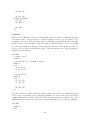
8
Additionally, MARS has an object-oriented architecture, which makes it possible to add
new capabilities in an efficient and systematic fashion. All entities in MARS are organized
in a hierarchical framework. Classes of simple entities, such as edges and faces, are used
to derive more complex entities, such as beams and shells. Since February 2011, MARS
incorporates an interface which makes it possible for users to develop custom objects,
element formulations, and lists. A user can derive new classes from existing ones and
then modify them by inserting new features. For example, a Cosserat 10 node tetrahedral
element was recently developed by a student starting from the already available 10-node
tetrahedral element. The interface is very flexible and allows to incorporate any number
of new objects (material models, special load histories, etc.) and lists (lists typically
implement element formulations, interaction mechanisms, etc.).
MARS has been successfully adopted for the simulation of a wide variety of problems,
which include:
• Modeling of cracking and failure of cement-based materials materials
• Response of reinforced concrete structures to blast loads and fragment impacts
• Cable dynamics problems
• Fragmentation of ordinance casings
• Laceration of plates and shells
1.1
The Lattice Discrete Particle Model (LDPM)
The Lattice Discrete Particle Model (LDPM), is a discrete meso-mechanical model for
concrete, which was recently developed by Dr. Cusatis and co-workers at Rensselaer in
collaboration with Dr. Pelessone at ES3. LDPM simulates the mesostructure of concrete
by a three-dimensional assemblage of discrete particles whose position within the volume
of interest is generated randomly according to the given aggregate size distribution. A
whole section of this report is dedicated to LDPM.
LDPM has been extensively calibrated and validated in the last few years and it has
shown superior capabilities in reproducing and predicting qualitative and quantitative
concrete behavior under a wide range of loading conditions.
1.2
Fragmentation of Weapon Casings
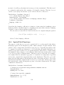
The MARS fragmentation algorithm for solids inserts discrete cracks within a hexahedral
mesh treating failure at the structural level rather than in the material constitutive
equations. The initial mesh is subdivided into clusters of elements. Cracks may form
between clusters when a local measure of damage exceeds a local allowable. Cracks can
propagate and/or coalesce forming fragments of various shapes and sizes. The parameters
of the algorithm have been calibrated for specific weapons so that generated fragment
distributions match arena test data. data.
9
1.3
Nano-Scale Modeling of C-S-H
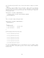
The discrete element capabilities of MARS were used to simulate the behavior of CalciumSilicate-Hydrate (C-S-H) through nano-scale models of C-S-H specimens subjected to
nano-indentation testing. The simulation results from these models are providing new
knowledge in the nanomechanical behavior of C-S-H and are helping in formulating constitutive laws for higher scale simulations. simulations.
1.4
Parallelization
The MARS software can solve extremely large analytical models, which require extensive
use of computer resources. The large demand on computer memory and CPU time
can only be satisfied by using distributed-memory massively parallel computer systems,
like the ones available at the ERDC supercomputer center. Over the last two years
(2008-2010), MARS has been modified to implement domain decomposition and use the
Message Passing Interface (MPI) protocol. This is an on-going area of research, which
puts MARS at the leading edge of simulation software.
1.5
Vehicle Response to Blast
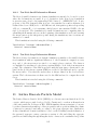
Conversion filters in MARS translate models developed for other codes. In the example below, the model of a Ford Taurus, developed at GWU for crash simulations, was
employed to simulate the effect of surface charges applied on the vehicle.
1.6
Laceration of Plates and Shells
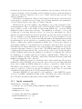
The MARS laceration algorithm is essentially a two-dimensional version of the solid
fragmentation algorithm presented earlier. Cracks can develop between clusters of shell
elements depending on specified local failure criteria. Cracks can propagate or coalesce
to form tears. All material is fully accounted for as all mass is maintained and balanced.
1.7
Steel Plates Structures
Complex steel plate structures commonly found in civil and mechanical construction can
be modeled in great detail with MARS. Contact conditions between all entities in the
model ensure that plates do not penetrate each other. Rivet, bolt, or weld elements are
used to hold plates and braces together.
2
Available Documentation
The MARS documentation consists of four different forms of documentation:
• An online manual hosted at http://www.es3inc.com/mechanics/MARS/Online/MarsManual.htm.
This contains several examples with figures. However, since it is hosted at a remote web-site, that makes it difficult to keep it syncronized with the latest version
10
of MARS. As such, its use is more for general reference but not for specific instructions on how to use input commands.
• A blog hosted at http://es3-mars.blogspot.com/ . This is useful for providing a
chronology of when new features are inserted in MARS.
• A built-in manual printed to an ASCII text file directly from the Mars executable.
The information in the manual is consistent with the features built into the code.
Indeed, it is relatively simple to update the documentation at the same time a new
feature is added or and existing feature is modified, since documentation coexists
in the same source files where the algorithms are implemented. implemented.
MARS is a fast developing solver, with new features being added on a regular basis and
occasional reorganization of existing material. As such, the built-in ASCII manual was
playing a critical role in providing updated documentation consistent with the version of
the program from which it was printed. However, the format of the documentation was
not practical, since it did not provide an updatable table of contents. Furthermore, it
could only be explored using a text editor like vi or Notepad, which provide the basic
’find’ tools for searching specific words inside a file. In February 2011, we realized that
we could restructure the built-in manual and generate better quality documentation.
Essentially, using the polymorphic properties of Object Oriented C-classes, we created
three classes that would process the same information and generate three different types
of documents:
• The ordinary ASCII text manual already available, obtained by executing Mars
with the -H option ( mars -H ). Note that the name of the Mars executable may
vary on different computer systems. Check section on computing platforms.
• An ASCII tex file which can be processed using LaTex for generating a pdf file with
a hyperlinked table of contents. The LaTex file is generated using the -Dl option
where l is the lower case letter l.
• A set of html files which can be accessed using any internet browser. Table of
contents and hyperlinks are also available. These html files are generated in the
current folder using the command mars -Dh. The files can be accessed with any
web browser.
3
Code Architecture and Input Format
The MARS input decks consists of a sequence of blocks, called sections. Each section
specifies the input for an entity, (e.g. material, load curve, etc.) or a list (finite elements
of a component, external faces of a component, contact conditions, etc.). A special
block referenced as ControlParameters includes run control commands and miscellanea
information. The order in which these blocks of information appear in the MARS input
deck provides some flexibility. The ControlParameter section must always be placed at
the beginning of the input because it contains units selections. The definition of new
11
entities must be done before they are referenced in other parts of the input file. In this
manual, we use the term ’entity’ for individual objects, such as material models, reference
systems, load curves, etc., and lists of objects, such as finite element lists, contact lists,
constraint lists, etc.
Each entity is given a descriptive short name which is used as identifier in the rest
of the input file and during post-processing. Similar entities must use unique names.
However, the program does not preclude using the same name for dissimilar entities. For
example, the list of external faces of a list of solid elements (solid component)can be
given the same name as the name of the solid list. This is because a face list and a solid
list are dissimilar.
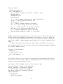
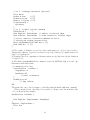
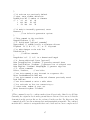
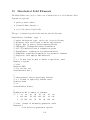
A typical input file looks like this:
First line is always a title line
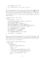
ControlParameters {
. . .
}
Material Steel Elastic {
. . .
}
NodeList PartNodes {
. . .
}
// Finite element definition
HexSolidList PartElements FBSingleIP {
Material Steel
Nodelist PartNodes
. . .
}
// Applied loads
LoadCurve NodalLoad {
. . .
}
NodalLoadList Loads {
Nodelist PartNodes
LoadCurve NodalLoad
. . .
}
// Post-processing
TimeHistoryList History {
. . .
}
PlotList Plot {
. . .
}
EOF
12
3.1
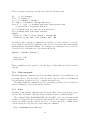
Major Syntax Rules
The current MARS format adopts a syntax style which resembles the C++/Java styles
with long descriptive keywords. Comments can be entered using the // characters at
any place in a line (similar to the Fortran exclamation mark). Entire sections can be
commented out using the ’/*’ sequence at the beginning and the ’*/’ sequence at the
end. The C++ based syntax style makes it possible to take advantage of the vim (vi
modified editor) syntax checker available on most Unix-based systems, including Linux.
The vim syntax checkers paints words in a text file with different colors to differentiate
number, comments, keywords, etc. The MARS syntax checker file is based on the C++
file with some modifications. modifications.
Each block of data is limited by curly brackets, as shown in the previous example.
Within each block, there may be sub-blocks of data which are also contained in curly
brakets. For example:
HexSolidList SolidPart FBSingleIP {
NodeList Nodes
EditNodeList {
Move 2. in 0. in 0. in
}
}
The commands inside these blocks are intended to be indented, with the number of spaces
proportional to the level of indentation. Although MARS does not enforce indentation,
it is good practise to consistently indent an input file; for example, indent by two spaces
for each level of indentation. Indentation makes the input more readable.
3.2
The Solver Loop
The solver loop performs a sequence of tasks.
A summerized version of the solver loop is listed below. This is specially useful for
those who intend to write user-defined objects and lists
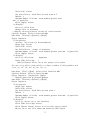
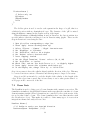
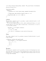
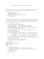
while (time < terminationTime) {
// update MPI domains (if necessary)
mpiDomains.update();
// reset nodal forces and moments to zero
for (jL = 0; jL < numLists; jL++)
list[jL]->clearNodalForces();
// compute nodal internal forces - apply external forces
for (jL = 0; jL < numLists; jL++)
list[jL]->calcFrc();
// write time history output (if necessary)
for (jL = 0; jL < numLists; jL++)
list[jL]->writeTimHistRecord();
// reduce forces for master-slave formulations
13
// (node: loop uses inverse list order)
for (jL = (numList-1); jL > -1; jL--)
list[jL]->reduceFrc();
// apply constraints
for (jL = 0; jL < numLists; jL++)
list[jL]->applyConstraints();
// write 3-D plot file records (if necessary)
for (jL = 0; jL < numLists; jL++)
list[jL]->writePlotFile();
// perform tasks from the action list
for (j = 0; j < numActions; j++)
action[j]->exec();
// integrate equations of motion
for (jL = 0; jL < numLists; jL++)
list[jL]->integrateEOM();
// apply kinematic conditions for master-slave formulations
for (jL = 0; jL < numLists; jL++)
list[jL]->applyKin();
// update time parameters
time += dt1;
numSteps++;
// go interactive if requested
checkSignal();
}
4
Control Parameters
The ControlParameters section follows the title line and is used for defining parameters
that control the simulation or global parameters. The first command must always be the
selection of units. A detail description of units is give in a separate subsection.
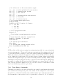
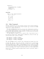
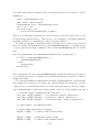
ControlParameters {
// Unit specification should be the first input line
Units English // more on this below
TerminationTime 1. ms
CurrentTime 0.1 ms
MaximumTimeStep 0.001 ms
TimeStepScalingFactor 0.8 // default 0.9
FragmentationTimeInterval 0.005 ms
/ time or step cotrolled actions
Monitor Frequency 10 // print progress line every 10 steps
// more on this below
PlottingDefaults { ... } // see below
ContactDefaults { ... } // see below
14
DynamicRelaxationCurve DynRelax
NoDynamicRelaxation // stop dyn relax on restart
}
4.1
Unit Systems
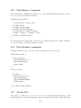
The unit system to be employed in a simulation is specified using the command Units
followed by one of the unit system label: SI / CGS / English / Nano.
1. SI: international, m, Kg, second
2. CGS: cm, gram, second
3. English: in, pound, second
4. Nano: nm, ng, ns
The unit system can be specified once, typically at the top of the ControlParameters
section. All input quantities are converted to the selected unit system. For this reason,
all quantities must be entered with their dimensional units. For example, if SI units are
chosen and the user enters a time variable of 0.1 ms, this variable will be automatically
converted to 0.0001 (s). This can be very useful for material properties; for example, the
density of a material can be found in g/cm3 and it would be tricky for most analysts
to convert it to the correct dimensions in English units. A list of available dimensional
units is given in the next subsection.
4.1.1
Dimensional Units
Below is a list of implemented dimensional units and physical quantitities which are
typically used for specifying input parameters of MARS structural models. This list
is often updated with new quantitities and units depending on what new features are
inserted in MARS. If the wrong units are used for an input parameter, MARS errors off
and prints the available units from the list below.
The conventions described in ”The Unified Code for Units of Measure” are employed.
For SI and CGS systems, kilo (x 1,000) is denoted with the lower letter ’k’ as in kg or
km, Mega (x 1,000,000) with ’M’, giga (x 1.e9) with ’G’, milli (x 0.001) with ’m’, micro
(x 1.e-6) with ’u’, pico (x 1.-9) with ’p’.
Quantity: Nondimensional
Reference unit: unit (no label necessary)
%:(0.01)
Quantity: Time
Reference unit: s
ms:(0.001) - micros:(1e-06) - s:(1e-06) - us:(1e-06) - ns:(1e-09) - mcs:(1e-06)
15
Quantity: Length
Reference unit: m
cm:(0.01) - mm:(0.001) - km:(1000) - in:(0.0254) - ft:(0.3048) - km:(1000) - nm:(1e-09)
- mcm:(1e-06) - um:(1e-06)
Quantity: Area
Reference unit: m2
cm2:(0.0001) - mm2:(1e-06) - km2:(1e+06) - in2:(0.00064516) - ft2:(0.092903) - Km2:(1e+06)
- nm2:(1e-18)
Quantity: Volume
Reference unit: m3
cm3:(1e-06) - mm3:(1e-09) - km3:(1e+09) - in3:(1.63871e-05) - ft3:(0.0283168) - km3:(1e+09)
- nm3:(1e-27) - Km3:(1e+09)
Quantity: Mass
Reference unit: Kg
g:(0.001) - lb:(0.453592) - lb.s2/in:(175.127) - lb-s2/in:(175.127) - kg:(1) - ng:(1e-12)
- nnKg:(1e-18) - mcg:(1e-09) - mg:(1e-06) - ug:(1e-09)
Quantity: Density
Reference unit: Kg/m3
g/cm3:(1000) - lb/in3:(27679.9) - lb.s2/in4:(1.06869e+07) - lb-s2/in4:(1.06869e+07)
- lb/ft3:(16.0185) - kg/m3:(1) - nnKg/nm3:(1e+09)
Quantity: Velocity
Reference unit: m/s
cm/s:(0.01) - mm/s:(0.001) - Km/s:(1000) - in/s:(0.0254) - ft/s:(0.3048) - km/s:(1000)
- nm/ns:(1) - Km/hr:(0.277778) - mph:(0.44704) - Knots:(0.514444)
Quantity: Force
Reference unit: N
dyn:(1e-05) - lb:(4.44822) - lbf:(4.44822) - kip:(4448.22) - nN:(1e-09)
Quantity: Pressure
Reference unit: Pa
psi:(6894.76) - ksi:(6.89476e+06) - lb-in-s:(6894.76) - MPa:(1e+06) - GPa:(1e+09) dyn/cm2:(0.1) - nPa:(1e-09)
16
Quantity: Stress
Reference unit: Pa
psi:(6894.76) - ksi:(6.89476e+06) - lb-in-s:(6894.76) - MPa:(1e+06) - GPa:(1e+09) dyn/cm2:(0.1) - nPa:(1e-09)
Quantity: Energy
Reference unit: J
erg:(1e-07) - ft-lbf:(1.356) - in-lbf:(0.113) - nJ:(1e-09) - nnJ:(1e-18)
Quantity: Stiffness
Reference unit: N/m
J/m2:(1) - dyn/cm:(0.001) - erg/cm2:(0.001) - lbf/in:(175.127) - nN/nm:(1)
Quantity: Rate
Reference unit: 1/s
1/ms:(1000) - 1/ns:(1e+09) - Hz:(1)
Quantity: Angle
Reference unit: deg
rad:(0.0174533)
Quantity: Momentum
Reference unit: Kg-m/s
Kg.m/s:(1) - g-cm/s:(1e-05) - g.cm/s:(1e-05) - lb-in/s:(0.0115212) - kg-m/s:(1) - kg.m/s:(1)
Quantity: RotationRate
Reference unit: rad/s
deg/s:(0.0174533) - rpm:(0.10472) - rps:(6.28319) - rad/ns:(1e+09)
Quantity: Moment
Reference unit: N-m
dyn-cm:(1e-07) - lb-in:(0.112985) - lbf-in:(0.112985) - kip-in:(112.985) - nN-nm:(1e18)
Quantity: Acceleration
Reference unit: m/s2
cm/s2:(0.01) - mm/s2:(0.001) - nm/ns2:(1e+09) - in/s2:(0.0254) - ft/s2:(0.3048)
17
Quantity: EnergyDensity
Reference unit: J/m3
erg/cm3:(0.1) - lbf/ft2:(47.8867) - lbf/in2:(6895.68) - nJ/nm3:(1) - nnJ/nm3:(1e-09)
Quantity: Power
Reference unit: W
kW:(1000) - MW:(1e+06) - erg/s:(1e-07) - hp:(745.7) - ft-lbf/s:(1.356) - in-lbf/s:(0.113)
Quantity: PowerDensity
Reference unit: W/m3
kW/m3:(1000) - MW/m3:(1e+06) - erg/s-cm3:(0.1) - hp/m3:(745.7) - lbf/s-ft2:(47.8867)
- lbf/s-in2:(6895.68)
Quantity: Temperature
Reference unit: degK
degC:(1) - degR:(1.8) - degF:(1.8)
Quantity: TemperatureRate
Reference unit: degK/s
degC/s:(1) - degR/s:(1.8) - degF/s:(1.8)
Quantity: TemperatureInvrs
Reference unit: 1/degK
1/degC:(1) - 1/degR:(0.555556) - 1/degF:(0.555556)
4.2
Actions
These commands are used to schedule various types of tasks to be performed at specific
times or steps during the simulation. Each command is entered in a single line of input.
These commands are contained in the ControlParameter input block.
ControlParameters {
. . .
FlushTHFiles Every 0.1 ms
GoInteractive AtTime 10. ms
WriteRestartFile Every 0.1 ms
. . .
}
18
4.2.1
Go Interactive
These commands are used to schedule when the program should go interactive. This
command is not executed for batch runs.
GoInteractive
GoInteractive
GoInteractive
GoInteractive
4.2.2
AtTime 10. ms
AtStep 10000
Every 0.1 ms
IfTimeStepLessThan 0.0001 ms
Print Progress Line
These commands are used to schedule the printing of a line to the output file. More that
one command can be used.
PrintProgressLine Frequency 1
PrintProgressLine Frequency 10 Value vmx
// Values can be vmx, ken (default), fmx, wrk
4.2.3
Write Restart File
These commands are used to control the frequency for writing restart files. More that
one command can be be used.
WriteRestartFile AtTime 10. ms
WriteRestartFile AtStep 10000
WriteRestartFile Every 0.1 ms
4.2.4
Execute Function
These commands are used to schedule the execution of a macro function. More that one
command can be used.
ExecFunction
ExecFunction
ExecFunction
ExecFunction
4.2.5
’FunctionName’
’FunctionName’
’FunctionName’
’FunctionName’
AtTime 10. ms
AtStep 10000
Every 0.1 ms
IfTimeStepLessThan 0.0001 ms
Flush Time Hist Files
These commands are used to schedule when to flush the buffers of the time history
datafiles.
FlushTHFiles AtTime 10. ms
FlushTHFiles AtStep 10000
FlushTHFiles Every 0.1 ms
19
4.2.6
Read Input File
These command is used to schedule a reading event. At the requestest time or step,
MARS will read an input file which contains regular input commands. The input file
may be used to add parts to the model, make modifications to the model, write output
files, etc.
Read ’FileName’ atTime 10. ms
Read ’FileName’ atStep 10000
4.2.7
Write Plot DataFile
These commands are used to schedule when to write database snapshots to the plot data
file for later post-processing.
WritePlotDatFile data.plt Every 0.1 ms
More detail on this procedure are given in the HowTo section.
4.2.8
ExecImplicitSolver
Either command is used for executing the implicit solver at step 0 or at time 0. seconds:
ExecImplicitSolver ’solverName’ atStep 0
ExecImplicitSolver ’solverName’ atTime 0. s
4.3
Time Step Control
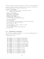
The time step used in the MARS explicit time integration scheme can be controlled
for both stability and accuracy and is determined by the procedure described in this
section. First, MARS computes a Courants time step for each list. This time step is
based on the smallest time step for each element in a list. When multiple mechanisms
come into play simultaneously, such as contact conditions, penalty constraints, etc, the
added stiffness may require for the calculated time step to be further reduced. In general,
it is good practice to reduce the time step when a simulation goes unstable. Very often,
this is caused by overlapping effects. If this action does not solve the instability, then the
instability may be caused by some other reason, such as poor algorithm, possible bug,
etc. and the user should notify the developer.
MARS uses the following procedure to determine the time step used in the explicit
time integration scheme. First the Courants stability limit Dtc is determined list by list
and the minimum is selected. The Courants time step is then multiplied by a scaling
factor s defined via input (default value for s is 0.9). The reduced time step is compared
to a maximum allowable time step Dtmax prescribed via input; the minimum of the two
is chosen. chosen.
Dt* = s * Dtc
Dt = min (Dt*, Dtmax)
20
The maximum time step Dtmax can be defined either as a constant throughout the simulation or as a function of time. The second method is useful when we want the simulation
to start with a very small step (for accuracy and not stability like in an impact problem)
and then relax this condition as the simulation progresses. progresses.
For constant maximum time step the commands are:
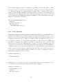
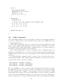
ControlParameters {
Units English
TimeStepScalingFactor 0.7
MaximumTimeStep 0.001 ms
. . .
}
For time dependent maximum time step the commands are:
ControlParameters {
Units English
. . .
}
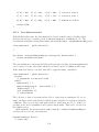
LoadCurve MaxStepHist {
// Max allowed time step starts with Dt = 0.1 microsec and grows
// linearly to 1 microsec in the first ms of the simulation,
// it remains constant thereafter
X-Units time ms
Y-Units time ms
ReadPairs 3
0.0
0.0001
1.0
0.0010
10.0
0.0010
}
ControlParameters {
MaximumTimeStepHistory MaxStepHist
}
4.4
Plotting Defaults
Plotting defaults are used for initializing the attributes of plottable lists.
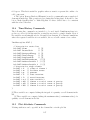
PlottingDefaults {
TimeInterval 0.1 ms [1]
DisplacementScalingFactor 1000 // [2]
X-DisplacementScalingFactor 1000 // [2]
Y-DisplacementScalingFactor 1000 // [2]
Z-DisplacementScalingFactor 1000 // [2]
ThickShells
BinaryPlotFiles
}
21
[1] This command is used for setting a default time interval for all plot lists. This
value can be overwritten inside a PlotList input section
[2] These commands are used to magnify displacements. In most large deformation
problems, displacement magnification will produce meshes that are too distorted. It can
be useful for small deformation problems, like the fracturing of concrete specimens under
quasi-static loadings.
4.5
Contact Defaults
Contact defaults are used for initializing some parameters in the contact lists. Currently, only the detection distance parameter and the node/edge/face thicknesses can be
specified. The syntax is shown below.
ContactDefaults {
UpdateInterval 0.1 ms // Discontinued (Apr 2011)
DetectionDistance 0.2 cm
StaticFriction 0.3 // Discontinued (Apr 2011)
DynamicFriction 0.2 // Discontinued (Apr 2011)
NodeThickness 0.1 in
EdgeThickness 0.2 in
FaceThickness 0.1 in
}
4.6
Global Updates
This command has been added in June 2011. It is meant to replace the updates specified
in some lists, such as contact lists, mpi-domain list, etc. The reason for this change is that
updates must be synchronized. For example, a contact update and a MPI domain decomposition update must be done at the same time. For this reason, the UpdateInterval
command in the contact lists will be discontinued.
ControlParameters {
. . .
GlobalUpdateTimeInterval 0.1 ms
}
4.7
Dynamic Relaxation
Dynamic relaxation is a numerical technique that uses an artificial form of damping to
dissipate kinetic energy and converge to a steady state equilibrated solution if possible.
Dynamic relaxation can be used to compute steady-state stress under static loading
conditions in a system before a dynamic load is applied, or find a stable configuration
after a dynamic load has been applied. In dynamic relaxation, nodal velocities of all nodes
are scaled by a factor slightly less than one. There have been studies that show how to
optimize the scaling factor depending on the lowest natural frequency of the system. In
22
general, if the scaling factor is too small, the simulation overshoots the static solution,
possibly resulting in excessive plastic deformations or damage. If the scaling factor is too
large (closer to 1.), the convergence rate becomes very slow. There is no magic formula
for choosing the optimal scaling factor; the user has to develop a ’feel’ for what works best
using intuition and a trial-and-error process.In some codes, the scaling factor is specified
via input and remains constant throughout the simulation. One disadvantage of this
approach is that the damping rate varies with the integration time step. In MARS, the
scaling factor is computed as to achieve a desired velocity reduction per unit time (1.
microsecond). To make the approach more flexible, the relaxation profile is defined as
a function of time in a ’LoadCurve’ object. Since the variables of a load curve require
dimensional units, the dynamic relaxation command must be specified father down in
the input stream, as shown in this example. example.
ControlParameters {
Units English
. . .
}
. . .
LoadCurve DynRelax {
X-units time ms
Y-units nondimensional
// dyn relax operates in the first ms
// with velocity reduction of 1% per microsec
ReadPairs 4
0.000
0.01
1.000
0.01
1.001
0.00
10.000
0.00
}
ControlParameters {
...
DynamicRelaxationCurve DynRelax // dynamic relaxation
}
To stop dynamic relaxation on restart use
ControlParameters {
. . .
NoDynamicRelaxation
}
4.8
Gravity
Gravity loads are automatically computed by specifying a gravity acceleraction. The
command can be placed anywhere in the input file after the ControlParameters section.
23
The direction of the acceleration can be prescribed either using one of the three axis
labels (’X’, ’Y’, or ’Z’) or more generically using the cosines of a generic direction.
ControlParameters {
. . .
Gravity -9.8 m/s2 Z
// or
Gravity 9.8 m/s2 Direction 0. 0. -1.
}
It is possible to apply the gravity load progressively in time using a time history profile.
The time history profiles is specified via a load curve, in the same fashion of how it is done
for dynamic relaxation. The load curve provides a scaling factor which is multiplied by
the value of the acceleration specified after the keyword Gravity. In the example below,
the gravity is linearly increased from 0 to its final value of 9.8 m/s2 in 2 milliseconds and
then it is kept constant.
ControlParameters {
Units English
. . .
}
. . .
LoadCurve GravityHist {
X-units time ms
Y-units nondimensional
ReadPairs 3
0.
0.00
2.
1.00
100.
1.00
}
ControlParameters {
...
Gravity 9.8 m/s2 Direction 0. 0. -1.
}
4.9
History GravityHist
Plugins
By plug-ins, we mean other codes that can be executed from MARS and perform specific
tasks. Currently, there are four plug-ins:
• Quasar: for displaying 3-d models
• Xth: for displaying time history plots
• triangle: for generating triangular meshes
• tetgen: for generating tetrahedral meshes
24
5
Miscellanous Objects
5.1
Reference Systems
Reference systems are used for two main purposes:
1. When generating parts, they are used for aligning a new part in the desired orientation.
2. In finite element formulations, they are used for aligning the local element axis and
computing internal strains and stresses.
Three reference systems are available:
1. cartesian,
2. cylindrical, and
3. spherical.
Some applications require the reference system to return a preferential direction, which
is used for aligning the first local axis; use the keyword ’return’ to select the preferential
axis.
5.1.1
Cartesian RefSys
ReferenceSystem RSYS cartesian {
// 1. Define origin (Opt., default = 0, 0, 0)
Origin 0.2 in 0.6 in 0. in
// 2. Define orientation (Req.)
FirstDirection 1. 0. 0.
SecondDirection 0. 1. 0.
// 3. Modify (Opt.)
Translate 0.4 in 0.3 in 0.6 in
X-Rotate 45
// 4. Select ’Return’ direction
Return X
// also available Y, and Z
}
5.1.2
Cylindrical RefSys
ReferenceSystem RSYS cylindrical {
// 1. Define origin (Opt., default = 0, 0, 0)
Origin 0.2 in 0.6 in 0. in
// 2. Define orientation (Req.)
AxialDirection 1. 0. 0.
25
RadialDirection 0. 1. 0.
// 3. Modify (Opt.)
Translate 0.4 in 0.3 in 0.6 in
X-Rotate 15 deg
Y-Rotate 35 deg
Z-Rotate 180 deg
// 4. Select ’Return’ direction
Return HoopDirection // for shells and solids
}
5.1.3
Spherical RefSys
ReferenceSystem RSYS spherical {
// 1. Define origin (Opt., default = 0, 0, 0)
Origin 0.2 in 0.6 in 0. in
// 2. Define orientation (Req.)
AxialDirection 1. 0. 0.
RadialDirection 0. 1. 0.
// 3. Modify (Opt.)
Translate 0.4 in 0.3 in 0.6 in
X-Rotate 15 deg
Y-Rotate 35 deg
Z-Rotate 180 deg
// 4. Select ’Return’ direction
Return HoopDirection // for shells and solids
// also available AxialDirection, RadialDirection
}
5.2
Load Curves
The LoadCurve object is used to prescribe a function of the type y = f (x) in tabulated
form by entering (xi , yi ) pairs. These tabulated functions are used in many algorithms.
If during interpolation, the value of x falls outside of the definition range, the value of
y is not extrapolated. Instead, it is set to the first or last value in the table. The input
data pairs must be in ascending order of x .
LoadCurve ’CurveName’ {
// 1. Specify units (Req.)
X-units time ms
Y-units pressure psi
// 2. Enter tabulated function (Req.)
ReadPairs 4
// tim
prss
0.000
0.
0.005
100.
26
0.030
0.
1.000
0.
// 3. Modify function (Opt.)
// the following commands are optional
X-Scale 2. // scale x-variable
X-Offset 0.004 // offset x-variable
Y-Scale 2. // scale y-variable
Y-Offset 0.004 // offset y-variable
Differentiate // differentiate curve [1]
}
zi = (yi+1 − yi − 1)/(xi+1 − xi−1 )
[1] The Differentiate command is used to compute a function which is the differential of the input function
Some common functions can be internally generated in tabulated form. The available
functions are listed below: below:
LoadCurve ’CurveName’ {
// 1. Specify units (Req.)
X-units time ms
Y-units pressure psi
// 2. Generate internal function
// yi = 5. sin(45 xi) for xi = i*0.1
Generate Sin { A 5. w 45. dt 0.1 n 100
// yi = 5. cos(45 xi) for xi = i*0.1
Generate Cos { A 5. w 45. dt 0.1 n 100
}
and i=0,100
}
and i=0,100
}
In time history lists, the current value of a time dependent function can be printed using
the command lc-’curveName as shown below
TimeHistoryList ... {
. . .
lc-’curveName’
}
5.2.1
Load Curves Lists
It is possible to group a set of load curves that share similar characteristics in a list of
load curves (see specific topic in the Misc. section of this manul.) This is the case for
reading pressure histories generated by a fluid code.
5.3
Built-In Blast Loads
The built-in blast loads consists of a series of objects that are used in face lists (triangular
and quadrilateral faces) for generating pressure loads. Typically, these loads are used
for approximating the effects of blast. Pressures are computed taking into account the
location of the explosion and the position and orientation of the exposed faces.
27
5.3.1
ConWep
ConWep is a collection of conventional weapons effects calculations from the equations
and curves of TM 5-855-1, ’Design and Analysis of Hardened Structures to Conventional
Weapons Effects.’ ConWep performs a variety of conventional weapons effects calculations including an assortment of airblast routines, fragment and projectile penetrations,
breach, cratering, and ground shock. shock.
The equations used in this special load object are based on a report by Kingery, C.N.,
and Bulmash, G. ’Airblast Parameters from TNT Spherical Air Burst and Hemispherical
Surface Burst’, Technical Report ARBRL-TR-02555, U.S. Army ARDC-BRL, Aberdeen
Proving Ground, MD, April 1984, and other reports as follows:
1) The following methods are based on the equations from BRL Technical Report
ARBRL-TR-02555 for predicting positive phase parameters for either a hemispherical
surface burst or spherical free air burst:
bool
real
real
real
real
real
real
real
real
real
real
equationsAreNotValid();
peakIncidentPressure();
// [psi]
incidentImpulse();
// [psi-ms]
normallyReflectedPressure(); // [psi]
normallyReflectedImpulse(); // [psi-ms]
timeOfArrival(); // time of arrival of blast wave [ms]
duration();
// time positive phase is done [ms]
shockFrontVelocity();
// [ft/ms]
rfp(real p, char tp); // range for given charge and pres. [ft]
rfi(real i, char ti); // range for given charge and imp. [ft]
rft(real t, char tt); // range for given charge and time. [ft]
2) The following methods, based on the modified Friedlander wave form, are used to
determine shape factor, pressure history and dynamic pressure history for the positive
phase:
real waveShapeFactor(real imp, real pmx, real dt);
real pressureAtTime(real tau, real pmx, real wsf);
real dynPrssAtTime(real tau, real q, real wsf);
// [psi]
// [psi]
3) Use the AFWL-70-127 curves to determine the following:
real reflectedPressureCoefficient(real alp, real pso);
4) Use the TM 5-1300 procedure (Figure 2-192) to find the following:
real reflectedImpulseAtAnAngle(real alp);
// [psi-ms]
5) Use formula presented by W.E. Baker to determine the following:
real peakDynamicPressure(real pso); // [psi]
28
The input commands for specifying this special load are:
SpecialLoad BRST ConWep {
x0 1. in 20. in 0. in
weight 100 lb
[ hemispherical ]
offset 0.012 ms
}
The ’offset’ parameter is used to offset the time of blast so that the shock wave reaches
the exposed surfaces at time zero of the numerical simulation. To compute the optimal
offset time, execute the first calculation with an offset of 0. Then, look at the output and
it will tell you when the shock wave reaches the surface. Use that value to offset the blast.
This operation is done manually because if multiple explosions had to be performed in
the same simulation, the user must have the ability to control the relative offset.
5.4
Random Number Distributions
The random number generation object generates random numbers using one of the common distributions equations. Currently, four distributions are available. Random number
generators are used for the definition of some inputs. In most cases, the user can select
which distribution to use, since they are interchangable.
5.4.1
Weibull distribution
The Weibull distribution has been used very effectivley for characterizing probabilistic
failure in materials and mechanical components. The probability density function is
defined as
g x−m
P (x) =
a
a
(g−1)
x−m
exp −
a
g for x > m,
where where
m: location parameter mu
a: scale parameter alpha
g: shape parameter gamma
The cumulative distribution function is defined as
x−m
F (x) = 1 − exp −
a
g The input command is given by
Weibull { m 0.4 a 1. g 2 [ n ] }
where the optional ’n’ is used to normalize the distribution.
29
= 0 otherwise
5.4.2
Uniform distribution
Uniform { d 0.2 }
numbers are generated evenly between 1-d/2 and 1+d/2
5.4.3
Gaussian distribution
The Gaussian distribution or normal distribution is a common ’bell shaped’ distribution.
The probability density function is defined as
PDF(x) = 1/sqrt(2*PI*s^2) exp[-(x-m)^2/2*s^2]
where
s: standard deviation
m: mean
MARS generates random numbers which are consistent with a Gaussian distribution
using the Box-Muller transformation. The Box-Muller Transformation (polar form) generates a pair of random numbers which have a Gaussian distribution with a zero mean
and a standard deviation of one. See See
http://www.taygeta.com/random/gaussian.html
The input command is
Gaussian { s 2. m 0.3
where
mn: is a lower limit
mx: is un upper limit
mn 0. mx 4. }
In other words, random numbers less than ’mn’ or larger than ’mx’ are rejected. ’mn’
and ’mx’ are optional inputs.
5.4.4
Fuller distribution
The Fuller/Thompson equation is defined as
P
where
P
d
u
c
= (d/u)^c
=
=
=
=
percent finer than the sieve
aggregate size being considered
maximum aggregate size to be used
parameter which adjusts curve for fineness or coarseness
Fuller { c 0.5 l 0.4 cm u 1.2 cm [x] }
// c: fuller coefficient
// l: lower value
// u: upper value
// x: examine
30
The distribution is defined in the range of aggregate size between ’l’ and ’u’, where
’l’ is the minimum aggregate size being considered. For maximum particle density, ’c’
is approximately 0.5 according to Fuller and Thompson. In the example above, if we
consider an aggregate size of 0.8 cm, then P = (0.8/1.2)0.5 = 81% of aggregates are
smaller than 0.8 cm. For details, see this web site:
http://training.ce.washington.edu/wsdot/modules/03 materials/03-2 body.htm
5.5
Colors
Colors are used in the definition of surfaces and lines. There are two methods for specifying colors. The first by selecting a color from the built-in list using the command
Color Red
Available colors are: Red, Green, Blue, Darkgray, Lightgray, Black, Cyan, Steel,
Rust, White, Yellow, Orange, Gold, Patina, Clear. The other, by specifying the rgb
composition using the command
Color rgb 0.4 0.6 0.2
where the three numbers following the ’rgb’ keyword indicate the brightness of each
color (red, green, blue in this order) on a scale from 0 to 1.
5.6
Strain Gages
The StrainGage object is designed to simulate the behavior of actual strain gages. As
such, it can provide a more realistic measurement of local deformations for comparison
with test data than the various strain metrics from continuum mechanics. The strain
gage object is defined by selecting two or more material points inside or on the surface
of a part. The points are placed in correspondence of where the physical strain gage
is placed. While physical strain gage are only placed on the surface of a part, these
numerical strain gage can be also placed in the interior of a part. The numerical strain
gage is defined using its location, length, and direction.
The main purpose of the numerical strain gage is to produce a time history record
of the local strain which can be used for comparison with test data or just for better
understanding of the results from the simulation. The numerical strain gage computes
the a total length by summing the lengths of the segment[s] used in the definition. The
length L0 at time 0 is assumed to be the reference length at rest of the strain gage. The
linear strain eps(t) at time t is defined as eps(t) = (L(t)/L0) - 1, where L(t) is the strain
gage length at time t. The logarithmic strain is defined as eps(t) = ln(L(t)/L0).
The structure of a typical strain gage input is shown below.
StrainGage ’GageName’ {
// part on which the strain gage is attached to
// type dependent parameters
. . .
}
More details on how to place strain gages on various types of meshes are discussed in the
subsections below.
31
5.6.1
Strain-Gage for hexahedral solid lists
Currently, strain gages can only be placed on the surface of a hex solid element mesh.
Typical input is shown below:
StrainGage GageX {
hxL ’HexPartName’ // or HexSolidList ’HexPartName’
Description Strain gage at location X5
CenterAt 0. cm 10. cm 9. cm
Length 2. cm
Segments 3
Direction 0. 1. 0.
}
5.6.2
Strain-Gage for tetrahedral solid lists
Strain gages can only be placed on the surface or in the interior of a tet solid element
mesh. Typical input is shown below:
StrainGage GageX {
TetSolidList Solid
Description Strain gage at location X5
CenterAt 0. cm 0. cm 0. cm
Length 2. cm
Segments 3
Direction 0. 1. 0.
}
5.6.3
Strain-Gage for quadrilateral shell lists
Strain gages can be placed on the top surface, bottom surface, or mid-plane (membrane
strains) of a quadirlateral shell element mesh. Typical input is shown below:
StrainGage SGx {
qsL ’ShellPartName’ // or QuadShellList ’ShellPartName’
Description Strain gage at location X5
CenterAt 0. cm 10. cm 9. cm
TopSurface // also ’BottomSurface’ [1]
Length 2. cm
Segments 3
Direction 0. 1. 0.
}
[1] If neither TopSurface or BottomSurface keyword is specified, then the default is
mid-plane surface for computing membrane strains.
32
5.6.4
TimeHistories
The strain gage computes a single variable: the total strain at the prescriped point over
a prescribed length. The only purpose of a StrainGage is to provide a measurement of
local strain for time history lists. Typical application show up as
StrainGage Gage1 {
. . .
}
. . .
TimeHistoryList HIST {
. . .
sg-Gage1 linear S 1000. //
}
’linear’ or ’logarithm’ [1]
[1] The keywords linear and logarithm are used to specify how strains are computed
and it makes a difference mostly for large deformations. Default is linear.
5.7
Accelerometer
The Accelerometer object is designed to simulate the behavior of actual accelerometers
for direct comparisons with acceleration records measured in test setups. The acceleration
computed by the Accelerometer object employs a corotational formulation suitable for
large rotations. As such, it may be different than the acceleration computed at the nodes
in the global fixed reference system. While physical accelerometers are only placed on
the surface of a part, these numerical accelerometers can be also placed in the interior of
a part. The numerical acceleration is defined using its location, length, and direction.
The main purpose of the numerical accelerometer is to produce a time history record
of the local acceleration which can be used for comparison with test data or just for
better understanding of the results from the simulation. Accelerations are computed as
follow
an =
~v (t) − ~v (t − ∆t)
· ~n
∆t
where n is the corotational direction aligned with the accelerometer.
There are two types of numerical accelerometer: 1. Those attached to a finite element
component, 2. Those embedded in a discrete element model (cloud of points).
Typical input is shown below.
Accelerometer ’GageName’ type {
// part on which the strain gage is attached to
// type dependent parameters
. . .
}
More detailed input on how to place an accelerometer on various types of meshes are
discussed in the subsections below.
33
5.7.1
Attached to quadrilateral surfaces
Accelerometer AG01 QuadFace {
FaceList OuterPlate
Description Accelerometer AG-01
CenterAt 0. in 10. in 9. in
Tolerance 0.01 in
Direction 0. 0. 1
}
5.7.2
Attached to triangular surfaces
Accelerometer AG01 TriangFace {
FaceList OuterPlate
Description Accelerometer AG-01
CenterAt 0. in 10. in 9. in
Tolerance 0.01 in
Direction 0. 0. 1
}
5.7.3
Attached to the surfaces of a beam element
Accelerometer AG01 Beam {
BeamList OuterPlate
Description Accelerometer AG-01
CenterAt 0. in 10. in 9. in
Tolerance 0.01 in
Direction 0. 0. 1
}
5.7.4
TimeHistories
The accelerometer computes a single variable: the acceleration component at the prescriped point in the prescribed corotational direction. The only purpose of an Accelerometer
is to provide acceleration for time history lists. Typical application show up as
Accelerometer Gage1 QuadFace {
. . .
}
. . .
TimeHistoryList HIST {
. . .
ac-Gage1
}
34
5.8
Equations
This is a collection of objects that implement global equations, such as pressure-volume
equations, etc.
5.8.1
Pressurized Volume
Equation ’name’ PressurizedVolume {
InitialVolume 34.53 cm3
InjectionHistory ’name2’
// Enter the name of fluid or BulkModulus
Oil / Water / Air
Temperature 70 degF
}
5.8.2
Injected Fluid
Use this equation when ... Work still in progress
LoadCurve ’name2’ {
// Specify flow rate history
. . .
}
Equation ’name’ InjectedFluid {
InitialVolume 34.53 cm3
InjectionHistory ’name2’
// Enter the name of fluid or BulkModulus
Oil (K = 1.5e9 Pa) / Water (K = 2.2e9 Pa) / Air (1.42e5 Pa)
BulkModulus 10e6 psi
}
5.8.3
Adiabatic Compression
This feature was inserted in the code in the spring of 2009. The purpose of this feature
is to enable the numerical simulation of the effect of air trapped inside a cavity whose
volume changes during the simulation. The pressure in the cavity is related to the change
in volume using the adiabatic equation:
p(t)V (t)γ = const
where p(t) is the pressure, V (t) is the volume of the cavity, and γ is the adiabatic
index of the gas. The ability to model these conditions was introduced into the MARS
code through a new C++ class denoted as AdiabaticEquation . This class is derived
from the base class Equation . The ’AdiabaticEquation’ class implements the very simple
adiabatic equation:
p(t) = (V0 /V (t))γ p0
where p0 and V0 are the initial value of the pressure and volume respectively. The
method implemented in Mars actually returns the overpressure, which is defined as
35
po (t) = p(t) − p0
The input block requires three parameters as shown below:
Equation ’name’ AdiabaticCompression {
InitialVolume 34.53 cm3
InitialPressure 14.7 psi
Gamma 1.4
[ InvertSign ]
}
The InvertSign command should be used when the surfaces point toward the cavity
rather than away from it.
5.9
Material Models
5.9.1
Elastic Material Model
The elastic material model implements the simplest forms of constitutive equations in
three main formats: tensorial, plane stress (for shells), and vectorials (for beams).
Material ELST elastic {
Description Stainless Steel ...
Density 7.8 g/cm3
YoungsModulus 29e6 psi
PoissonsRatio 0.3
}
State variables for tensorial equations
1:
2:
3:
4:
5:
6:
XX-Stress
YY-Stress
ZZ-Stress
YZ-Stress
ZX-Stress
XY-Stress
[stress]
[stress]
[stress]
[stress]
[stress]
[stress]
State variables for plane stress equations
1:
2:
3:
4:
5:
XX-Stress
YY-Stress
YZ-Stress
ZX-Stress
XY-Stress
[stress]
[stress]
[stress]
[stress]
[stress]
36
State variables for vectorial equations
1: "Normal stress" [stress]
2: "Shear stress X" [stress]
3: "Shear stress Y" [stress]
5.9.2
Elastio-plastic Material Model
Material PLST plastic {
Description Stainless Steel ...
Density 7.8 g/cm3
YoungsModulus 29e6 psi
PoissonsRatio 0.3
YieldStress 80e3 psi
HardeningModulus 200e3 psi
#-- select one of the three hardening options below
IsotropicHardening
KinematicHardening
Beta 0.5 // beta = 0 istropic, beta = 1 kinematic
hmx 8e3 psi // Bounding stress for friction damping
}
’Friction’ damping provides hysteretical energy loss for each cycle related to cycle amplitude and not strain rate. Because it is non-viscous the term ’friction’ damping is used.
Use a bounding stress in the order of one percent of the yield stress if damping is desired.
State variables for tensorial equations
1:
2:
3:
4:
5:
6:
7:
8:
9:
10:
11:
12:
13:
14:
15:
16:
17:
18:
XX-Stress [stress]
YY-Stress [stress]
ZZ-Stress [stress]
YZ-Stress [stress]
ZX-Stress [stress]
XY-Stress [stress]
Effective plastic strain [nondimensional]
XX-Back stress [stress]
YY-Back stress [stress]
YZ-Back stress [stress]
ZX-Back stress [stress]
XY-Back stress [stress]
XX-Friction stress [stress]
YY-Friction stress [stress]
ZZ-Friction stress [stress]
YZ-Friction stress [stress]
ZX-Friction stress [stress]
XY-Friction stress [stress]
37
19:
20:
21:
22:
23:
24:
25:
XX-Strain [nondimensional]
YY-Strain [nondimensional]
ZZ-Strain [nondimensional]
YZ-Strain [nondimensional]
ZX-Strain [nondimensional]
XY-Strain [nondimensional]
Energy [energy]
State variables for plane stress equations
1:
2:
3:
4:
5:
6:
7:
8:
9:
10:
11:
12:
13:
14:
15:
16:
XX-Stress [stress]
YY-Stress [stress]
YZ-Stress [stress]
ZX-Stress [stress]
XY-Stress [stress]
Effective plastic strain [nondimensional]
XX-Back Stress [stress]
YY-Back Stress [stress]
YZ-Back Stress [stress]
ZX-Back Stress [stress]
XY-Back Stress [stress]
XX-Friction Stress [stress]
YY-Friction Stress [stress]
YZ-Friction Stress [stress]
ZX-Friction Stress [stress]
XY-Friction Stress [stress]
State variables for vectorial equations
1:
2:
3:
4:
"Normal stress" [stress]
"Shear stress X" [stress]
"Shear stress Y" [stress]
"Effective plastic strain" [nondimensional]
5.9.3
Rate Sensistive Elasto-plastic Material Model
Material PLST plastic {
Description Stainless Steel ...
Density 7.8 g/cm3
YoungsModulus 29e6 psi
PoissonsRatio 0.3
YieldStress 80e3 psi
HardeningModulus 200e3 psi
#-- select one of the three hardening options below
IsotropicHardening
KinematicHardening
38
Beta 0.5 // beta
D1 100. // [1/s]
sy1 90e3 psi
//
syi 100e3 psi //
= 0 istropic, beta = 1 kinematic
strain rate for intermediate point
yield stress for intermediate point
yield stress for infinite strain rate
}
5.9.4
Johnson-Cook Model
The Johnson-Cook model is purely empirical and gives the following relation for the flow
stress
σy (p , ˙p , T ) = (A + B(p )n ) 1 + C ln ˙∗p
(1 − (T ∗ )m )
where
σy is the flow stress
p is the equivalent plastic strain
A, B, C, n, and m are material constants
∗p is the normalized strain-rate
T ∗ is the normalized temperature
The normalized strain-rate and temperatures in the equation above are defined as
˙∗p =
˙p
˙p0
T∗ =
and
T − T0
Tm − T0
The input commands for specifying the material parameters are
Material PLST JohnsonCook {
Description Stainless Steel ...
Density 7.8 g/cm3
YoungsModulus 29e6 psi
PoissonsRatio 0.3
A 80e3 psi
B 80e3 psi
C 4.
n 4.
m 4.
ReferencePlasticStrainRate 0.0001 1/s
ReferenceTemperature 40 degC
}
This material model is available fos solids, shells, beams, and trusses. The following
materials have built-in properties which were found in the literature
Material PLST JohnsonCook {
Steel-1045
39
Steel-4340
Al6082-T6
Ti6Al4V
}
To plot stress strain curves for different strain rates use the Test command, e.g.
Material PLST JohnsonCook {
Steel-1045
Test Tensor Tension
}
which generates a time history file named mat.th.
5.9.5
LDPM Concrete Material Model
Material CONC RCConcrete Dev {
MixDesign {
Density 2.400 g/cm3
CementContent 300 kg/m3
WaterToCementRatio 0.5
AggregateToCementRatio 6.0
MinAggregate 10.0 mm
MaxAggregate 16.0 mm
FullerCoefficient 0.5
}
StaticParameters {
NormalModulus 50000 MPa // nmo
DensifcationRatio 1.0 // nmo
Alpha 0.25
TensileStrength 3.0 MPa // ftm
CompressiveStrength 50 MPa // fcm
ShearStrengthRatio 2.5 // fsm
TensileCharacteristicLength 100 mm // tcl
SofteningExponent 0.25 //ncm
InitialHardeningModulusRatio 0.33 MPa // IHm
TransitionalStrainRatio 5.0 // hts
InitialFriction 0.4 // mu0
AsymptoticFriction 0.0 // mui
TransitionalStress 50.0 MPa // fts
VolumetricDevitoricCoupling 0.0 // beta
DeviatoricStrainThresholdRatio 0.5 // dk1
DeviatoricDamageParameter 5.0 // dk2
}
StrainRateEffect {
PseudoTimeFactor 1.0 // {1}
40
ReferenceStrainRate 1E-6 1/s // cc0
RateEffectParameter 5E-2 // cc1
}
}
1 The PseudoTimeFactor is used to correctly integrate the constitutive equation while
using a fictitiously higher rate of loading for the simulation. For example, assume that
you have an experimental test in compression on a specimen loaded at 0.01 in/sec. In this
case you have rate effect on the constitutive equation (and the macroscopic behavior) but
the inertia effects are likely to be small or negligible (compared to the internal energy,
a ratio of about 1000 is typically fine). Then you may decide to run the simulation at
(for example) 0.2 in/sec to save computational time while not changing significantly the
kinetic energy (compared to the internal energy). However if you do so you need to
make sure that the constitutive equation ’feels’ a loading rate of 0.01 in/sec otherwise
you would not get the response associated with 0.01 in/sec which is what you want. You
make the constitutive law ’feeling’ 0.01 in/sec even if you run at 0.2 in/sec by setting the
PseudoTimeFactor = 0.2 / 0.01 = 20. 20.
State variables for vectorial equations
1:
2:
3:
4:
5:
6:
7:
8:
9:
10:
11:
12:
13:
14:
15:
16:
17:
18:
19:
20:
"Normal N stress" [stress]
"Shear M stress" [stress]
"Shear L stress" [stress]
"Normal N strain" [nondimensional]
"Shear M strain" [nondimensional]
"Shear L strain" [nondimensional]
"Max normal N strain" [nondimensional]
"Max shear T strain" [nondimensional]
"Tensile strength" [stress]
"Post-peak slope in tension" [stress]
"Shear L crack opening" [length]
"Volumetric Strain" [nondimensional]
"Normal N crack opening" [length]
"Shear M crack opening" [length]
"Total crack opening" [length]
"Facet failure flag" [nondimensional]
"Dissipated energy density rate" [powerDensity]
"Dissipated energy density" [energyDensity]
"Dissipated energy density rate in tension" [powerDensity]
"Dissipated energy density in tension" [energyDensity]
5.9.6
RCI Rebar-Concrete Interaction Model
Material RCI RebarConcreteInteraction {
StaticParameters {
...
41
}
StrainRateEffects {
...
}
}
State variables for vectorial equations
1:
2:
3:
4:
5:
6:
7:
"Axial stress" [stress]
"Radial stress" [stress]
"Circumf. stress" [stress]
"Axial slippage" [length]
"Radial slippage" [length]
"Circumf. slippage" [length]
"Max. axial slippage" [length]
5.9.7
LDPM Concrete-Fiber Interaction Model
This model is used exclusively for computing concrete-fiber interaction at the LDPM cell
factes. It should not be used with any of the finite element formulations.
Material CFI LdpmFiber Dev {
ElasticModulus
SpallingParameter
FiberStrength
FiberStrengthDecay
SnubbingParameter
BondStrength
VolumeStiffnessRatio
DebondingFractureEnergy
PullOutHardening
CookGordonParameter
SpallingParameter
}
210000 MPa
// ymf,
1500 MPa
// sps,
1172 MPa
// sfu,
0.0
// fsd,
0.05
// fsn,
1.75 MPa // tau,
0.0
// eta
0.1 N/m // gdm,
0.05
// poa
2.
150 MPa
State variables for vectorial equations
1:
2:
3:
4:
5:
6:
7:
8:
9:
"Normal N force" [force]
"Shear M force" [force]
"Shear L force" [force]
"Normal N strain" [nondimensional]
"Shear M strain" [nondimensional]
"Shear L strain" [nondimensional]
"Short side slippage" [length]
"Long side slippage" [length]
"Max short side slippage" [length]
42
10:
11:
12:
13:
14:
15:
16:
17:
"Max long side slippage" [length]
"Spalling length" [length]
"Cook-Gordon crack opening" [length]
"Failure flag" [nondimensional]
"Dissipated energy" [energy]
"Normal crack opening" [length]
"Shear M crack opening" [length]
"Shear L crack opening" [length]
5.9.8
Simple Cap Concrete Material Model
Material PLST SimpleCap {
Description Simple concrete model
Density 2.0 g/cm3
YoungsModulus 4e6 psi
PoissonsRatio 0.3
BulkModulus 0.3
ShearModulus 0.3
// Fe = alpha + theta*I failure curve
Alpha 0.07
Theata 0.07
X0 3000 psi // initial cap location
W 0.07
// void ratio
// select one of the blocks below
// 1) epv = W epx( - D1 (X-X0) )
D1 0.001
// make sure it is givne in 1/stress
// 2) epv = W epx( - D2 (X-X0)^2 )
D2 0.001
// make sure it is given in 1/(stress)2
// 3) epv = W (I-X0) / (X1-X0)
X1 40e3 psi // lock-up
}
5.9.9
K&C Concrete Material Model
The K&C material model was inserted in Mars in 2003 and it has not been updated
since. In its simplest input form, only three parameters are necessary to specify material
properties.
Material Concrete KcConcreteModel {
Density 2.0 g/cm3
PoissonsRatio 0.19
CompressiveStrength 6000 psi
}
All other parameters and curves are automatically generated. If the user wants to refine
material parameters to match specific data, the following addtional parameters can be
specified.
43
LoadCurve Curve1 {
// volumetric strain versus bulk modulus curve
. . .
}
LoadCurve Curve2 {
// pressure versus volumetric strain curve . . .
}
LoadCurve Curve3 {
// strain-rate enhancement curve
. . .
}
Material Concrete KcConcreteModel {
Density 2.0 g/cm3
PoissonsRatio 0.19
CompressiveStrength 6000 psi
TensileStrength 600 psi
BulkModCurve Curve1
PressureCurve Curve2
StrainRateEnhancement Curve3
OneInch 1. // [2]
}
The user can enter partial data, for example Curve1 but not Curve2 and Curve3. The
program will automatically generate data only for the missing data
[2] The parameter OneInch was used for telling the model the units used in the calculations. For example, if the calculation employs cm as length units, the value of OneInch
would be 2.54. This parameters should be no longer needed since all input values are
now entered with their dimensions.
5.10
Functions / Macros
The Functions object makes it possible to write a script and perform operation on the
objects of the database. Variables in the database are accessed using the same convention
that is used to identify variable for time history plotting.
Function FNC1 {
. . .
}
exec FNC1 now
The Function can be also invoke by the Action scheduler.
Function ’FunctionName’ {
. . .
}
ControlParameters {
44
. . .
ExecFunction
ExecFunction
ExecFunction
ExecFunction
’FunctionName’
’FunctionName’
’FunctionName’
’FunctionName’
AtTime 10. ms
AtStep 10000
Every 0.1 ms
IfTimeStepLessThan 0.0001 ms
Following are some examples of scripts that can be performed in a function. The first
script converts a flat plate into a cylindrical shell.
Function FNC1 {
silent // do not display message when executing function
int nnd
real cx
real cy
real cz
real dangle
dangle = 3.14159 / 24.
real angle
real cs
real sn
nnd = ndL-PLAT num
int i
do i = 1 $nnd [
cz = nd-PLAT $i cx
cy = nd-PLAT $i cy
angle = $cz * $dangle
print angle
// debug printing
cs = cos angle
sn = sin angle
cx = $cs * $cy
cy = $sn * $cy
cx = -1. * $cx
cy = -1. * $cy
print cx
print cy
nd-PLAT $i cx = $cx
nd-PLAT $i cy = $cy
nd-PLAT $i cz = $cz
]
}
exec FNC1 now
The second example moves nodes that are outside of a cylinder of radius R0 to the surface
of the cylinder.
Function TRIM {
45
int nnd
real cx
real cy
real tm
real rd
real R0
nnd = ndL-TPOL num
R0 = 27.75 / 2.
print nnd
int i
logical lg
do i = 1 $nnd [
cx = nd-TPOL $i cx
cy = nd-TPOL $i cy
tm = $cx * $cx
rd = $cy * $cy
rd = $rd + $tm
rd = sqrt rd
lg = $rd > $R0
if ( lg ) [
print rd
print R0
tm = $R0 / $rd
cx = $cx * $tm
cy = $cy * $tm
nd-TPOL $i cx = $cx
nd-TPOL $i cy = $cy
]
]
}
exec TRIM now
// functions (observe spaces)
real x
real y
y = random // random number between 0 and 1
y = sin ( $x )
y = cos ( $x )
y = abs ( $x )
y = sqrt ( $x )
The third example checks the maximum Von Mises stress in a list of hexahedral elements
every microsecond. When the max Von Mises stress exceed and ultimate material stress
Ftu, the calculation stops and the code is instructed to print various information.
Function F1 {
46
silent
real Ftu
real syP
real Mx
logical lg
Ftu = 67000.
syP = hxL-Pin MaxVonMisesStress
lg = $syP > $Ftu
if ( lg ) [
Mx = RB-X2 mx
echo --------------------------------------------echo Final results
print su
print Ftu
echo Mx: moment at failure
print Mx
echo --------------------------------------------QUIT
]
}
ControlParameters {
ExecFunction F1 every 0.001 ms
}
The output at the end of the run looks like this
--------------------------------------------Final results
Ftu = 67000
Mx: moment at failure
Mx = -1.78388e+06
---------------------------------------------
5.11
Pre-Set Test Simulations
This is a collection of objects for performing simulations of simple tests, such as concrete
biaxial, triaxial, or Colorado tests.
5.11.1
Biaxial Test
// Model restrictions:
//
1) Specimen must be a cube or a prism
//
2) Displacements imposed on plates perpend. to z-axis
//
3) Ratioed forces imposed on plates perpend. to x-axis
Test ’TestName’ Biaxial {
47
TetSolidList ’Specimen’ // specimen list
VelocityHistory ’History’
StressRatio 0.5 // lateral over vertical
}
TimeHistoryList HIST {
teL-’TestName’ VerticalStress
teL-’TestName’ VerticalStrain
teL-’TestName’ HorizontalStress
teL-’TestName’ HorizontalStrain
}
5.11.2
Triaxial Test
// Model restrictions:
//
1) Specimen must be a cube or a prism
//
2) Displacements imposed on plates perpend. to z-axis
//
3) Ratioes forces imposed on plates perpend. to x- and y-axis
Test ’TestName’ Triaxial {
TetSolidList ’Specimen’ // specimen list
VelocityHistory ’History’
XStressRatio 0.5 // lateral over vertical
YStressRatio 0.5 // lateral over vertical
}
TimeHistoryList HIST {
teL-’TestName’ VerticalStress
teL-’TestName’ VerticalStrain
teL-’TestName’ XHorizontalStress
teL-’TestName’ XHorizontalStrain
teL-’TestName’ YHorizontalStress
teL-’TestName’ YHorizontalStrain
}
5.11.3
Colorado Test
ReferenceSystem RSYS cartesian {
// Model restrictions:
//
1) The geometry is a 4-inch side cube
//
2) The center of the cube is at the origin
Test BXCT Colorado {
TetSolidList CUBE
X-PressureHistory PTHX
Y-PressureHistory PTHY
Z-PressureHistory PTHZ
}
48
6
6.1
Nodes and Particle Lists
Node Lists
In MARS, nodes and spherical particles are used interchangably. The same class (in the
OOL sense) is used for both entitites. A typical input block for specifying a node-list is
shown below:
NodeList ’ListName’ {
Read filename // read nodelist command from file
// if this list is used to define a rigid body, enter
Density 7.8 g/cm3
// if this is a DP tet list, enter
Particles
Color Red
LengthUnits cm
VelocityUnits cm/s // if velocities are entered
InputFormat IXYZR
// index, cx, cy, cz, and rd
// available input formats below (B boundary code, UVW velocities)
//
IXYZ IBXYZB IXYZR XYZ IXYZRUVW
// Boundary condition code: XOO = fix cx, free cy and cz
ReadNodes 345
// if InputFormat = IXYZR then
// i
cx
cy
cz
rd
1 1.4 2.4 -4.5 0.12
2 1.8 2.1 -4.2 0.17
. . .
// else if InputFormat = IBXYZB then
// i trn
cx
cy
cz rot
1 OOX
1.4 2.4 -4.5 OOO
2 XXX
1.8 2.1 -4.2 OOO
. . .
Select ... // select nodes from list, see below
Set ... // set values on selected nodes, see below
Scale 0.4
// scale all cords by 0.4
X-Scale 0.4 // scale in x-direction only
Y-Translate 0.4 in
Z-Rotate 45 // rotate sel nodes 45 deg about z-axis
Move 0.3 in 0.5 in 0.3 in
StructuralDamping 0.001 1/s // to be implemented
PlotAttributes { ... } // see below
ComputePackingRatio ’lengthUnits’ ’xmn’ ’xmx’ ’ymn’ ’ymx’ ’zmn’ ’zmx’
// extract a node subset
Extract Dogbone { . . . }
Make NodeList SubListName
49
Write NodeDataFile PartNodes.mrs
CoordinateOutputFormat %10.6f
}
6.1.1
Select Commands
Select commands make it possible to select a subset of nodes using various criteria. The
selection can be immediately used for imposing conditions or saved with a name for later
processing.
Select [criteron]
AlsoSelect [criteron]
Unselect [criteron]
Reselect [criteron]
InvertSelection // invert current node selection
SaveSelection ’selection name’
// [criterion] can take the following forms
// all
// all nodes
// do 25 // node 25
// do 1 5 // node 1 through 5
// do 1 100 2 // nodw 1 through 100 step 2
// cx < 0.4 in // nodes with cx < 0.4
// cy = 0.4 cm // nodes with cy apprx = 0.4
// tb = OOX
// nodes with translational BC = OOX
// rb = XXX
// nodes with rotational BC = XXX
// vz > 10 m/s // nodes with z-velocity > 10
// cl 0. 10. 4. cm // node closest to point (0.,10.,4.)
// Examples:
Select do 1 100 // select nodes 1 through 100
AlsoSelect do 201 300 // add nodes 201 - 300
Reselect cx < 0. in // select nodes with negative x
// from nodes already selected
Nodes can also be selected from within element lists. Following are a few examples. The
first example shows how to select nodes that belong to a set of faces which point in the
positive x-direction. These could be all the nodes of a circular face of a cylinder aligned
with the x-axis.
TriangFaceList ’ListName’ {
. . .
EditNodeList {
Unselect all
}
Select FacesWithCrossProduct 1. 0. 0. > 0.99
SelectNodes
EditNodeList {
50
Set Translations XXX
Select all
}
}
Most element lists provide the following commands: ’SelectNodes’, ’UnselectNodes’, and
’ReselectNodes’. The second example shows the difference between ’SelectNodes’ and
’ReselectNodes’; in the example, we want to select nodes that are shared by two element
lists and save them in a new node list (Refer to ’other commands’).
NodeList Nodes {
Unselect all
}
TriangShellList Shells {
SelectNodes
}
HexSolidList Solids {
ReselectNodes
}
NodeList Nodes {
Make NodeList CommonNodes
}
For the nodes to be selected, they have to be used in both element lists (intersection of
the two sets). If we had used ’SelectNodes’, in the HexSolidList, then the selected nodes
would include all nodes from both lists (union of the two sets).
6.1.2
Set Commands
The ’Set’ command is used to set variables or boundary conditions on a set of nodes that
was previously selected using the ’Select’ commands. If no selection was previously done,
then the ’Set’ command will operate on all nodes.
NodeList ’ListName’ {
. . .
Set TranslationsBC XXX
Set RotationsBC XXX
Set X-Velocity 100 in/s
Set Y-Rotation 100 1/s
Set Radius 0.3 in
}
6.1.3
Scale Commands
Scale commands make it possible change node coordinates and particle radii by multiplying them by a constant factor. For example, the command
51
Scale 1.4
multiplies x-, y-, z-coordinates and radii of all selected nodes by the value 1.4. If different
scaling factors are desired in different directions, these commands may be used:
X-Scale
Y-Scale
Z-Scale
R-Scale
6.1.4
1.2
1.4
1.1
0.9 // scale particle radii by 0.9
Translate/Rotate Commands
Translate/Rotate commands are used to move and reorient a set of nodes. These commands are executed during the reading phase, in the order in which they appear. This
is important, because a rotation after a translation gives different results than the same
translation after the same rotation
X-Translate 3 cm
Z-Rotate 90 deg
A mesh can be simultaneoulsy translated in all three direction using the ’Move’ command:
Move 3 cm 0. cm 5 cm
A special case of the translate command is the ’Align’ command:
X-Align Min
//
{ Min / Max / Center }
In this case, the code computes the mininum x-coordinate and shifts the mesh in the x
direction so that the minimum coordinate becomes 0. Also available are ’Y-Align’ and
’Z-Align’. If ’Max’ is used instead of ’Min’, then the mesh is aligned so that the maximum
x-coordinate is 0. If ’Center’ is used, the mesh is centered around the 0. x-value.
6.1.5
Other Commands
The ’Make NodeList’ command is designed to create a new node list that contains references to the nodes selected in the current list. The new list is ’passive’, in other words,
the list does not ’own’ the nodes and does not perform any active operation on them,
such as integrating the equation of motion. However, the node selection can be used for
many purposes:
1. the nodes can be used in time histories.
2. the nodes can be used to set boundary conditions.
52
6.1.6
Time History Commands
The following line commands are intended to be used inside Time History lists to produce
records of global and element variables.
TimeHistoryList HIST {
. . .
ndL-NODS ke
nd-NODS 155 vx
nd-NODS cl 0.1 in 0.5 in 0.4 in vx
// list labels for available quantities
// (in parenthesis, value for entire list: CG = values at CG,
I = volume integral)
// cx: x coordinate (CG)
// cy: y coordinate (CG)
// cz: z coordinate (CG)
// vx: x velocity (CG)
// vy: y velocity (CG)
// vz: z velocity (CG)
// fx: x force (I)
// fy: y force (I)
// fz: z force (I)
// mx: x moment (I)
// my: x moment (I)
// mz: x moment (I)
// wx: x rotation rate (CG)
// wy: x rotation rate (CG)
// wz: x rotation rate (CG)
// vl: absolute velocity (CG)
// ke: kinetic energy (I)
// px: x momentum (I)
// py: y momentum (I)
// pz: z momentum (I)
// ax: x angular momentum (I)
// ay: y angular momentum (I)
// az: z angular momentum (I)
6.1.7
Plot List Commands
It is possible to generate plot files for Quasar and Paraview of various node variables.
The input commands for the two post-processors are quite different. The main difference
is that for Quasar files you have to preselect the information you want to plot but it can
be combined with other lists. For Paraview, most of the nodal information is written to
the file and the appearance for the plot is chosen during post-processing. Although it is
still possible to set plot attributes for Quasar plots within a NodeList section, this is no
longer recommended. Quasar plot attributes should be entered in the PlotList section.
53
PlotList PLOT {
TimeInternval 0.1 ms
ndL ’NodeListName’ {
// 1. Select resolution [optional, default = Low]
HighResolution
MediumResolution
LowResolution
// 2. Set or change node/particle radii [optional]
scl 0.5 // scale particle size by 0.5
MinRadius 0.5 in
// 3. Select contour variable [optional]
var vx // plot fringe plots of x-velocity
vmn
0. // bottom value for fringe plots [1]
vmx 100. // top value for fringe plots [1]
// 4. Change displacement scale [optional]
DisplacementScalingFactor 1000. // <dsf 1000.>
}
[1] The minimum and maximum values for the range are not required. For each plot,
MARS computes the minimum and maximum of the quantity to be plotted. Either one
or both are overwritten if the min and/or max are specified in the input. By fixing the
range, it is possible to make animation movies where the colors are consistent across
frames.
Plotting command for Paraview files are simpler. First, recall that it is preferable to
have one list per plot file. Second, all other parameters except DisplacementScalingFactor
are controlled within Paraview
PlotList ’PlotListName’ {
Paraview
TimeInterval 0.1 ms
ndL ’NodeListName’ { }
}
Velocity and rotation vectors of selected nodes/particles are automatically saved in Paraview files. The Paraview procedure for displaying particles and velocity (or rotation
rate) vectors as arrows is described below:
Main Menu: [File]->[Open] Select files Particles.00*
Pipeline Browser: Click on Particles.00*
Object Inspector: (Properties) (Apply)
-- Display particles as gray spheres
Main Menu: [Filters]->[Recent]->[Gliph]
Object Inspector:
In Properties:
Glyph Type: Sphere
54
Scale Mode: scalar
Set Scale Factor: check Edit box and enter 0.5
Radius: 1.
Maximum Number of Points: enter number greater than
num. of particles
Click (Apply) button
In Display:
Color by: Solid Color
Change color if necessary
-- Display velocity/rotation vectors as colored arrows
Pipeline Browser: Click on Particles.00*
Main Menu: [Filters]->[Recent]->[Gliph]
Object Inspector:
In Properties:
Vectors: Velocities [or RotationRates]
Glyph Type: Arrows
Scale Mode: vector
Set Scale Factor: change if necessary
Maximum Number of Points: enter number greater than num. of particles
Click (Apply) button
In Display:
Color by: Velocities
Magnitude
Press (Edit Color Map ...)
(Choose Preset) select one of the preset color scales
Of course, it is possible to paint particles according to a number of scalar quantities, such
as vx, vy, vz, |v|, wx, wy, wz, |w|, etc.
Main Menu: [File]->[Open] Select files Particles.00*
Pipeline Browser: Click on Particles.00*
Object Inspector: (Properties) (Apply)
-- Display particles as painted spheres
Main Menu: [Filters]->[Recent]->[Gliph]
Object Inspector:
In Properties:
Glyph Type: Sphere
Scale Mode: scalar
Set Scale Factor: check Edit box and enter 1.
Radius: 1.
Maximum Number of Points: enter number greater than num. of particles
Click (Apply) button
In Display:
Color by: choose one of the variables
Click (Edit Color Map) button
Click (Choose Preset) button in color scale editor window
Choose one of the color sheme and press the (OK) button
55
The following example shows the commands for generating a Paraview file which contains
the exploded view of a particle list depicting the domain decomposition. The parameter
1.3 controls the amount of radial motion for the domains. The coordinates of the center of
gravity of each domain are multiplied by this parameter. A value of 1. means all particles
stay where they are. The larger the value of this parameter, the more ’exploded’ the view
looks. Results are in file DomainDecomposition.000.vtu. The domains may be painted
using the scalar variable ’Domains’.
PlotList DomainDecomposition {
Paraview
TimeInterval 100. s
ndL Particles {
DomainDecomposition 1.3
}
}
6.1.8
Nodal Rotations
For all finite element and discrete particle formulation in MARS is currently sufficient to
keep track of rotation rates. Actual rotations, the change in orientation of the nodes or
particles, are not used because most formulations employ an incremental approach for
computing stresses and forces. There are situations where an analyst needs to process
node-particle rotations. To satisfy this requirement, we have inserted in MARS the
capability of keeping track of particle rotations, by introducing a new class (NodeQ)
derived from class Node and class Quaternion. Class Node is used to instantiate all nodes
and particles for most models. Class Quaternion implements quaternions, a mathematical
construct which can be viewed as an extension of complex numbers. Quaternions are
used to describe rotations in space employing only four scalars. A node list can be forced
to use the NodeQ class rather than the default Node class by entering the keyword
ComputeRotations in a stand-alone line
NodeList Particles {
. . .
ComputeRotations
. . .
}
At this time, node rotations can only be viewed using Paraview. It is sufficient to enter
a PlotList section in the input file using the following commands
PlotList Particles {
TimeInterval 0.2 ns
Paraview
ndL Particles { }
}
56
Node rotations are automatically saved to the output plot-file along with coordinates,
velocities, and rotation rates.
The new NodeQ class was tested on a simple benchmark problem consisting of a simple
supported beam loaded with a uniform load perpendicular to the beam. The beam was
modeled using a strip of quadrilateral shell elements. Vibrations were dampened until
the steady state solution was obtained. The final rotation of the beam are visualized in
Paraview using the steps described below
Load particle file ... [Apply]
(Main Menu) Filters -> Recent -> Gliph
- Set Gliph parameters in the [Properties] tab
Scalars: Rotations
Vectors: RotatiionVectors
GlyphType: Arrow
Set Scale Factor: set to appropriate value by trial and error
- Change color convention in the [Display] tab
(Edit Color Map ...) -> (Choose Preset)
Choose Red-Yellow-Green-Blue bar
If you want to show the particles as well, you must re-enter
Load particle file ... [Apply]
(Main Menu) Filters -> Recent -> Gliph
- Set Gliph parameters in the [Properties] tab
Scalars: Rotations
Vectos: RotationVectors
GlyphType: Sphere
Set node radii or scale particle radii as necessary
- Change color convention in the [Display] tab
(Edit Color Map ...) -> (Choose Preset)
Choose Red-Yellow-Green-Blue bar
6.1.9
Extract Commands
Extract Dogbone {
Cyl // or Flat
MinRad 6 cm // throat
MaxRad 8 cm // base
TotalLength 10 cm
ThroatLenth 6 cm
}
6.1.10
Insert Commands
Insert LenticularFlaw {
Center 5.6 nm 56. nm 64 nm
57
[X] Edit
X-Axis
1.3 4.5 2.4
Y-Axis 3.4 6.7 8.4
[ Thickness 5 nm ]
X-Length 50 nm
Y-Length 20 nm
Plot
}
Insert Particles {
Box { 10 cm 10 cm 5 cm }
GaussianRadiusDist { }
Seed 345
// either Number or UntilFull
Number 200
UntilFull
}
6.1.11
Discrete Element Commands
Read DEM Particle File generated using John Peter’s code
ControlParameters {
Units Nano
}
NodeList Particles {
Particles
Density 2. g/cm3
LengthUnits nm
ReadDemParticleFile Problem3_RS_Final.pts
}
6.2
MacroParticle Lists
Macroparticles are assemblies of 3 or more spherical particles tied together either using
rigid constraints or spring and dampers. ...
MacroParticleList ’ListName’ ’Type’ {
// for available ’Types’ see below
Density 2.0 g/cm3
// 1. Enter type dependent parameters (see below)
Parameters { ... }
// 2.a Generate one of the listed distributions
Generate {
Prism {
X-first 0. in X-inc 2. in X-rows 10
Y-first 0. in Y-inc 2. in Y-rows 10
Z-first 0. in Z-inc 2. in Z-rows 10
}
58
Cylinder
Center
Radius
Length
}
Sector {
// x>0
Radius
Length
}
{
0. in 0. in 0. in
4. in
8. in
y>0 0<z<L
4. in
8. in
r<R
}
// 2.b Read spheres from node list
NodeList ’ListName’
InsertNodeList [’ListName’] {
. . .
// Optional commands
RandomRotations // (Opt.)
Set vz -100 m/s // (Opt.)
ReadPlotFile ’filename’
}
6.2.1
Flex 4-Sphere MacroParticle
MacroParticleList ’ListName’ Flex4SphereParticle {
. . .
Parameters {
SphereRadius
TetRadius
Stiffness
Mom
Vis
}
}
6.2.2
Rigid 4-Sphere MacroParticle
Each macroparticle consists of an assembly of four spherical particles placed at the vertices of a tetrahedron and rigidly tied together
MacroParticleList ’ListName’ Rigid4SphereParticle {
. . .
Parameters {
SphereRadius
TetRadius
}
}
59
6.2.3
Rigid 3-Sphere MacroParticle
Each macroparticle consists of an assembly of three spherical particles placed at the
vertices of a triangle and rigidly tied together
MacroParticleList ’ListName’ Rigid3SphereParticle {
. . .
Parameters {
SphereRadius 3. mm
TetRadius 2. mm
}
}
7
7.1
Edge/Truss/Beam Elements
Edge List
Edge lists are collections of ’edge’ type objects. In its simplest geometric form, an edge is a
line segment spatially defined by two nodes. MARS implements edges in an ’Edge’ class.
Several structural entities can be derived from the edge class: trusses, rebars, beams,
links, etc. Edge lists can be created internally from other lists or input explicitly. When
created from other lists, they are typically used in conjunction with more complex meshes
consisting of triangular and quadrilateral faces or tet and hex solids. Input commands
for defining new lists explicitly via input are given below. below.
EdgeList ’EdgeListName’ ’type’ {
// where ’type’ can be one of the following
// Geometry
// Truss
// Rebar
// ’EdgeList Edges {’ with no specifier defaults to Geometry
// ** 1. ** Specify node list
NodeList ’NodeListName’
// or
InsertNodeList ’NodeListName’ { . . . }
// ** 2. ** Read or generate edges
ReadObjects 345
// i
n1
n2
1 124 243
2
56 238
. . .
// else
Generate {
// see below for generation options
}
60
// ** 3. ** Change attributes (optional)
Color Green
Radius 0.4 mm
// [1]
Diameter 0.8 mm
// [1]
Density 7.8 g/cm3 // [2]
PlotAttributes {
Cylinders
}
// ** 4. ** Other optional commands
EditNodeList { . . . }
Make EdgeList ’SubListName’ // sublist of selected edges
Make NodeList ’SubListName’ // nodes attached to selected edges
// select, unselect, alsoselect commands see below
// writing and reading external files
Write PartMeshDataFile PART.mrs // [3]
Read PART.mrs // [3]
}
[1] The radius or diameter are used for three main purposes: a) plot edges as threedimensional cylinders, b) provide a radius for edge-edge contacts, c) compute masses for
rigid body applications.
[2] Density is used for computing nodal masses when an edge list is used in the definition
of a rigid body.
[3] The Write PartMeshDataFile command creates an ASCII file with node and edge
information with this format:
// commented title line
InsertNodeList ’listName’ {
LengthUnits in
ReadNodes 235
. . . // nodal coordinates
}
ReadObjects 211
. . . // edge indeces
EOF
The mesh data can be used as input to other files using the Read PART.mrs command
When generated from other lists, it is possible to change some list attributes, like
color, as shown in this example:
QuadFaceList ’ListName’ {
. . .
Make EdgeList ’EdgeListName’ SharpEdges
}
EdgeList ’EdgeListName’ {
Color Red
}
61
7.1.1
Generate commands
The generate commands are shared with beam lists. Multiple parts or lines can be
generated within the same block of instructions:
Generate {
StraightLine { ... }
StraightLine { ... }
Helicoid { ... }
}
The overlapping nodes from these diferenct parts can be merged using the MergeNodes
command.
Straight Line
StraightLine {
LengthUnits cm
FirstPoint 0.0 0.0 0.
LastPoint 20. 0.0 0.
// you can also enter first and last node provided you entered a node list
FirstNode 1
LastNode 2
NumberOfSegments 10
}
BeamList RBRS {
sec o m STEL #3
Generate {
Rebars {
ReferenceSystem RSYS
// rebars are aligned in RSYS-X direction
LengthUnits cm // required
Translate 0. 0. 5. // in global RefSys, optional
RebarLength 10.
MaxElementSize 2.
NumberOfRebars 6 // optional, dfl = 1
RebarSpacing 4. // in local Y direction
}
}
EdgeList RBRS Rebar {
Material Steel
Size #3
Generate {
Rebars {
ReferenceSystem Local
62
// rebars are aligned in Local-X direction
LengthUnits cm // required
Translate 0. 0. 5. // in global RefSys, optional
RebarLength 10.
MaxElementSize 2.
NumberOfRebars 6 // optional, dfl = 1
RebarSpacing 4. // in local Y direction
}
BentRebars {
ReferenceSystem Local2
LengthUnits in
MaxElementSize 1.
Translate 0. 0. 5.
//
Point 0. 12. -35 // 1st point
Point 0. 15. -35 // 2nd point
Point 0. 15. -30 // 3rd point
[ CloseCurve ]
Duplicate 5 @ 10.
}
}
}
Parallel fibers
This scheme generates a system of straight parallel fibers aligned in the z-direction. The
whole system is centered at the origin but can be later translated and reoriented. The
fibers are equally spaced in the x- and y-direction. The pitch as well as the number of
fibers in the x- and y-directions are independently defined. The number of fibers in each
direction should be an odd number so that there are an equal number of fibers before
and after the middle fiber, the fiber that crosses the origin. The input commands are
given below
EdgeList ’ListName’ Geometry {
Generate {
ParallelFibers {
Length 2. in
X-Pitch 0.25 in
X-Fibers 51
Y-Pitch 0.25 in
Y-Fibers 51
}
}
}
The fibers can be translated and reoriented in any direction using the move and rotation
commands for node coordinates. For example, if the fibers need to be aligned with the
63
y-direction, we need to rotate all nodes by 90 degree around the x-axis. Tthe sequence
of transformations (rotations and translations) matters as they are done in a sequential
order.
EdgeList ’ListName’ Geometry {
Generate {
ParallelFibers {
. . .
}
EditNodeList {
X-Rotate 90 deg
Move 0. in 0. in 1. in
}
}
}
When the system of parallel fibers is embedded in a LDPM solid, the portions of fiber
sticking out of the solid can be chopped.
Parallele wires
This features was inserted for generating models of cable used in suspension bridges
BeamList CABL {
sec o m STEL r 0.1
Ref CABL
Generate {
generate a bundle of wires inside a 10 in circle
Bundle L 12. l 1. d 0.2 R 10. o S CYLN
}
}
Helicoidal wire
BeamList HLCD {
sec o m STEL r 0.1
Ref CYLN
Generate {
Helicoid R 10. L 0.2 n 60. L 10
}
}
Random fibers
EdgeList FBRS Truss {
Generate {
64
S CYLN q
RandomFibers {
Volume -6 in 6 in -6 in 6 in -0.25 in 0.25 in
Length 5 cm
ElementSize 1 cm
Seed 134
// increase Bending to make fibers more contorted
Bending 0.9
NumberOfFibers 2000
}
}
Twisted Cable
This generation scheme generates straight segments of twisted cable. The input parameters are shown below. The best way to test this generation scheme is to start from
the input below, ake changes to the input and visually display the resulting mesh. In a
twisted cable, individual wires are kept from crossing each other using the edge-edge contact algorithm. The node-edge contact algorithm may be sufficient for some simulations,
saving time but being potentially unreliable.
BeamList CABL {
sec o m STEL r 0.1 in
Generate {
TwistedCable {
Strands 7 // 1, 7, or 19
WiresPerStrand 7 // 1, 7, or 19
WireRadius 0.1 in
CableLength 100. in
ElementLength 2. in
WireRotationPitch 10.
StrandRotationPitch 20.
}
}
}
7.1.2
Select commands
The edge select commands make is possible to select a subset of edges using various
criteria. The selection can be saved in a separate list using the MakeList command or
used on a temporary basis. The standard Select commands are available:
Select [criterion]
AlsoSelect [criterion]
Unselect [criterion]
Reselect [criterion]
InvertSelection
65
Selection criteria, criterion, can take any of the the following forms
all
// all elements
do 25 // element 25
do 1 5 // elements 1 through 5
do 1 100 2 // elements 1 through 100 step 2
cp 0. 0. 1. > 0.4 // elemenst such that cross product with
// vector 0,0,1 is greater than 0.4
1n // elements with at least one node selected
2n // elements with both nodes selected
Example:
Select do 1 100 // select element 1 through 100
AlsoSelect do 201 300 // add elements 201 - 300
In addition, three separated commands ara available to select, unselect, or reselect
nodes which are used in the definitions of the selected edges in the list: SelectNodes,
UnselectNodes, and ReselectNodes. For example, the commands below are used to
select the nodes of the first forty edge elements in the list.
EdgeList ’listName’ Geometry {
. . .
Select do 1 40
SelectNodes
}
These commands are also applied to all other types of lists which are derived from the
edge list.
7.1.3
Make commands
The Make EdgeList command is used for generating a sub-list of edges which have been
previously selected. The new list is of the ’Geometric’ type; in other word, MARS will
not perform any operation on it (e.g. computer internal forces).
The Make NodeList command is used for generating a sub-list of nodes which are
used for defining the edges in the current edge list.
7.1.4
Notes
Currently, beam elements, although derived from the ’Edge’ class, are treated in a separate list called ’BeamList’. This may change in future versions of MARS. MARS.
The command ’Write PartMeshDataFile’ and ’ReadFile’ can be used to transfer mesh
details to a separate file and clean up the main input file. For example, we may import
a truss edge mesh generated using a processor code and convert it to MARS; in the
conversion run, the edge list can be saved using the command
Write PartMeshDataFile PART.mrs
66
In the main input file, the edge data can be loaded using the commands commands
EdgeList ’ListName’ ’type’ {
Read PART.mrs
}
Note that the mesh part file includes the edge definition as well as the node data. Sections
1. and 2. of the edge list input should not be present in the main input file. file.
7.1.5
Linear Elastic Beams - Uniform Cross Section
This list consists of a collection of linear elastic beams with uniform cross section. The
beam formulation is based on the Euler-Bernoulli beam theory. A beam element is
defined using two nodes. Each beam element has a corotational local reference system
XYZ. The X direction is aligned with the beam axis from node 1 to node 2. The second Y
direction is perpendicular to X and is initialized at time zero using a ReferenceSystem
object previously defined. The section properties are defined in the local Y-Z plane
perpendicular to the beam axis. The sections properties consists of the following data:
• cross section area A,
• moment of inertia about the Y-axis IY,
• moment of inertia about the Z-axis IZ, and
• torsion constant J.
The torsion constant of the section is not to be confused with the polar moment of inertia.
The two are identical for round shafts and concentric tubes only. For other shapes J must
be determined by other means. The section properties are internally calculated for a few
common cross sections (see sample input listing below) or explicitely entered.
EdgeList ’listName’ LinearBeam {
Material ’materialName’
// Select one of the available cross sections
RectangularCS { by 3. in bz 0.5 in }
CircularCS { Ro 5.125 in Ri 4.875 in }
// or specify cross section properties explicitely
CrossSection { A 4in2 IX 5.33 in4 IY 0.33 in4 J 5.1 in4 }
// Read mesh
NodeList ’nodeListName’
ReadObjects 1
//j j1 j2
1
1 2
// or generate mesh internally
Generate {
// see generate commands for EdgeList
}
}
67
7.1.6
Linear Elastic Beams - Non-Uniform Cross Section
This list is essentially an extension of the previous list. The only difference is that, as
the name implies, the cross section properties may vary from beam to beam. Thus, the
input line for each beam must include the definition of the section properties explicitely,
as shown in the example below. below.
EdgeList ’listName’ LinearBeamNonUniformCS {
NodeList ’nodeListName’
Material ’materialName’
ReferenceSystem ’refSysName’
ReadObjects 10
// j n1 n2 other data
1 1 2 L in Y 0. 1. 0. A 2.17 IY 1.8 IZ 1.8 J 3.601
2 2 3 L cm n3 9 A 3.763 IY 2.813 IZ 2.813 J 5.626
3 3 4 Rect { bY 2.125 in bZ 1.5 in }
4 4 5 Rect { b 2.125 in }
5 6 6 Circ { Ro 4 in }
6 6 7 Circ { Ro 4 in Ri 3.5 in }
7 7 8 I { wf 2. in tf .2 in hw 2. in tw 0.1 in }
. . .
}
For the first beam, the cross section properties are entered explicitely. In this case, it is
mandatory to enter the length units, L in. The local Y-direction is entered specifying a
vector V using the command( Y 0. 1. 0 ). The vector V does not need to be unitary
or perpendicular to X. The local reference system is computed using these operations: Z
= X x V, and Y = Z x X, where ’x’ is the vector outer product.
For the second beam, the Y-direction is specified using a third node n3. In this case,
the Y-direction is oriented from the projection point of n3 on the beam toward node n3
itself.
For the third beam, the cross section is rectangular with 2.125 in in the local Ydirections and 1.5 in in the Z-direction. Square cross sections can be also specified as in
the fourth beam.
For the fifth beam, the cross section is a solid cylindrical rod with radius 4. in.
Annular cross sections can be specified as in the sixth beam.
7.1.7
Plotting options
The plotting options are used for choosing three dimensional rendering shapes in Quasar.
Note that special shapes can be done in Paraview using gliphs objects. These shapes
are available, Cylinders, HiResCylinders, and Pills. Any one of these shapes can be
specified in this fashion,
EdgeList ’listName’ Geometry {
. . .
68
PlotAttributes {
// Select only one
Cylinders
HiResCylinders
Pills
}
}
The Pills option is used to render each segment in the shape of a pill, that is a
cylindrical portion with two hemispherical caps. The diameter of the ’pill’ is entered
using the Radius command in the regular section of the input.
When Cylinders or HiResCylinders is used in Paraview, the data is written in a
special format so that the rendering is done in Paraview using glyphs. These are the
steps in Paraview for rendering the data:
1.
2.
3.
4.
5.
6.
7.
8.
9.
10.
11.
12.
Open plot files corresponding to edge list
Press ’Apply’ button (nothing shows up)
Select ’Filters’ - ’Common’ - ’Glyph’ from main menu
Set ’GlyphType’ to ’Cylinder’
Set ’Resolution’ value to 30 or higher
Set ’Radius’ value to desired value
Leave ’Capping’ checked
Set the ’Glyph Transform’ ’Rotate’ value to (0, 0, 90)
Set ’Scale Mode’ to ’scalar’
Check ’Edit’ and set ’Set Scale Factor’ to 1. or slightly higher
Press ’Apply’ button (the cylinders should show up)
In the Display tab, change ’Color by’ to ’Solid Color’
Step 8 is necessary to have the cylinder aligned with the direction of the edge. This may
be corrected in newer versions of Paraview and this step may no longer be necessary.
Steps 9 and 10 are intended to scale the height of the cylinder to the length of the
edges. If the edges form a curved line, it is necessary to use a value greater than 1. to
avoid gaps on the convex side of the line.
7.2
Beam Lists
The BeamList is used to define a set of beam elements with constant cross section. The
formulation is similar to the QPH shell element, in the sense that the centerline of a beam
element remains straight. Shear deformations are controlled by the rotation rates of the
two nodes that define a beam. The beam formulation has a modular interface with
the CrossSection object. This makes it possible to define many types of cross-section
integration schemes and easily add new ones.
BeamList Rebars {
// 1) RefSys is used to set beam 2nd direction
ReferenceSystem ’RefSysName’ // {1}
69
// 2) select one of the cross section types
sec o { } // solid cylindrical cross-section
sec O { } // tubular cross section
set h { } // hat section
sec I { }
sec R { } // rectang hollow cross section
sec Z { } // Z section
sec c { } // custom section
// 3.1) specify mesh explicitely
NodeList Nodes
ReadObjects 345 // number of elements
// i
n1
n2
1 124 243
2
56 238
. . .
// 3.2) else generate mesh
generate {
// see below for mesh generation options
}
// 3.3) else read mesh from external file
ReadFile ’filename’ // optional
Read PART.mrs
// 4) specify plot attributes
Color Rust
// 5) writing and reading external files
Write PartMeshDataFile PART.mrs
}
[1] The selection of the reference system is very important specially for cross sections that
are not axi-symmetric. The provided reference system is used for setting up the local
co-rotational reference system for each beam element during the initialization phase.
The local x-axis is oriented in the direction of N1 to N2 where N1 and N2 are the two
nodes defining the beam element. The specified reference system returns a preferential
direction at each point in space [see section describing reference systems]. During beam
initialization, the preferential direction U is computed at the beam midpoint. This makes
it possible to compute the Z direction of the local z-axis as a outer product Z = X x U.
The Y direction is then computed as Y = Z x X. The best way to check that all beam
have been initialized properly is to plot them.
7.2.1
Time History Commands
Currently, it is possible to save the total axial force in a single beam element and material
state variables at an integration point of an element. In the example below, we request
the axial force of element 23 and the state variable number 2 (one of the shear stresses) of
the element whose centerpoint is closes to a point with coordiates 0.1, 0.5, 0.3 in inches.
70
TimeHistoryList Hist {
. . .
bm-Rebars 23 af // axial force
bm-Rebars cl 0.1 in 0.5 in 0.3 in
}
ip 1 sv 2
In the future, it would be desirable to also be able to compute the maximum bending
moment in an element.
7.2.2
Plot Commands
Plotting attributes can be specified in the element list or in the plot list
BeamList PART {
. . .
PlotAttributes {
ContourVariable sv 1
NoNodalAveraging
NoSmoothing
HighResolution
MediumResolution
}
}
PlotList PLOT {
. . .
bmL PRT1 {
// you may selecte one of the contour variables below
ContourVariable StateVariable 1
ContourVariable Velocity
ContourVariable X-Velocity
ContourVariable Y-Velocity
ContourVariable Z-Velocity
ContourVariable AxialStretch
// stresses are averaged at the nodes unless ..
NoNodalAveraging
NoSmoothing // discrete colored fringe plots
// prescribe range after countour variables is selected
RangeMinValue 0 psi
RangeMaxValue 10000 psi
}
}
(use appropriate units)
Fragmentation Commands
The beam fragmentation scheme is consistent with the fragmentation schemes employed
for quadrilateral and hexahedral meshes. Failed elements are not ’eroded’ or ’nullified’
71
as in other common schemes. Instead, elements are disconnected at their common node
when local failure criteria are satisfied. This is accomplished by inserting a new node and
performing a local remeshing by indroducing a discontinuity in the mesh. A temporary
cohesive element is introduced between the two overlapping nodes for dissipating fracture
energy. Currently, the failure criterion at the node that connects to adjacent elements is
based on the average stretch of the two elements. When the average stretch exceeds an
input failure value, then the two elements are disconnected. It is possible to introduce
stochastic failure by assigning a statistical distribution to the allowable stretches at the
nodes. In this case, the failure stretch for each node is computed at the beginning of the
simulation by multiplying the input failure stretch ing a parameter obtained from the
requested statistical distribution. In this fashion, some spots are weaker than others.
#-- Add following lines after element definition
Weibull { . . . } // optional statistical distribution
Cracking { fail 0.03 [ decay 0.8 ] [ stiff 3 ] }
// fail 0.03 : failure stretch, [1]
// decay 0.8 : insert penalty spring and reduce force [2]
// stiff 3: do not fail 3 bonds adjacent to failed bond [3]
[1] Failure stretch has no dimensional units. Two beam elements are disconnected at
their common node when the average stretch of the two elements exceeds the local failure
stretch at the node.
[2] The decay parameter is used to reduce the cohesive force as the two elements are
pulling apart from each other, thus dissipating a certain amount of energy (fracture
energy).
[3] The stiff parameter is used to prevent a string of elements from fracturing into
single element fragments.
Square solid section
sec s m MATE r 10 mm i 5 p 4
m: material
s: side , can also use
A 315 mm2 // section area
i: # of int points =6, 2x2 truss points + 2 shears
=11, 3x3 truss points + 2 shear
p: # of plotting pnts =0: line
=4: square
Circular solid section
sec o m MATE r 10 mm i 5 p 1
m: material
r: radius, can also use
d 20 mm // diameter
A 315 mm2 // section area
72
i: # of int points =1 truss
=5 beam with 3 tensile IP
p: # of plotting pnts =0: line
=1: cylinder
=6: hexagonal X section
=12: 12 sided X section
Tubular section
sec O m ’MaterialName’ r 10 mm t 1 mm i 5 p 1
m: material
r: radius, can also use
d 20 mm // diameter
t: thichness
i: # of int points around circumference
p: # of plotting pnts =0: line
=1: cylinder
=6: hexagonal X section
=12: 12 sided X section
Z section
sec O m MATE t 1 mm h 10 mm w 10 mm
m: material
t: thickness
h: height
w: width
x: x-offset
y: y-offset
Hat section
*---*
*---*
a |h
| a
| b |
*--o--*
sec h m MATE t 1
m: material
t: thickness
h: height
a: flange width
b: flange width
W: total width (W
x: x-offset
y: y-offset
y
|
+--x
h 10
W 15
a 4
= a+b+a)
73
7.3
Geometric Pair Detection
The node-pair lists consist of a set of lists that implement various types of interactions
between two nodes or two particles (recall that in MARS particles and nodes are used
interchangeably). Note that this set includes a master-slave formulation, which is a type
of constraint list, but not the inter-particle contact list, which is grouped with the contact
lists.
7.4
Geometric Pair-Detection
NodePairList ’ListName’ Geometry {
NodeList ’List1Name’
NodeList ’List2Name’
DetectionDistance 0.6 cm
Node1Thickness 0.4 cm
Node2Thickness 0.2 cm
}
7.5
Master-Slave Constraints
This list consists of a set of master-slave constraints between pairs of nodes. The constraint formulation makes it possible to release some degrees of freedom with respect to
a local co-rotational reference system which rotates along with the master node. Each
constraint is defined in a single input line. The input consists of two nodes, the first node
is the master node, the second node is the slave node. The nodes can be in the same
list or different lists. No requirement is made on whether the nodes are overlapped. If
nothing else is specified, then all six degrees of freedom are tied. If some DoF’s need to
be released, then an initial local reference system need to be defined.
NodePairList ’ListName’ MasterSlaveConstraints {
ReadObjects 2
// 1st node is master, 2nd node is slave like in master-slave
’NodeListName’-34 ’NodeListName’-43 L ’RefSysName’ T XXX R OXX
’NodeListName’-14 ’NodeListName’-76 X 0.7 0.7 0. Y 0. 1. 0. R XOX
}
For example, to model a hinge around the local X axis it is necessary to specify a local
reference system which includes the X axis (as well as a Y axis which can be any arbitrary
direction perpendicular to the X axis), and the R OXX labels. A spherical bushing can be
specified by entering the label R OOO only.
7.6
Node-Pair Attraction List
NodePairList PosNegPairs Attraction {
NodeList PosNodes
NodeList NegNodes
74
DetectionDistance 0.6 cm
Node1Thickness 0.4 cm
Node2Thickness 0.2 cm
AttractionConstant 45
}
7.7
Node-Pair Repulsion List
NodePairList PosNegPairs Repulsion {
NodeList PosNodes
DetectionDistance 0.6 cm
Node1Thickness 0.4 cm
RepulsionConstant 45
}
7.8
Node-Pair VanDerWaals List
NodePairList ’AttractionForces’ VanDerWaals {
NodeList ’Particles’
DetectionDistance 4 cm
NodeThickness 0.4 cm
HamakerConstant 45
ThreshholdGap 0.4 nm
}
7.9
Node-Pair NanoParticle List
NodePairList ’ListName’ NanoParticles {
NodeList ’Particles’
DetectionDistance 4 cm
NodeThickness 0.4 cm
UpdateInterval 1. ns
ContactForce Hertz {
YoungsModulus 59 MPa
PoissonsRatio 0.2
}
FrictionForce {
StaticFriction 0.3
DynamicFriction 0.2
}
RollingResistance {
Kr 1.e-4 Kt 1.e-4 Fr 0.2 Ft 0.2
}
VanDerWaalsForces {
HamakerConstant 1.61e-20 J
75
ThreshholdGap 0.4 nm
}
IonicForces {
DLVO // or SI
}
}
7.10
Nano Particles
The nano-particle interaction list employs the same contact models which are used in the
contact list. Please, refer to the ’contact models’ section of this manual.
A minor difference between regular contact between particles and contact formulas
for nano-particles is the way nano-particle penetration is calculated. The acutal gap
between two nano-particles is calculated using the formula:
g = d − r1 = r2
where d is the distance between the centers of the two particles, r1 and r2 are the
radii of the two particles. For contact purposes, the gap can be redifined by controlling
the range of the particle radii, [rmn-rmx]. Essentially, particle radii must be at least rmn
but no more than rmx, as shown in this code snippet:
R1 =
R1 =
R2 =
R2 =
gapC
max(rd1, rmn);
min(R1, rmx);
max(rd2, rmn);
min(R2, rmx);
= dst - R1 - R2;
The negative of ’gapC’ is the inter-particle penetration which, when positive, is used
to compute contact forces. The values of rmn and rmx are initialized to 0. and 1.e30
respectively. They are specified via input using the commands:
MinContactRadius 4 nm
MaxContactRadius 8 nm
If the user wants to set the radii of all particles to the same value, the following command
ContactRadius 5 nm
sets rmn = rmx = 5 nm. nm.
7.10.1
Tabulated Forces
When the built-in equations are not adequate for representing the inter-particle forces,
including ionic forces, it may be desirable to define these forces as a tabulated function,
where x is the the inter-particle gap and y is the inter-particle force. Note that these
forces overlap to any other force, including contact and VanDerWaals forces.
76
LoadCurve ’CurveName’ {
// inter-particle force versus gap table
. . .
}
NodePairList ’ListName’ NanoParticles
. . .
TabulatedForce ’CurveName’
}
7.10.2
VanDerWaals Forces
The VanDerWaals force is the attractive or repulsive force between molecules (or between
parts of the same molecule) other than those due to covalent bonds or to the electrostatic
interaction of ions with one another or with neutral molecules [Wikipedia]. The expression for the VanDerWaal force implemented in MARS employs the Hamaker constant
’hmk’ and a treshold gap value ’thg’. The C++ code of the implementation is listed
below.
D = 2. * min(R1, R2); // R1, R2 radii of the two particles
gp = max(wgp, thg); // wgp: gap between the two particles
x = gp / D;
x1 = x + 1.;
x2 = x * (x+2.);
// expression for the VanDerWaals force ’frc’
frc = hmk/(6.*D) * (2.*x1/x2 - x1/(x2*x2) 2./x1 - 1./(x1*x1*x1));
The input for VanDerWaals forces is shown below
NodePairList ’ListName’ NanoParticles
. . .
VanDerWaalsForces {
HamakerConstant 1.61e-20 J
ThreshholdGap 0.4 nm
}
7.10.3
Plotting Options
It is possible to generate contour plots of the contact stresses. Contact stresses are
computed as described in the online manual. The command for generating contour plots
in Quasar format are given below.
PlotList ’ListName’ {
. . .
npL ’ListName’ {
RedValue -100 psi
77
BlueValue 0 psi
StressComponent XX
// valid components are: XX, YY, ZZ, YZ, ZX, XY
}
}
If the Paraview format is chosen, then, there is no need to specify stress components
and min-max values. These operations are done in Paraview. The Paraview file contains
eight records listed below:
1.
2.
3.
4.
5.
6.
7.
8.
XX-component of the contact
YY-component of the contact
ZZ-component of the contact
YZ-component of the contact
ZX-component of the contact
XY-component of the contact
Maximum contact stress
Force chain vector
stress
stress
stress
stress
stress
stress
Note that Paraview makes it possible to plot force chain vectors. The commands for
writing a Paraview file sequence are:
PlotList ’ListName’ {
Paraview
. . .
npL ’ListName’ { }
}
7.11
Node-Pair Penalty Constraints
NodePairList ’ListName’ PenaltyConstraints {
ForcePenaltyStiffness 1.e N/m
// use MomentPenaltyStiffness to constrain moments
[ MomentPenaltyStiffness 1.e Nm ]
ReadObjects 2
’List1’-34 ’List2’-43
’List1’-14 ’List2’-76
}
8
Triangular Faces and Shell Elements
8.1
Triangular Face Lists
The TriangFaceList is used to define a set of triangular faces. These faces can represent:
• purely geometric entities,
78
• faces subjected to pressure,
• membrane elements,
• shell elements,
• a set of disconnected rigid triangles.
The type of face is specified in the first line after the list name. The most basic list
is the geometric type, where objects consists of triangular faces defined by three nodes.
The commands below refer to geometric lists but can also be used in the other lists.
Other lists have additional commands which are described in later sections. Note that
the triangular face lists created by other lists, e.g. the external faces of a tetrahedral
mesh, are of the geometric type.
TriangFaceList ’ListName’ ’type’ {
// where the keyword ’type’ can be one of the following:
// Geometry: this can be used to define plain faces
// Rigid: this is used to define rigid triangular platelets
// UniformPressure: surfaces subjected to pressure loads
// MultiplePressureHistories:
// DktShell:
//
// 1. Specify thickness [Optional]
Thickness 0.125 in // default = 0.
// 2. Specify density for rigid body calcs [Optional]
Density 7.8 g/cm3
// if thickness = 0, then mass is also 0.
// 3. Specify front and/or back color [Optional]
FrontFaceColor gray // default lightgray
BackFaceColor red // default lightgray
// 4. Specify node list
NodeList NODS
ReadObjects 254 // number of faces
// i
n1
n2
n3
1 124 243
56
2
56 238 121
. . .
// select commands
Select, Unselect, ... // see below
// make commands
Make TriangFaceList Sublist // list of selected faces
Make EdgeList SharpEdges // see below
Make NodeList SelNodes // list of nodes attached to selected faces
SelectNodes // attached to selected faces
// face orientation command
79
InvertOrientation // invert orientation of all faces
// orient faces so that normal is toward direction nx, ny, nz
Orient Direction nx ny nz
// orient faces so that normal points toward point
Orient Toward 1. cm 5. cm 3. cm
// orient faces so that normal points away from point
Orient AwayFrom 1. cm 5. cm 3. cm
// orient faces in same orientation as face 56 using wavefront method
Orient Wavefront 56
Write PartMeshDataFile PRT1.mrs
ReadFile PRT1.mrs
}
8.1.1
Select commands
Select [criteron]
AlsoSelect [criteron]
Unselect [criteron]
Reselect [criteron]
InvertSelection
[criterion] can take the following forms
all
// all faces
for 25 // face 25
for 1 5 // faces 1 through 5
for 1 100 2 // faces 1 through 100 step 2
FacesWithAtLeast1NodeSelected // in short: 1n
FacesWithAll3NodesSelected // in short: 3n
FacesPointingToward 0. 5. 4. // in short: tw 0. 5. 4
FacesWithCrossProduct 1. 0. 0. > 0.5 // in short: cp 1 ...
// faces such that cross-product with 1,0,0 is greater than 0.5
In addition, it is possible to select (or unselect) nodes attached to the faces that are
selected using the commands SelectNodes and UnselectNodes. Examples are given in
the selection section of the node lists
8.1.2
Generate commands
Several simple triangular meshes can be internally generated in MARS. Following is a
list of surfaces that can be generated. Multiple surfaces can be generated withing the
same ’Generate’ block and merged together with the ’MergeNodes’ command
Generate {
Cylinder {
ReferenceSystem Local
EdgesOnCircle 36 // must be multiple of 6
Radius 4. in
80
Length 10. in
ElementSize 1. in
// in axial direction
}
Disk {
ReferenceSystem Local // optional
Radius 4. in
OutsideEdges 36 // must be multiple of 6
}
Annulus {
ReferenceSystem Local // optional
InnerRadius 4. in
OuterRadius 6. in
InsideEdges 24 // must be multiple of 6
OutsideEdges 36 // must be multiple of 6
}
Sphere {
ReferenceSystem LOCL
Radius 10. in
Refinement 3
}
Single { }
Rectangle {
1 10 ; 1 6 ; // index progression like in INGRID
-5. 5.
//
-5. 5.
//
}
Box {
Dimensions 2 m 2 m 5 m
Elements 4 4 10
}
GenericPlate { // [1]
u in
// length units for this part
R RSYS // reference system [optional]
L 0.15 // typical length of an element
i // invert quad orientation if necessary
P // define polygonal external outline
n 0.0 0.0 // first node of polygon
n 1.0 0.0 // second node of polygon
. . .
c // close the polygon
// enter internal circular holes (x, y, R)
s 5 // min no. of sides in holes [optional]
C 0.5 0.5 0.2 // [2]
. . .
}
81
MergeNodes 0.001 in // tol = 0.001 in
}
}
[1] This command is used to generate a flat plate with an arbitrary polygonal outline
containing any number of circular holes. The polygonal outer outline is defined entering
the coordinates of the vertices of the polygon. This generation scheme employs the
external program triangle.
[2] Enter one line for each hole. The format is C xc yc rad, where xc and yc are
the coordinates of the center and rad is the radius. The hole should be fully contained
inside the master polygonal surface.
8.1.3
Make commands
The Make TriangFaceList is used for generating a sub-list of triangular faces which
have been previously selected. The new list is of the ’Geometric’ type; in other word,
MARS will not perform any operation on it (e.g. computer internal forces).
The Make EdgeList command is used to generate a list of edges from the edges of the
triangular faces. This command must be terminated by a keyword for the edge selection
criterion; three options are available:
Make EdgeList ListName AllEdges
Make EdgeList ListName SharpEdges
Make EdgeList ListName UnmatchedEdges
The option AllEdges is used to generate a list of all edges of the triangular mesh. The
option ’SharpEdges’ is used to generate a list of edges for which the attached faces form
an angle greater than 60 degrees. The option UnmatchedEdges is used to generate a
list of edges which are shared by a single face; note that if the surface is closed (e.g. a
hollow prism), all edges are matched and the generated edge list will be empty. The list
generated using the SharpEdges command includes unmatched edges.
8.1.4
How to make sublists
It is often desirable to make sublists from a parent list to isolate a set of faces on which
we may want to impose special conditions. For example, let’s consider a tetrahedral mesh
of a solid cylinder. We want to create four lists:
1. top circular surface
2. bottom circular surface
3. top and bottom surfaces
4. cylindrical surface
82
The sublists may be used to impose independent pressure conditions. The commands
for accomplishing this objective are shown below. For convenience, we assume that the
cylinder is oriented in the z-direction and the coordinates of the bottom and top faces
are respectively 0. in and 4. in.
TetSolidList Cylinder Geometry {
. . .
Make TriangFaceList CylinderFaces
}
TriangFaceList CylinderFaces {
EditNodeList {
Select cz > 3.99 in
}
Select FacesWithAll3NodesSelected
Make TriangFaceList TopSurface
EditNodeList {
Select cz < 0.01 in
}
Select FacesWithAll3NodesSelected
Make TriangFaceList BottomSurface
EditNodeList {
Select cz < 0.01 in
AlsoSelect cz > 3.99 in
}
Select FacesWithAll3NodesSelected
Make TriangFaceList TopBottomSurface
InvertSelection
Make TriangFaceList CylindricalSurface
}
A more compact way to accomplish the same task is shown below:
TriangFaceList CylinderFaces {
Select FacesWithCrossProduct 0. 0. 1. > 0.5
Make TriangFaceList TopSurface
Select FacesWithCrossProduct 0. 0. -1. > 0.5
Make TriangFaceList BottomSurface
AlsoSelect FacesWithCrossProduct 0. 0. 1. > 0.5
Make TriangFaceList TopBottomSurface
InvertSelection
Make TriangFaceList CylindricalSurface
}
In this cases the faces of the top surface are selected by using the criterion that the cross
product of their normal with vector 0, 0, 1 is greater than 0.5. By using appropriately
83
the node selection and face selection commands, it should be possible to extract a list of
faces that make up the desired surface. The sublist can be used to applied pressure loads
as in the example below.
TriangFaceList CylinderFaces {
Select FacesWithCrossProduct 0. 0. 1. > 0.5
Make TriangFaceList TopSurface
Select FacesWithCrossProduct 0. 0. -1. > 0.5
Make TriangFaceList BottomSurface
AlsoSelect FacesWithCrossProduct 0. 0. 1. > 0.5
Make TriangFaceList TopBottomSurface
InvertSelection
Make TriangFaceList CylindricalSurface
}
It is a good idea to first run the problem in interactive mode and at the interactive
prompt, select the lists and plot them to verify that the commands produced the desired
surfaces.
8.2
Wet Triang Face List
These lists are used for applying pressure loadings on a set of triangular faces. Several
loading types are available:
1. Uniform pressure loading
2. Variable pressure loading
3. Special loads
4. Patched pressure histories
The general syntax for these lists uses the format below. More details are given for each
specific loading tpye.
TriangFaceList ’listName’ ’loadingType’ {
. . .
}
8.2.1
Uniform Pressure
This list is used for prescribing a time-dependent uniform pressure history over a set of
triangular faces. The pressure can be prescribed either using a ’LoadCurve’ tabulated
expression or using an ’Equation’. The latter is particularly useful when the pressures
depend on the change in volume affected by the motion of the faces themselves. The
single value time-dependent pressure is multiplied by the current area of each face in the
direction opposite to its normal.
84
Equation ’equationName’ {
. . .
}
TriangFaceList ’ListName’ MultiplePressureHistories {
// 1.) Specify face list (Req.), either a face list
//
or a shell list
Link FaceList ’listName’
Link ShellList ’listName’
// 2.) Specify PressureHistory List(Req.)
LoadCurveList ’PressureHistories’
}
}
8.2.2
Uniform Pressure - Constant Face Areas
This list makes it possible to apply uniform pressure histories on a set of faces. In this
case, the nodal forces are computed by multiplying the applied pressure to the initial
surface area using the initial surface normal. This approach works well for LDPM models
which experience major fragmentation. In some cases, some of the surfaces grow very
large because fragments centered at the nodes move away from each other.
WetTriangFaceList ’ListName’ {
UniformPressureConstantFaces {
// 1.) Specify face list (Req.), either a face list
//
or a shell list
FaceList ’listName’
ShellList ’listName’
// 2.) Specify either LoadCurve or Equation (Req.)
LoadCurve ’curveName’
Equation ’equationName’
}
}
8.2.3
Multiple Pressure Histories
This list is used when pressure histories are independently computed by a CFD solver
at certain stations on the exposed surfaces. The pressure histories are read into a LoadCurveList which is referenced here. This list uses the triangular faces of another list,
either a face-list or a shell list. The faces in the parent list can change node definition, as
it happens during fragmentation. However, if the parent list represents the external surfaces of a solid mesh and the number of faces increases as a result of solid fragmentation,
this list will only employ the initial faces.
TriangFaceList ’ListName’ MultiplePressureHistories {
// 1.) Specify face list (Req.), either a face list
//
or a shell list
85
Link FaceList ’listName’
Link ShellList ’listName’
// 2.) Specify PressureHistory List(Req.)
LoadCurveList ’PressureHistories’
// 3.) Optional
AutomaticTimeOffset // [1]
TimeShift 345 ms
// [2]
}
}
[1] The AutomaticTimeOffset command is designed to offset the time histories so that
the pressure loads start at time 0. This is done by computing the first time pressures are
different than 0. in any of the curves. All pressure histories are moved forward in time
by that amount.
[2] The TimeShift command moves all pressure histories in time by the specified amount.
Time histories variables variables
8.3
Triangular DKT Shell List
This lists consists of flat triangular shell finite elements based on the discrete Kirchhoff
(DKT) plate element formulation.
The input for this list include all the commands for the geometric triangular list, including generation, selection, and make commands. In addition, the following commands
are available:
TriangFaceList ’ListName’ DktShell {
// commands from geometric shell list
. . .
// select one of the cross sections (required)
SteelShell { m MATE i 3 }
// specify a reference system for orienting local IP (optional)
ReferenceSystem ’refSysName’
// it is possible to run DKT with 2 or 3 IPs but 4 is better
NumberGaussianPoints 4 // optional
}
If the reference system is not entered, then the global reference system is used. If the
number of gaussian points is not entered, then the four integration points are used.
The specification of the reference system can be useful for specific geometries. For
example, in the case of a cylindrical shell it is desirable to compute stresses in a cylindrical
coordinate system, so that it would be easy to generate contour plots of the hoop or axial
stresses. This is accomplished using the commands below
ReferenceSystem CylRS cylindrical {
AxialDirection 0. 0. 1
RadialDirection 1. 0. 0
86
}
TriangFaceList ’ListName’ DktShell {
. . .
ReferenceSystem CylRS
. . .
}
8.3.1
Time Histories
It is possible to save the histories of state variables for the DKT element. Note that
there is a matrix of integration points: there are typically four sets of integration points
over the surface of the element. Each set consists of the integration points through the
thickness. Various combinations are possible and listed below.
TimeHistoryList ’listName’ {
. . .
tfL-’shellList’ 44 sv 1
tfL-’shellList’ 44 SIP 2 sv 1
tfL-’shellList’ 44 TIP 1 sv 1
tfL-’shellList’ 44 SIP 2 TIP 1 sv 1
}
If no surface point or thickness point is specified, then the average across of all points is
takes. If a surface point is specified ( SIP 2 ) then the average through the thickness is
computed. If a thickness point is specified ( TIP ) then the average over the four surface
point is computed.
9
9.1
Quadrilateral Faces and Shell Elements
Quadrilateral Face List
A quadrilateral face/shell list consists of a collection of homogenous two-dimensional
4-node elements. Currently, four types of sublists are available:
QuadFaceList ’listName’ ’listType’ {
// list attributes
FrontFaceColor gray // default lightgray
BackFaceColor red // default lightgray
// if this list is internally generated, enter
Generate {
. . .
}
// else if this list is derived from another list, enter
SplitTriangFaceList TFLS
// else if this list is specified via input, enter
87
NodeList NODS // or
InsertNodeList { . . . }
ReadObjects 345
// i
n1
n2
n3
n4
1 124 243
56 165
2
56 238 121
78
. . .
// selection commands [optional]
Select, Unselect, ... // see below
Refine 2by2split // refine current mesh into 2x2 tiles
Make EdgeList ListName AllEdges
Make EdgeList ListName SharpEdges
Make EdgeList ListName UnmatchedEdges
// make FaceList of selected faces
Make QuadFaceList ListName
// make NodeList of nodes attached to selected faces
Make NodeList ListName
Write PartMeshDataFile ListName
// use this command to read nodes and elements previously saved
ReadFile PART.mrs
SelectNodes
// [1]
ReselectNodes // [1]
UnselectNodes // [1]
}
[1] The SelectNodes, ReselectNodes and UnselectNodes commands are used to perform selection tasks on the nodes used in the definition of previously selected faces [or
all faces]. The node selection can then be used in the node list for various other tasks.
9.1.1
Select commands
The selection commands are used to select a subset of the elements in the list.
Select [criteron]
AlsoSelect [criteron]
Unselect [criteron]
Reselect [criteron]
InvertSelection
[criterion] can take one of the following forms
all
// all faces
for 25 // face 25
for 1 5 // faces 1 through 5
for 1 100 2 // faces 1 through 100 step 2
1n // faces that have at least 1 node selected
4n // faces that have all 4 nodes selected
88
tw 0. 5. 4. // faces that point toward (0,5,4)
cp 1. 0. 0. > 0.5 // faces such that cross-product with 1,0,0 is greater than 0.5
Four-node face lists and all derived lists include commands for selecting nodes: SelectNodes,
UnselectNodes, and ReselectNodes. See examples in the NodeList section.
9.1.2
Generate commands
The Generate sub-block is used for generating simple meshes of common geometries
from within Mars. Multiple geometies can be generated and combined within the same
block. The syntax for an input block is shown below. The specific inputs for each part
are discussed in the next sections.
Generate {
// enter one or more geometry feature
Cylinder { . . . }
Disk { . . .}
Single { . . . }
MergeParts // merge overlapping nodes [1]
}
[1] The MergePars command makes it possible to fuse two or more parts at the common
nodes. This can be useful when generating more complex meshes, such as the mesh of a
hollow cylindrical can with caps at both sides. Attention must be paid that the nodes
on the edges overlap.
Cylinder
These commands generate a hollow cylinder
Cylinder {
ReferenceSystem ’refSysName’ // [1]
EdgesOnCircle 36 // [2]
Radius 4. in
Length 10. in
ElementSize 1. in // in axial direction [3]
}
[1] This command employs a reference system which was previosly defined outside of the
QuadFaceList section. The axis of the cylinder is aligned with the local z direction and
spans from z = 0 to z = Length. If the reference system is not specified, then the mesh
is generated in the general reference system.
[2] No restrictions are given on the number of elements along the circumference.
[3] The size of the elements in the axial direction will be equal or less than the value
entered.
89
Disk
Disk {
ReferenceSystem ’refSysName’ // [1]
EdgesOnCircle 64 // must be multiple of 8
Radius 4. in
}
[1] Same conventions as those ised for the Cylinder. The disk lays in the x-y plane and
is centered at the origin.
Rectangular surface
Rectangle {
LengthUnits in
1 10 ; 1 6 ; // subd in x- and y- directions
-5. 5.
// coord in x- and y- directions
-5. 5.
//
[ R PLAN ]
// in the x-y plane with corner at the origin
0.
//
}
Triangular-based unstructured mesh
This generation method is suitable for generating a large class of coplanar unstructured
meshes. The user must specify the outline of the surface. Any number of internal holes
are also possible. Mars uses the program Triangle (see Plug-in section) which generates
a triangular mesh. The output of Triangle is read back into Mars, which then splits each
triangle into three quadrilateral faces. The mesh is generated in the X-Y plane. If a
reference system is specified, then the mesh is rotated to that reference system. Note
that the mesh can also be translated and rotated using the conventional commnads for
node lists.
Triang-based {
u in
// length units for this part
R RSYS // reference system [optional]
L 0.15 // typical length of an element
i // invert quad orientation if necessary
P // define polygonal external outline
n 0.0 0.0 // first node of polygon
n 1.0 0.0 // second node of polygon
. . .
c // close the polygon
// enter internal circular holes (x, y, R)
s 5 // min no. of sides in holes [optional]
C 0.5 0.5 0.2 // [3]
90
. . .
}
[3] Enter one line for each hole. The format is C xc yc rad, where cx and yc are the
coordinates of the center, and rad is the radius. The hole should be fully contained inside
the master polygonal surface.
Sphere
Sphere { // free order
R CYLN
// reference system
r 4. in
// radius
n 3
// n x 8 = number of circumferential elements
}
Duplicate
Duplicate {
r 1 55 // range
x 10 // time
}
Single Element
Single 4 in 6 in
// single element 4 in by 6 in laying in the x-y plane and centered at origin
Ring
Ring {
R ’RefSysName’ // reference system
// ring lays in local x-y plane
// Specify either nce system
D 4. in // ring diameter
d 2. in // cross section diameter
N 3
// number of subs around the ring
n 3
// number of subs around the section
}
9.1.3
Make commands
The Make QuadFaceList is used for generating a sub-list of quadrilateral faces which
have been previously selected. The new list is of the Geometric type; in other word,
MARS will not perform any operation on it (e.g. computer internal forces).
The Make EdgeList command is used to generate a list of edges from the edges of
the quadrilateral faces. This command must be terminated by a keyword for the edge
selection criterion; three options are available:
91
Make EdgeList ’listName’ AllEdges
Make EdgeList ’listName’ SharpEdges
Make EdgeList ’listName’ UnmatchedEdges
The option ’AllEdges’ is used to generate a list of all edges of the quadrilateral mesh.
The option ’SharpEdges’ is used to generate a list of edges for which the attached faces
form an angle greater than 60 degrees. The option ’UnmatchedEdges’ is used to generate
a list of edges which are shared by a single face; note that if the surface is closed (e.g.
a hollow prism), all edges are ’matched’ and the generated edge list will be empty. The
list generated using the ’SharpEdges’ command includes unmatched edges.
9.2
Pressurized Quad Face List
These lists are used for applying pressure loadings on a set of quadrilateral faces. Several
loading types are available:
1. Uniform pressure loading
2. Variable pressure loading
3. Special loads
4. Patched pressure histories
The general syntax for these lists uses the format below. More details are given for each
specific loading tpye.
QuadFaceList ’listName’ ’loadingType’ {
. . .
}
9.2.1
Uniform Pressure
This list is used for prescribing a time-dependent uniform pressure history over a set of
quadrilateral faces. The pressure can be prescribed either using a ’LoadCurve’ tabulated
expression or using an ’Equation’. The latter is particularly useful when the pressures
depend on the change in volume affected by the motion of the faces themselves. The
single value time-dependent pressure is multiplied by the current area of each face in the
direction opposite to its normal.
TrngFaceList ’ListName’ UniformPressure {
// 1.) Specify face list (Req.), either a face list
//
or a shell list
Link FaceList ’listName’
Link ShellList ’listName’
// 2.) Specify either LoadCurve or Equation (Req.)
LoadCurve ’curveName’
Equation ’equationName’
}
}
92
9.2.2
Special Loads
This type of wet face list is used for situations when pressures can be defined as a function
of time and initial face location. :
SpecialLoad ’Burst’ ConWep {
. . .
}
QuadFaceList ’ListName’ SpecialLoad {
// 1.) Specify face list (Req.), either a face list
//
or a shell list
Link FaceList ’listName’
Link ShellList ’listName’
// 2.) Specify SpecialLoad (Req.)
SpecialLoad ’loadName’
}
}
9.2.3
Multiple Pressure Histories
This list is used when pressure histories are independently computed by a CFD solver
at certain stations on the exposed surfaces. The pressure histories are read into a LoadCurveList which is referenced here. This list uses the quad faces of another list, either a
face-list or a shell list. The faces in the parent list can change node definition, as it happens during fragmentation. However, if the parent list represents the external surfaces
of a solid mesh and the number of faces increases as a result of solid fragmentation, this
list will only employ the initial faces.
LoadCurveList ’PressureHistories’ {
. . .
}
QuadFaceList ’ListName’ MultiplePressureHistories {
// 1.) Specify face list (Req.), either a face list
//
or a shell list
FaceList ’listName’
ShellList ’listName’
// 2.) Specify PressureHistory List (Req.)
LoadCurveList ’PressureHistories’
// 3.) Optional
AutomaticTimeOffset // [1]
TimeShift 345 ms
// [2]
}
}
[1] The AutomaticTimeOffset command is designed to offset the time histories so that
the pressure loads start at time 0. This is done by computing the first time pressures are
93
different than 0. in any of the curves. All pressure histories are moved forward in time
by that amount.
[2] The TimeShift command moves all pressure histories in time by the specified
amount.
9.3
Quad Shell Lists
QuadShellList NAME {
// if this list is used to define a rigid body, enter
Density 7.8 g/cm3
// else select one of the cross sections
SteelShell { m MATE i 3 }
// reference system for local element axis alignment
ReferenceSystem Local
// default: 1st direction = diagonal nodes 1-3
// select one of the formulation below
QPH // default
Tsay // Belytshcko-Tsay formulation
// if this list is not generated internally, enter
NodeList NODS
ReadObjects 345
// i
n1
n2
n3
n4
n5
n6
n7
n8
1 124 243
56 165 234 312
23 126
2
56 238 121
78
56
98 126
66
. . .
#-- else
generate {
#-- see below for generation options
}
#-- optional commands
Make tfL XFAC // generate a list of external surfaces
#-- select commands
Select, Unselect, ... // see below
Select, Unselect, ... // see below
// Face Orientation commands
OrientFaces Toward 0. in 0. in 7. in
OrientFaces AwayFrom 0. in 0. in 7. in
OrientFaces Direction 0. 1. 0
EditNodeList {
// nodlist commands
}
Write PartMeshDataFile PRT1.mrs
Read PRT1.mrs
}
94
9.3.1
Weibull distribution
The Weibull distribution has been used very effectivley for characterizing probabilistic
failure in materials and mechanical components. The probability density function is
defined as
g x−m
a
a
P (x) =
(g−1)
exp −
x−m
a
g for x > m,
where where
m: location parameter mu
a: scale parameter alpha
g: shape parameter gamma
The cumulative distribution function is defined as
F (x) = 1 − exp −
x−m
a
g The input command is given by
Weibull { m 0.4 a 1. g 2 [ n ] }
where the optional ’n’ is used to normalize the distribution.
9.3.2
Plot commands
QuadShellList PLAT {
. . .
PlotAttributes {
ThickShells
}
}
//-- To specify attributes in a PlotList file
PlotList PLOT {
. . .
qsL SHL1 { thk }
// thick plates
qsL SHL2 {
ThinShells
vel RangeMaxValue 1000 in/s
}
qsL SHL3 { thn vel vmn 0. in/s vmx 1000 in/s }
}
95
= 0 otherwise
10
Tetrahedral Solid List
The TetSolidList includes a series of lists which implement collections of tetrahedral
shaped elements. Some of the types of tetrahedral elements which are currently available
is listed below:
• basic 4-node tetrahedral shapes,
• Lattice Discrete Particle Model (LDPM),
• viscous element used to artificially dampen internal motion,
• rigid disconnected elements,
• 4-node elasto-plastic element formulation,
• Cosserat formulation with 6 DoF’s per node,
• explosive element which employs EoS for blast calculations,
• quadratic 10-node tetrahedral shapes and finite element formulations.
All these type are discussed in this section except for the LDPM elements which are
discussed in a separate section, because of the great role that this method plays in Mars.
The input format for tetrahedral list is given below:
TetSolidList ’ListName’ ’type’ {
// where the keyword ’type’ can be one of the following:
// Geometry: this can be used to define rigid bodies
// Explosive: this employs EOS materials
// Ldpm: lattice discrete particle model formulation
// Viscous: used to artificially dampen internal motion
// if this list is used to define a rigid body, enter
// 1. Material properties
Density 7.8 g/cm3
// else
Material MATE
// You can also use
InsertMaterial Mat {
. . .
}
// if material was not previously defined
// 2. Specify mesh
// if mesh is explicitly defined enter
NodeList Nodes
// or
InsertNodeList Nodes {
. . .
96
}
// if node was not previously defined
// then, enter element definition
ReadObjects 345 // number of elements
// i
n1
n2
n3
n4
1 124 243
56 165
2
56 238 121
78
. . .
// if mesh is internally generated, enter
Generate {
. . . // see below for generation options
}
// This command is also available
MergeAllTetLists // {1}
// 3. Modify mesh [optional commands]
ImproveMesh // remesh locally to eliminate slivers
FlipMesh ’D’ // D = ’X’, ’Y’, or ’Z’ flip mesh
// to make changes on the node list
EditNodeList {
. . . // nodlist commands
}
MergeNodes ’tol’ // ’tol’ is a dimensioned length
// 4. Create additional lists [optional]
Make TriangFaceList ’ListName’ // generate external faces
Make TetSolideList ’ListName’ // generate list of selected tets
Make EdgeList ’ListName’ SharpEdgeds // generate edge list
// 5. select commands
Select, Unselect, ... // see below
// use this command to save the mesh in a separate file
Write PartMeshDataFile PART.mrs
// use this command to read nodes and elements previously saved
Read PART.mrs
// use this command to write a table where
// for each node we list its connectivity to
// other nodes, number of tets, etc.
Write ConnectivityData ’FileName’
}
1 This command is used to combine meshes from all previously defined tet solid lists.
Currently, the original nodes from the parents lists are referenced in a new node list; the
elements from the previous list are also referenced in the new list. For this reason, this
command should be used in an intermediate mesh manipulation input file. The combined
mesh should be written to an input file that can be later used in a more complex model.
97
10.1
Examples
TetSolidList RigidRing Geometry {
Density 7.8 g/cm3
NodeList RigidRingNodes
ReadObjects 455
. . .
}
TetSolidList Slab Ldpm {
Material Concrete
Read Slab.mrs
}
10.2
Select Commands
These commands are used to select a subset of elements on which to operate
Select [criterion]
AlsoSelect [criterion]
Unselect [criterion]
Reselect [criterion]
InvertSelection
[criterion] can take one of the following forms:
all
// all elements
do 25 // element 25
do 1 5 // elements 1 through 5
do 1 100 2 // elements 1 through 100 step 2
vl > 0.4 // elements with volume > 0.4
vl = 0.4 // elements with volume apprx = 0.4
vl < 0.4 // elements with volume < 0.4
1n // elements with at least one node selected
4n // elements with all four nodes selected
Examples:
Select do 1 100 // select element 1 through 100
AlsoSelect do 201 300 // add elements 201 - 300
Reselect 4n // select only element with all four nodes
// selected from elements selected above
Tet solid lists and all derived lists include commands for selecting nodes: ’SelectNodes’,
’UnselectNodes’, and ’ReselectNodes’. See examples in the NodeList section.
10.3
Generate Commands
The Generate command is used for generating tetrahedral meshes of simple geometries.
Within the Generate subsection a single or multiple parts can be generated. If multiple
parts are generated some nodes of these parts share the same locations, these nodes
98
can be merged using the t[mergeParts] command. The general format of the Generate
subsection is shown below:
TetSolidList NAME {
Generate {
// generate one or more parts using commands discussed below
. . .
// merge parts when distance between nodes is < tol
mergeParts 0.001 in // tol = 0.001 in
}
}
Cylinder
The Cylinder command is used for generating a regular tetrahedral mesh of a solid
cylinder or of a section of a pipe.
The following example generates a hollow cylinder with internal diamter of 2. in and
external diameter 2.31 in. The cylinder extends in the z- direction from z = 0.3 in to z
= 19.52 in with 9 elements
Cylinder { // use ingrid convention
5 6 ; 1 10 ;
2. 2.31
// radii
0.3 19.52 // coordinates in the axial (z) direction
}
Prism
The Prism command is used for generating a structured tetrahedral mesh of a parallelepipedal shape.
/* Generate a prism with regular grid
Parallelepiped { // use ingrid convention
1 5 ; 1 3 ; 1 3 ;
-4. 4.
-2. 2.
-2. 2.
}
Extrusion
The Extrusion command is used for generating an extruded solid starting from a triangular mesh defined in the x-y plane. The triangular mesh is extruded in the z-direction
starting from z = 0 and ending at z = Length with element dimension in the z direction
no larger than Increment.
99
Extrusion {
TriangularFaceList ’listName’
Length 10 in
Increment 1 in
}
Solid Disk
Disk { // use ingrid convention
0 6 7 ; 0 1 2 ;
0. 2. 2.31
0. 0.3 0.6
d 6 7 ; 0 ;
d 5 7 ; 1 ;
d 0 2 ; 2 ;
}
10.4
Make Commands
The Make TetSolidList is used for generating a sub-list of all tet elements which have
been previosly selected. The new list is of the ’Geometric’ type; in other word, MARS
will not try to compute internal forces.
The Make TriangFaceList is used for generating a list of all triangular external faces
of the complete mesh. If the user desires to generate external faces of a portion of the
mesh, then the ’Make TetSolidList’ command should be done first and the face list should
be generated from inside the tet sub-list.
The Make EdgeList command is used to generate a list of edges from the edges of
the tetrahedral elements. This command must be terminated by a keyword for the edge
selection criterion; three options are available:
Make EdgeList ’ListName’ AllEdges
Make EdgeList ’ListName’ SurfaceEdges
Make EdgeList ’ListName’ SharpEdges
The option AllEdges is used to generate a list of all internal and external edges of the
tet mesh. The other two options rely on the list of external tet faces generated using
the ’Make TriangFaceList’ command. If the triang-face list was not generated, MARS
will automatically generate it. The option SurfaceEdges is used to generate all external
edges of the tet mesh. This list is useful for edge-edge contacts. The option [SharpEdges
is used for generating a list of edges for which the attached faces form an angle greater
than 60 degrees. This list is useful for graphics when we want to represent the outline of
a solid component.
100
10.5
Time History Commands
The following line commands are intended to be used inside Time History lists to produce
records of global and element variables.
TimeHistoryList HIST {
. . .
// histories for entire list
ttL-PART Volume
ttL-PART InternalWork
ttL-PART DissipatedEnergy
// histories for single element
tt-PART 1 Volume // element 1 only
tt-PART 1 StateVariable 3
}
For internal work we intend the work done by element internal forces which results in
recoverable elastic energy and dissipated energy
10.6
Plot Attribute Commands
Plotting attributes can be specified in the element list or in the plot list
TetSolidList PART {
. . .
PlotAttributes {
ContourVariable sv 1
NoNodalAveraging
NoSmoothing
}
}
PlotList PLOT {
. . .
ttL PRT1 {
ContourVariable sv 1
NoNodalAveraging
SelectedElementsOnly
NoSmoothing
}
ttL PRT2 { OutlineOnly }
}
10.7
Viscous Tets
The purpose of this list is to provide some form of artificial internal damping to kill
internal vibrations. It is different than dynamic relaxation in the fact that a vibrating
101
moving body will stop vibrating but its average velocity is maintained. This list is used
in conjunction with another list consisting of deformable elements. This list does not
own its objects (tets), but uses the objects of the tet list it is connected to.
TetSolidList ’ListName’ Viscous {
// 1.) Enter master list (Req.)
MasterTetList ’TetListName’
// 2.) Enter either load curve or damping constant (Req.)
LoadCurve ’CurveName’
Damping 0.001 1/s
}
Prescribing the damping coefficient as a function of time using the LoadCurve option
makes it possible to use this feature for computing steady state static solutions. Damping
can then be removed when applying dynamic loads.
The viscous force between nodes J and K in direction i is computed using the equation
fiJK = C (mJ + mK ) (vJi − vKi )
i = x, y, z
where C is the damping coefficient.
10.8
Spatial Field Functions
The purpose of this list is to provide a spatial field of a scalar variable that affects
material properties at the integration points of finite elements or Ldpm elements. Such
variable could be temperature, irradiation, water level, etc. Typically, these fields would
be computed by another special purpose code. For this list, the spatial distribution of a
variable f is specified at the nodes of a tetrahedral mesh. If the field is constant during
the simulation, then a single record is sufficient. If the field varies in time, then a series
of records is specified at different times. This list is used in other lists. For example,
let’s assume that the mechanical properties of a material are temperature dependent
and we have computed the temperature history and distribution. Then, the code would
interpolate the temperature at the integration points, both in time and space. The scalar
field mesh and the finite element mesh do not need to be the same. However, the scalar
field mesh should contain all integration points of the finite element mesh. The input
commands for this list are:
TetSolidList ’listname’ ScalarField {
// define tet solid mesh using standard commands such as:
InsertNodeList { }
ReadObjects ’no.tets’
. . .
// enter list specific commands
NumberOfStates ’n’ // [1]
TimeUnits h // [2]
102
ReadDataFile ’filename’
PlotDataSet [3]
}
This list must be entered before it is used in other lists. In the example below, we define
a history for the humidity distribution in a volume of concrete in list Humidity . In
the LDPM list, the scalar field HumidityField is assigned to the state variable labeled
Humidity. Humidity.
TetSolidList HumidityField ScalarField {
. . .
}
TetSolidList ’listname’ Ldpm {
. . .
ScalarField TetList HumidityField StateVariable "Humidity"
. . .
}
The data file is an ASCII file with the following structure:
t(0)
f(0,1) f(0,2) f(0,3) ...
t(1)
f(1,1) f(1,2) f(1,3) ...
. . .
t(n)
f(n,1) f(n,2) f(n,3) ...
f(0,nnd)
f(1,nnd)
f(n,nnd)
The function scalars f(t,i) must be separated by at least a space and can be written in
multiple lines. nnd is the number of nodes in the mesh:
[1] The number of states is used to read the first ’n’ datasets in the datafile. If
’NumberOfStates’ is missing or ’n’ is greater than the number of states in the datafile,
the program will stop when the eof is reached.
[2] If the ’TimeUnits’ commands is missing, MARS assumes that times are given in
the default time units, which is typically seconds.
[3] The optional ’PlotDataSet’ command is used for generating a sequence of Quasar
contour plots for the field variable. The name of the files is the same as the name used
for the list. For example, if the list name is ’Temperatures’, the sequence of plot files will
be ’Temperatures.000’, ’Temperatures.001’, etc.
10.9
Ten-Node Tet Elements
The ten-node tet element is essentially a four-node tetrahedral element with six additional
nodes placed along the six edges of the element. Typically, the six nodes are placed at the
midpoint of the edge. However, if the edges are located on a curved external surface of a
103
part, the midpoint edges should be placed on the curved surface for improved geometric
definition.
The are two ways for defining a ten-node tet mesh: 1. define a four-node tet mesh and
then insert the mid-edge nodes, 2. generate a ten-node mesh using a commercial mesh
generation package and read the mesh directly into Mars. The first method employs the
following input format:
TetSolidList ’listname’ 10NodeElement {
// Define 4-node tet mesh using standard commands
InsertMidEdgeNodes
. . .
}
The second method employs this input format:
TetSolidList ’listname’ 10NodeElement {
InsertNodeList {
. . .
}
ReadObjects 45
1 n1-1 n1-2 n1-3 . . . n1-10 // [1]
2 n2-1 n2-2 n2-3 . . . n2-10
. . .
}
[1] The indexing system follows these rules:
• node 5 between nodes 1 and 2
• node 6 between nodes 2 and 3
• node 7 between nodes 3 and 1
• node 8 between nodes 1 and 4
• node 9 between nodes 2 and 4
• node 10 between nodes 3 and 4
Note that the 10NodeElement keyword in the first line is used for defining a purely
geometric mesh with no elasto-plastic properties. Ten-node finite element formulations
are listed below.
104
10.9.1
Ten-Node Small Deformation Element
The 10-node small deformation tet element formulation is intended to be used for cases
where the deformations are small. A good description of the 10 node tet formulation
is given in www.colorado.edu/engineering/CAS/courses.d/.../AFEM.Ch17.pdf. A nice
property of the T10 element is that it is not overconstrained nor underconstrained: it
features 10 nodes x 3 DOF/node = 30 DOFs in total, 4 integration points each providing
4 IP x 6 constrant/IP = 24 constraints, which leaves 6 unconstrained DOF’s: the six
rigid body motions. The formulation for small deformations save computing time by
assembling the B-matrix only once at the beginning of the simulation, and by not rotating
the stress tensors at the integration points during the simulations, since rotations are
assumed to be small.
This formulation is invoked using the following commands:
TetSolidList ’listname’ 10NodeSmallDef {
Material ’materialName’
. . .
10.9.2
Ten-Node Large Deformation Element
The 10-node large deformation tet element formulation is similar to the small deformation formulation with two significant differences: 1. the B matrix is computed at every
step, and 2. the stress tensor is rotated to account for large rotations. The latter is
accomplished by attaching a local reference system (LRS) to each of the four integration
points. The orientation of the LRS is updated using the spin tensor. Strain rates computed in the global reference system (GRS) are rotated to the LRS and used to update
the stress tensor. Note that the stress tensor is always defined in the local reference
system. The local stress tensor is then roated to the GRS and used to compute the nodal
forces.
This formulation is invoked using the following commands:
TetSolidList ’listname’ 10NodeLargeDef {
Material ’materialName’
. . .
11
Lattice Discrete Particle Model
The Lattice Discrete Particle Model (LDPM), is a discrete meso-mechanical model for
concrete, which was recently developed by Dr. Cusatis and co-workers at Rensselaer in
collaboration with Dr. Pelessone at ES3. LDPM simulates the mesostructure of concrete
by a three-dimensional assemblage of discrete particles whose position within the volume
of interest is generated randomly according to the given aggregate size distribution.
A three-dimensional domain tessellation, based on the Delaunay tetrahedralization of
the generated aggregate centers, generates a system of cells embedding the aggregate
particles and interacting through triangular facets. A mesoscale constitutive law governs
105
the interaction between adjacent cells and it simulates various features of the mesocale
response, including cohesive fracturing, strain softening in tension, strain hardening in
compression, material compaction due to pose collapse, frictional slip, rate and creep
effect for dynamics, etc.
LDPM has been extensively calibrated and validated in the last few years and it has
shown superior capabilities in reproducing and predicting qualitative and quantitative
concrete behavior under a wide range of loading conditions.
LDPM was also used successfully to the simulation of projectile penetration, blast,
and fragmentation. Figs. 2a-g (Figures will be included in later version of the manual)
show a gallery of some of the results obtained using LDPM. Fig. 2a shows LDPM
simulation result for mixed mode fracture. The simulation is relevant to a four point
bending test of a specimen with two notches. As observed in experiments, two curved
fractures propagate from the notch tips towards the opposite sides of the specimens. In
Fig. 2b a snapshot of a blast simulation is shown. Fig. 2c is depicts the impact of a steel
rod onto a concrete block. As observed in reality the number of fragments increases with
the initial impact velocity and there is a transition from a failure with localized cracks
(left) to a failure with complete fragmentation (right). Fig. 2d shows the formation of
shear bands at failure for a specimen subjected to uniaxial compression. Fig. 2e presents
the LDPM model, damage distribution, and crater formation for a simulation of projectile
penetration through a reinforced concrete slab. The LDPM framework can also handle
coupling with steel reinforcement. The concrete-rebar bond model is obtained through a
penalty formulation that allows the simulation of nonlinear bond slipping. Fig. 2f shows
the simulation of a dynamic pull-out test leading to splitting failure. Finally, Fig. 2g
shows the LDPM capability of handling complex three-dimensional fracture paths with
multiple branching and crack coalescence.
Recently, LDPM was extended to include the effect of fiber reinforcing. The updated
formulation, named LDPM-F, incorporates the effect of fibers by modeling individual
fibers, placed within the LDPM framework according to a given fiber volume fraction.
The number and orientation of fibers crossing each facet is computed, and the contribution of each fiber to the facet response is formulated on the basis of a previously
established micromechanical model for fiber-matrix interaction
Currently, LDPM-F is being applied to the simulation of the CORTUF concrete
developed by ERDC. Preliminary results clearly demonstrate the ability of LDPM to
model the micromechanical phenomena characterizing CORTUF failure
11.1
Input commands
TetSolidList ’listname’ LDPM {
// define tet solid mesh using standard commands such as:
InsertNodeList { }
ReadObjects ’no.tets’
. . .
// enter list specific commands
DisableFiberFacets { // [1]
FiberRadius 0.02 in
106
// enter either an EdgeList or BeamList
EdgeList ’FiberListName’
}
WriteStateVariableDumpEvery 0.010 ms // [2]
WriteCellDataDump ’fileName’ // [3]
WriteFacetDataDump ’fileName’ // [4]
ScalarField TetList ’listname’ StateVariable 17 // [5]
ScalarField TetList ’listname’ StateVariable "Temperature"
ScalarField HexList ’listname’ StateVariable 18
FacetScalarField {
// [6]
InputFile ’filename’
StateVariable ’VariableName’
MassScaling // [7]
}
[1] The DisableFiberFacets command is used in conjunction with t[ParticleFiberInteractionList]
to disable LDPM facets, whose centers are located inside the fibers. The algorith computes the minimum distance of each facet from all edges in the edge or beam list. If the
distance is less than the fiber radius parameter, then that facet is disabled and no longer
participates in the calculation. Following is an example of how to use it. Obviously, the
beam lists in the t[TetSolidList] and InteractionList should be the same, while the
fiber radius could be different.
BeamList Fibers { }
TetSolidList ’listname’ LDPM {
. . .
DisableFiberFacets {
FiberRadius 0.02 in
BeamList Fibers
}
}
ParticleFiberInteractionList BottomHalf {
. . .
BeamList Fibers
FiberRadius 0.02 in
}
[2] The WriteStateVariableDumpEvery command is used for generating a family of
ASCII files named LdpmStVarDump.xxxxxx at periodic time intervals. The xxxxxx string
is actually the time in microseconds; for example, LdpmStVarDump.001240 contains all
facet state variables at time 1.240 ms. Each file is structured in blocks of 13 lines, one
block for each Ldpm tet element. The first line contains the element index, the following
12 lines contain the state variables for the 12 facets.
[3] The WriteCellDataDump command is used for writing an ASCII output file containing all information necessary to characterize the geometry of all the Ldpm cells in
107
the model. This file is printed once at the beginning of the simulation. The structure of
the output file is as follows
// For each cell
Cell jc
// index of particle at the center of the cell
// Coordinates of the center particle/node
crd: cx cy cz
// Total volume of cell
vol: V
// Number of outside points defining cell
nxp: np
// Local coordinates of outside points follow
x1 y1 z1
x2 y2 z2
. . .
// Number of facets internal to the solid and shared with other cells
nif: nf
// Facet connectivity and facet areas follow
j1t j1f i1.1 i1.2 i1.3 A1 n1.x n1.y n1.z
pA1
p1.x p1.y p1.z q1.x q1.y q1.z s1.x s1.y s1.z
j2t j2f i2.1 i2.2 i2.3 A2 n2.x n2.y n2.z
pA2
p2.x p2.y p2.z q2.x q2.y q2.z s2.x s2.y s2.z
. . .
where jkt is the index of the tet element that contains facet k,
jkf is the facet index (1-12) of the facet withing the tet element,
ik.1, ik2, ik.3 are the indeces of the outside points that define facet k,
Ak is the actual area of facet k
nk.x nk.y nk.z is the normal to facet k (not projected)
pAk is the projected area
pk.x pk.y pk.z is the normal to the projected face
qk.x qk.y qk.z is the first tangential direction
sk.x sk.y sk.z is the second tangential direction
// Number of facets on the external solid surface sharing center node
nxf: nf
// Facet connectivity and facet areas follow
// Index 0 refers to center node
i1.1 i1.2 i1.3 A1
i2.1 i2.2 i2.3 A2
. . .
// Total number of edges in the cell
nxe: ne
// Edge connectivities and edge lengths follow
i1.1 i1.2 L1
i2.1 i2.2 L2
. . .
108
where ik.1, ik2 are the indeces of edge k,
Lk is the length of edge k
[4] The WriteFacetDataDump command is used for writing an ASCII output file containing all information for the 12 facets of each tetrahedral LDPM element. The output data
is structured as follows:
For each tet
Tet ’index’
followed by 24 lines, two for each facet
n1 n2 cx cy cz fa nx ny nz
pa
px py pz qx qy qz sx sy sz
where:
n1: index of first node on facet edge
n2: index of second node on facet edge
cx, cy, cz: coordinates of facet center
fa: area of facet
nx, ny, nz: normal to facet
pa: projected area (used in calculations)
px, py, pz: normal to projected facet
qx, qy, qz: first tangential direction
sx, sy, sz: second tangential direction
Note the node indeces n1 and n2 are also the cell indeces.
[5] The ScalarField command is used for specifying a time dependent spatial scalar
field, such as temperature, humidity, etc. The scalar field is actually specified in a
separate list, which must be entered prior to the definition of the current Ldpm list. For
details on how to enter a scalar field list, see specific sections of the manual. The meshes
for the scalar field and for the LDPM model can be different; indeed, one can use either
a tetrahedral solid mesh or an hexahedral solid mesh. The scalar field is interpolated
at the center point of the facets of the LDPM model. Furthermore, the values at the
facets are interpolated in time. The interpolated scalar is assigned to the state variable
specified in the command. The state variable can be identified either by its index or its
description, as it appears in the material state variable table. Note that the material
model must be designed to accomodate the specified state variable.
[6] The FacetScalarField command is used for specifying a time dependent scalar
filed (see above) directly at the facets. The data is read from an input file that has the
following format:
t1
f1-1-1 f1-1-2
f1-2-1 f1-2-2
. . .
t2
f2-1-1 f2-1-2
...
...
f1-1-12
f1-2-12
...
f2-1-12
109
f2-2-1 f2-2-2 ... f2-2-12
. . .
where
ti: is the time for the i-th record
fi-j-k: is the value of the scalar field for j-th element,
k-th facet, i-th record.
The values of the scalar at the facets are interpolated in time. The interpolation time is
the time when the forces are calculated. Up to 10 scalar fields can be specified.
[7] The MassScaling command is used to increase the mass of elements that have
very small Courant time steps. Typically, in large meshes there are a few poorly shaped
elements (slivers, flat elements, etc.) that would force the entire simulations to run using
small integration time step. It is a common practise to increase the density of these
elements, because their mass is very small anyway. The time steps for Ldpm elements is
computed by assemblying the stiffness matrix and computing its maximum eigenvalue e.
The time step dt is then defined as
s
dt = 2.
1.
e
These operations are performed during the initialization phase. A summary of these
operations is printed to the output file and looks like this:
Min. time step for stability:
808.24e-9 s
510 tets were made heavier
Current min. time step : 1000.00e-9 s
Actual total mass
:
0.914831 kg
Adjusted total mass :
0.924320 kg
Percent mass increase: 1.03727%
Note that the operations for computing the time steps are quite expensive but need to
be done only once. Since Oct. 2011, the stable time steps for all elements are automatically computed and saved to a binary file named using the following convention
ttL-’listName’.cts. The next time the same model is run, Mars looks for this file and
reads the previously saved time steps. Since Oct. 2011, Mars performs further checks to
ensure that the .cts file corresponds to the current model: first it checks that the number
of elements is the same, then it computes the stable time step for the first element and
compares it with the value in the file. If either test fails, Mars automatically deletes
the .cts file and exits with an error message prompting the user to resubmit the job.
If MassScaling is not used, the minimum time step for the Ldpm list is used in the
computation of the global integration time step.
11.2
Model Generation
Because of the unique requirements of LDPM models, a series of special purpose of mesh
generation methods are made available.
110
TetSolidList ’listName’ LDPM {
Material ’materialName’
Generate {
// choose one of the options
LdpmBox { . . . }
LdpmCylinder { . . . }
LdpmSphere { . . . }
. . .
}
}
11.2.1
Box
The LdpmBox command is used for generating an LDPM concrete parallelepipedal box.
This method first generates points along the edges of the box, then points on the faces
of the box. It then randomly places a set of particles inside the box. It uses tetgen to
generate a tetrahedral mesh. The method selects an appropriate mesh density for the
exernal mesh based on expected average distance between internal particles.
LdpmBox {
Dimensions 4 in 2 in 8 in
// dimension in x, y and z directions [1]
[ Seed 23423 ] // seed for random number generator
[ ConstantSpacedParticlesOnEdges ]
}
[1] The box spans from 0 to 4 in in the x-direction, from 0 to 2 in in the y-direction, and
from 0 to 8 inches in the z-direction.
11.2.2
Cylinder
The LdpmCylinder command is used for generating an LDPM concrete cylinder. This
method first generates an external triangular face mesh representing the surface of the
cylinder. It then randomly places a set of particles inside the cylinder. It uses tetgen
to generate a tetrahedral mesh. The method select an appropriate mesh density for the
exernal mesh based on expected average distance between internal particles.
LdpmCylinder {
// automatically
Radius 2 in
//
Diameter 4 in //
Length 8 in
//
GapScalingFactor
[ Seed 23423 ] //
}
generates particle list PRTC
radius of the cylinder
use either Radius or Diameter
length of the cylinder
0.1 // gap between particles
seed for random number generator
111
11.2.3
Sphere
The LdpmSphere command is used for generating an LDPM concrete sphere. This method
first generates an external triangular face mesh representing the surface of the sphere.
It then randomly places a set of particles inside the sphere. It uses tetgen to generate a
tetrahedral mesh.
LdpmSphere {
// automatically generates particle list PRTC
Radius 2 in
// radius of the sphere
Diameter 4 in // use either Radius or Diameter
Refinement 3 // [1] external mesh density
[ Split ] // generate only half sphere for mesh check
[ Seed 23423 ] // seed for random number generator
}
[1] The argument of the Refinement parameter is an integer that represents the level
of refinement of the external mesh. For a value of 1 (lowest resolution) the sphere is
approximated with an octahedron. For each increment, each triangle is subdivided into
four triangles making the mesh finer. The level of resolution should be consistent with
the internal mesh. This can be visually checked using the Split command, which makes
it possible to split the sphere in two parts across the middle and look at its interior
11.2.4
DogBone Specimen
DogBoneSpecimen {
Material Concrete
Seed 5405
h 4 mm // typical mesh length
Long
// for defining long specimen
Plot
// plot intermediate steps
}
DpVolume {
// automatically generates particle list PRTC and
// tet mesh given a triang. face defined volume
tfL VOLM
[ Seed 23423 ] // seed for random number generator
}
FromExternalFaceList listName
11.3
Time Histories
The LDPM elements employ the same time history commands as the regular tetrahedral
element. The only additional feature is the ability to plot state variables at any of the
twelve facets.
112
tt-’listName’ ’jt’ Facet ’jf’ StateVariable ’jsv’
where jt is the index of the Ldpm element, jf is the index of the facet (1 through 12),
and jsv is the index of the state variable.
11.4
Using Pre-Generated Meshes
The typical way of performing LDPM simulations is to first generate a LDPM mesh of the
specimen or component using one of the techniques described in the previous section and
then to create a full model which employs the mesh generated earlier. In the generation
phase, the mesh is saved using the Write PartMeshDataFile command. The data file
has the following structure
InsertMaterial CONC RCConcrete Dev { . . . }
InsertNodeList PRTC { . . . }
ReadObjects ’n’
// element connectivity
EOF
Note that unlike other mesh datafiles, the LDPM datafile includes commands for defining
the material object that was used to size and distribute the LDPM particles.
In older versions of Mars, it was possible to define a concrete material model before
the TetSolidList is defined and use it in the TetSolidList in this fashion
Material Concrete RCConcrete Dev { . . . }
TetSolidList ’ListName’ LDPM
Material Concrete
ReadFile specimen.mrs
. . .
}
In this input scenario, the InsertMaterial command in file specimen.mrs would have
replaced the externally defined material Concrete with the material saved in the datafile.
The user would have been unaware of that. Since May 26, 2011, this is no longer possible.
In the current version, an error trap has been placed and the material can only be defined
once.
It is possible to change material parameters inside the TetSolidList using the
EditMaterial command
It is possible to change material parameters inside the TetSolidList using the
EditMaterial command
TetSolidList ’ListName’ LDPM
ReadFile specimen.mrs
EditMaterial {
// use standard input commands for RCConcrete model
}
}
113
11.5
Stable Element Time Steps
Stable time steps for each LDPM element need to be computed to ensure that the time
step used in the solver is small enough to avoid local (or global) instabilities during the
simulation. The computation of the Courant stability time step for an LDPM requires
the assembly of the element stiffness matrix (24x24 size) and the solution of its largest
eigenvalue. As such, this is a computationally expensive operation. Unlike ductile steel
materials, concrete material do not experience significant plastic deformations before
fracturing. Thus, the geometry of LDPM elements remain fairly constant during simulations and there is no need to recompute stable time steps. The computation of the
stable time steps is only done once at the beginning of the simulation.
Furthermore, logic has been placed so that stable time steps are saved in a file named
ttL-ListName.cts. As of April 2012, when MARS initializes an LDPM list, it first looks
for the cts file in the current folder. If it finds it, it will try to use the steps computed
in a previous simulation. Two checks are performed to ensure that the data is usable:
1. the number of elements in the list must be the same as the number of time steps in
the cts file, 2. the computed time steps for the first ten elements in the list must be
the same as the values of the time steps in the cts file. The second check is intended
to account for conditions when the elastic properties of the material are changed during
the calibration process. If either condition is not satisfied, then the time steps for all
elements are recomputed and saved to the cts file, possibly overwriting previous data.
This activity is documented in the output file as shown in the example below.
Initializing list ttL-PRTC
Element time steps read from file ttL-PRTC.cts
Time steps in *.cts are not usable (properties may have changed)
Stable element time steps are recomputed.
Min. time step for stability:
316.32e-9 s
Time steps saved in file ttL-PRTC.cts
Unlike previous versions of MARS, where the cts file had to be explicitely deleted by
the user to eliminate errors during execution, the current version of MARS does all the
operations automatically and the process is transparent to the user. It is still a good idea
to periodically check the output and see what operations are performed.
11.6
LDPM Visualization
There are essentially two classes of methods for visualizing LDPM models: tet-based
methods and cell-based methods. Tet-based methods were the first to be implemented.
Cell-based methods require more memory for storing additional data but provide more
realistic erenderingentations of the cracking process; their additional computational cost
is insignificant. Tet-based methods are no longer discussed in this manual as they generate
lower quality graphical representations. Cell-based methods and various applications are
discussed below.
Cell plot rendering provides a more realistic representation of the fracturing process
for two reasons: material does not disappear and cracks are clearly visible. The idea
114
behind this rendering is to plot visible faces from all cells of a model. Since it would
be computationally very expensive to plot all internal facets; MARS checks the value
of the crack opening and if it exceeds an input value, it assumes that a large enough
crack has formed and both faces of the facets are plotted. All external facets are always
plotted. Facets edges are also plotted when the internal facets are plotted. Figure 4
shows a fractured brick. The relevant input for this example is listed below. Currently,
the parameter to control plotting of cracked surfaces is specified inside the TetSolidList
and is defined by the keyword CrackOpening. A cell plot of an LDPM model can be
requested inside a PlotList with the command ttL Brick { Cells }. Since July 2011,
the definition of the crack opening parameter can be made inside the plot lists using the
command MinimumCrackOpening. Notice that the level of detail in crack displaying can
be controlled by varying the value of the crack opening parameter. Making that value
too small may make the plot too busy.
Most plotting capabilities are available for both Quasar and Paraview. Quasar will
not work reliably and efficiently for very large models, but it will display a final image
very quickly (when it can) since it does not require a long set-up procedure. Paraview
provides great capabilities for changing properties and attributes of graphical components
and can process very large models. Unlike Quasar which combines components in a single
files, Paraview requires graphical components to be specified in different families of files.
As such, the way PlotLists are specified for the two codes is different. For example, if
we want to generate a contour plot of external facets in solid color and contour plot of
crack opening for the internal facets, the Quasar input would be set up using a single
PlotList
PlotList CrackOpening {
TimeInterval .01 ms
ttL Tile { ExternalCellFacets }
ttL Tile {
FacetVariable 15
MinimumCrackOpening 0.01 mm
RangeMinValue 0.01 mm
RangeMaxValue 0.1 mm
}
}
while the input for for Paraview must be broken up into two separate PlotLists
PlotList TileExtFaces {
Paraview
TimeInterval .01 ms
ttL Tile { ExternalCellFacets }
}
PlotList Contours {
Paraview
TimeInterval .01 ms
115
ttL Tile {
FacetVariable 15
MinimumCrackOpening 0.01 mm
RangeMinValue 0.01 mm
RangeMaxValue 0.1 mm
}
}
11.6.1
Plotting cell facets
The Cells plot option makes it possible to combine external and internal cell facets into
a single triangular face list. As discussed earlier, the visibility of the internal facets is
controlled by the MinimumCrackOpening parameter. Decreasing this parameter makes
the number of internal facet larger slowing down their rendering.
PlotList ’Name’ {
. . .
ttL ’ListName’ {
Cells
MinimumCrackOpening 0.01 mm
}
}
This plotting method is available for both Quasar and Paraview.
11.6.2
Plotting external facets only
A variation of Cells method makes it possible to plot only the cell triangular facets that
are initially visible. Essentially, these are the external facets of the tet mesh which are not
shared by two adjacent cells. The number of facets in this list does not change during the
simulation. I can be used for quickly assessing the progress of a simulation or for coupling
with with facet contour plots and displaying the external surface in a neutral color since
they are not part of the contour facet list. The command for displaying external faces is
is
ttL ’ListName’ { ExternalCellFacets }
This option is available for both Quasar and Paraview.
11.6.3
Plotting cell outline
If the option of displaying sharp edges is required, the command CellOutline creates a
list of edges that are visible. The initial list would include the sharp edges of the initial
mesh. As the Lpdm model breaks up, the edges of the cells that have separated from
the bulk of the model, may be displyed depending on the angle of the facets sharing an
edge. edge.
116
ttL ’ListName’ { CellOutline }
The line lists generated using the CellOutline command can become very large and the
plot may show too many edges. In these cases, it is preferable to display only the initial
sharp edges of the model in their current location. This is accomplished by the command
CellInitialOutline
ttL ’ListName’ { CellInitialOutline }
11.6.4
Plotting particles
This feature provides the capability of plotting particles as spheres. It is no different
than the plotting option available for standard NodeLists.
ttL ’ListName’ { Particles }
This option is available for both Quasar and Paraview.
11.6.5
Plotting embedded fibers
If the component contains embedded fibers, these can be plotted using the command
Fibers
ttL ’ListName’ { Fibers }
This option is available for both Quasar and Paraview.
11.6.6
Contour plotting of facet variables
This plotting feature provides the ability to display state variable information at the
facet level. As for the Cells plot, the total number of facets can be very large. For this
reason, there are options for reducing the number of facets included in the facet list, which
are eventually plotted. The variable to be plotted is selected using the FacetVariable
keyword followed either by the variable index or the variable label. These can be chosen
from the list of state variables for the material being used. The first level of filtering
is obtained using the command MinimumCrackOpening which works in the same fashion
as in the Cells plot. In addition, if a variable range is specified using either or both
RangeMinValue and RangeMaxValue, then the facets for which the variable is outside the
range are removed from the list.
ttL Block {
FacetVariable 15 // crack opening variable
MinimumCrackOpening 0.01 mm
// do not use next four options for paraview plots
RangeMinValue 0.01 mm
RangeMaxValue 0.10 mm
DisplayBelowMin
117
DisplayAboveMax
Scale 1000 // convert from m to mm
}
The last three options should be omitted for Paraview plots, since the same functionality
is obtained in Paraview in the ObjectInspector > Display > EditColorMap form and using
the threshold filter.
11.6.7
Domain decomposition plots
The following example shows the commands for generating a Paraview file which contains
the exploded view of a tet-list depicting the domain decomposition. The parameter 1.3
controls the amount of radial motion for the domains. The coordinates of the center of
gravity of each domain are multiplied by this parameter. A value of 1. means the components stay where they are. The larger the value of this parameter, the more ’exploded’
the view looks. Results are in file DomainDecomposition.000.vtu. The domains may be
painted using the scalar variable Domains .
PlotList DomainDecomposition {
Paraview
TimeInterval 100. s
ttL Tile {
DomainDecomposition 1.3
}
}
11.6.8
Summary of plotting options
A complete list of available options is shown below
PlotList ’Name’ {
...
ttL Block { ExternalCellFacets }
ttL Block { Cells MinimumCrackOpening 0.01 mm }
ttL Block { CellOutline }
ttL Block { Particles}
ttL Block {
FacetVariable 2
// range parameters are specified after contour or
// variable is selected and must have the units of
// variable
RangeMinValue 5 psi
RangeMaxValue 1000 in/s
// facets outside range are not displayed unless
[ DisplayAboveMax ] // facet above max are display
[ DisplayBelowMin ] // facet below min are display
118
facet
the
in red
in blue
}
ttL Block { SolidCells } // paraview only
ttL Block { Slice } // quasar only
ttL Block { DomainDecomposition 1.3 } // paraview only
11.6.9
Parallel processing with Paraview
The MARS plot generating procedures for Quasar and Paraview are very different.
Quasar expects a single input file; as such, the contributions to each list from the various
processes must be combined in MARS. Paraview can read and combine files generated
from different processes. This eliminates the need to combine large data sets in rank zero
process, which could lead to memory requirement problems. The Paraview files have the
following name convention ’plotListName’.nnn.ppp.vtu, where nnn is an integer represeting the sequential time frame and ppp is a three-digit integer representing the rank
of the process that generated the file. In addition to these files, there is an additional
file name ’plotListName’.pvd that contains direction for Paraview on how to load and
combine the previous files. This is one of the files that shows up in the Paraview Open
window, and it is the one that should be selected.
11.6.10
Other examples
The following example shows the commands for generating facet contour plots of the intercell gaps for half of the model while eliminating the small fragments. (The elimination of
the small fragments is optional.) The external faces of half of the tile are also generated
in a separate list. The external faces are supposed to be displayed in gray or any neutral
color, where the facets are to be displayed in color.
TetSolidList Tile {
EditNodeList {
Select cx > 0. in
SaveSelectione HalfTile
Select all
}
}
PlotList ExtrnCells {
TimeInterval 0.01 ms
Paraview
ttL Tile {
ExtCellFaces
MinimumFragmentMass 1.e-6 lb-s2/in
LoadNodeSelection HalfTile
}
}
PlotList Cntr {
Paraview
TimeInterval 0.01 ms
119
ttL Tile {
FacetVariable "Total crack opening"
RangeMinValue 0.10 mm
RangeMaxValue 0.3 mm
DisplayAboveMax
MinimumFragmentMass 1.e-6 lb-s2/in
LoadNodeSelection HalfTile
Scale 1000
}
}
11.7
Embedded Fibers
Fibers of various types are used in construction materials to enhance durability, strengthto-weight ration, ductility, energy absorption capability, etc.In the context of LDPM,
fibers-concrete interaction is explicitly modeled at the micro scale level by including the
mechanical effect of fiber interaction at the facets where fiber-facet intersection occurs.
The distribution of fiber-facet intersection is accomplished by generating distributions of
fibers similar to actual distributions found in real specimens. From a geometric point
of view, physical fibers can be described using few parameters: fiber density, length,
diameter, and tortuosity. The latter parameter is used to characterize how bent fibers
are: a straight fiber has no tortuosity while a fiber with many kinks is very tortuous.
These geometric parameters are used in MARS for generating random fibers inside a
control volume, which can either be the volume of the concrete part or a larger volume
that contains the concrete part. Each fiber is model using a sequence of one or more
segments linked together. Single segments are sufficient for generating straight fibers.
Multiple segments are necessary for generating tortuous fibers. Fiber location and orientation is random. All fibers are completely contained in the control volume. For cast
fiber-reinforced concrete parts, the control volume should be equal to the volume of the
concrete part. For machined parts, the control volume should be larger than the part.
The fibers that intersect the external surface of the part are treated as cut. The portion
of a cut fiber which lays inside the part is shorter than the length of original fiber and
this affects the mechanical characteristics of the fiber-facet interaction of the facets near
the external surfaces. In the spirit of the discrete multi-scale physical character of the
LDPM, the occurrences of fiber-facet intersections are determined by actually computing
the locations where fibers cross inter-cell facets. This computation can require significant resources for large models in term of both time and memory. For this reason, an
efficient bin-sorting algorithm was developed for computing these intersections. For each
intersection, the lengths of the fiber on both sides of the facet and the angle at which
the fiber intersects the facet are also computed. These parameters are saved in the facet
data structure and used during the simulation for computing the incremental force effect
of the fiber on the structural response of the concrete.
TetSolidList ’ListName’ LDPM {
. . .
120
EmbeddedFibers {
FiberConcreteInteraction ’ModelName’
GenerateFibers {
FiberLength 10. mm
ElementSize 2. mm // Obsolete; use EdgesPerFiber
EdgesPerFiber 5
// Specify either fiber diameter, radius or area
FiberDiameter 0.2 mm
FiberRadius 0.1 mm
FiberSectionArea 0.0314 mm2
// Specify either NumberOfFibers or VolumeFraction
NumberOfFibers 10000
VolumeFraction 0.02
Tortuosity 0.2
Seed 345
[ PreferentialDirection ’nx’ ’ny’ ’nz’ ’scale’ ] // [1]
[ Chopped ]
[ Prism ] // [2]
}
}
[1] This command is used when fibers are mostly oriented in a specific direction. The
scale number is used to control how strong the orientation is. For a scale equal to 1.,
there is no preferential direction. For a scale equal to 10., a fiber is ten times more likely
to be oriented in the given direction than to a direction orthogonal to it. The best way
to set this parameter is to generate fiber distributions and compare them visually against
available data.
The GenerateFibers command creates a new edge list automatically named Fibers.
For this reason, it is important to avoid naming other edge lists with the word Fibers.
This list can be later operated on using standrard procedures. For example:
TetSolidList ’ListName’ LDPM {
. . .
EmbeddedFibers {
GenerateFibers {
. . .
}
}
EdgeList Fibers {
Rename ’SteelFibers’
Write PartMeshDataFile ’fibers.mrs’
Color red
}
[2] The Prism option was added in June 2012 to address some performance issues for
models with large number (in the millions) of fibers. It is not a new parameter, rather
121
it is a flag to activate a new generation method. The default method uses the following
procedure:
• Fibers are generated during the Reading phase and saved to an EdgeList named’Fibers’
• The generation method employs the tetrahedral mesh for ensuring that the fiber is
entirely or partially contained in the concrete
• For chopped fibers the method finds the intersection of edges against the external
facets of the tetrahedral mesh
• In the initialization phase, the fiber EdgeList is used for computing the intersection
of the fibers themselves with the Ldpm facets.
• Fibers are not used as structural elements during the simulation
The procedure above works well for medium size fiber systems (less than a million).
When the number of fibers is in the millions, the procedure is very slow because of all
the check it has to perform. Furthermore, storing a large number of edges and nodes,
which are not used in the calculation, wastes a significant amount of memory.
Since most of the FRHSC specimens so far encountered have a parallelepipedal shape
and the edge list does not have to be stored, the new modified procedure can solve
fiber-concrete interaction more effectively for prismatic geometries. The new procedure
consists of:
• Fibers are temporarily generated during the initialization phase for the sole purpose
of computing fiber-facet intersections
• The geometry is assumed to be a parallelepipedal prism aligned with the axis, this
simplifies the computations of the edge locations and intersections with external
surfaces,The logic is MPI parallelized: while all the processes generate exactly the
same fibers based on the seed number, each process will consider only the fibers
overlapping its domain.
Output for the new procedure appears in the initialization phase:
Initializing concrete-fiber interaction
Number of fibers 53760
Number of edge segments 191612
Total fiber length
1.38e+3 m
Fiber volume 327.69e-6 m2
Number of fiber-facet intersections 526449
122
12
Hexahedral Solid Elements
The HexSolidList can be used to define a set of hexahedral 8-node solid elements. These
elements can represent:
• purely geometric entities,
• deformable finite elements, or
• a set of disconnected rigid bricks.
The type of element is specified in the first line after the list name.
HexSolidList ’ListName’ ’type’ {
// where the keyword ’type’ can be one of the following:
// Geometry: this can be used to define rigid bodies
// Rigid: this is used to define separate bricks
// FBSingleIP: Flanagan-Belitshcko formulation
// 8IP: FE fomulation with 8 integration points
// HyperElastic: formulation for rubber-materials
// SimpleHex: simplified formulation for prismatic elements
// Explosive: this employs EOS materials
//
// 1.) If this list is used to define a rigid body, enter
Density 7.8 g/cm3
// else
Material MATE
// You can also use
InsertMaterial Mat {
. . .
}
// when material was not previously defined
// 2.) If mesh is explicitly defined enter
NodeList Nodes
// or
InsertNodeList Nodes {
. . .
}
ReadObjects 345 // number of elements
// i
n1
n2
n3
n4
n5
n6
n7
n8
1 124 243
56 165 234 312
23 126
2
56 238 121
78
56
98 126
66
. . .
// else, if mesh is internally generated, enter
Generate {
. . . // see below for generation options
123
}
// or
SplitTetMesh ’tetMeshListName’
// 3.) optional commands
Make QuadFaceList ’ListName’ // {2} generate a list of external surfaces
Smooth
Make TriangFaceList ’ListName’// {3} generate a list of external surfaces
Make particleList PRTC { ... } // see below
Make HexSolidList SLCT // make sublist of select hexes
Make EdgeList ’ListName’ AllEdges
// make HexSolidList of selected elements
Make HexSolidList ListName {1}
Refine RFN6 // Refine mesh by splittying 2x2x2
// select commands
Select, Unselect, ... // see below
RemoveUnselectedElements // {4}
// to operate on the node list
EditNodeList {
. . . // nodelist commands
}
// use this command to save the mesh in a separate file
Write PartMeshDataFile PART.mrs
Write ElementDataFile PRT1.mrs // elements only
// use this command to read nodes and elements previously saved
ReadFile PART.mrs
}
12.1
Select Commands
Select [criterion]
AlsoSelect [criterion]
Unselect [criterion]
Reselect [criteroin]
InvertSelection
[criterion] can take one of the following forms
all
// all elements
do 25 // element 25
do 1 5 // elements 1 through 5
do 1 100 2 // elements 1 through 100 step 2
vl > 0.4 // elements with volume > 0.4
vl = 0.4 // elements with volume apprx = 0.4
vl < 0.4 // elements with volume < 0.4
1n // elements with at least one node selected
8n // elements with all eight nodes selected
Examples:
124
Select do 1 100 // select element 1 through 100
AlsoSelect do 201 300 // add elements 201 - 300
Reselect 8n // select only element with all eight nodes
// selected from elements selected above
Hex solid lists and all derived lists include commands for selecting nodes: ’SelectNodes’,
’UnselectNodes’, and ’ReselectNodes’. See examples in the NodeList section.
12.2
Generate Commands
These commands make it possible to generate hex meshes for simple parts within the
MARS code. Multiple parts can be generated within a single list and possibly fused
together by merging the overlapping nodes using the MergeParts command. The generate
commands create a new list of nodes if necessary and appends the new nodes to the
current list of nodes.
HexSolidList ’ListName’ ’ListType’ {
. . .
Generate {
Cylinder {
ReferenceSystem RFSY // cyl axis // z-axis
Radius 4. in
EdgesOnCircle 24 // must be multiple of 8
Length 8. in
ElementSize 1. in
}
Sphere {
ReferenceSystem RFSY // cyl axis // z-axis
Radius 4. in // radius of cylinder
EdgesOnCircle 40 // must be multiple of 8
Translate 3. in 0. in 0. in
}
// rotate quad face list Q around z-axis of R for A degrees
Rotate { Q SECT A 360 d 20 R CYLN }
Extrude {
QuadFaceList Disk
Length 4 in
ElementSize 0.4 in
}
wall { h 96 w 172 t 12 B }
125
Block {
ReferenceSystem RSYS
Dimensions 4 in 8 in 20 in
Elements 2 4 10
Move 2. in 0. in 4. in
}
SuperBlock {
LengthUnits cm
// format Dir crd1 elements1 crd2 elements2 crd3 ...
X -8. 4 -2. 4 2. 4 8. 0
Y -8. 4 -2. 4 2. 4 8. 0
Z -8. 4 -2. 4 2. 4 8. 0
}
MergeParts 0.001 in
}
}
12.3
Make Commands
1 The ’Make HexSolidList’ is used for generating a sub-list of hex elements which have
been selected. The new list is of the ’Geometric’ type; in other word, MARS will not try
to compute internal forces.
2 The ’Make QuadFaceList’ is used for generating a list of all quadrilateral external
surfaces of the complete mesh. If the user desires to generate external faces of a portion
of the mesh, then the ’Make HexSolidList’ command should be done first and the face
list should be generated from inside the hex sub-list.
3 The ’Make TrianFaceList’ is used for generating a list of triangular surfaces by
splitting the quadrilateral faces of the list generated using the ’Make QuadFaceList’
command. If the quad-face list was not previously generated, MARS will automatically
generate it.
The ’Make EdgeList’ command is used to generate a list of edges from the edges of
the hexahedral elements. This command must be terminated by a keyword for the edge
selection criterion; three options are available:
Make EdgeList ’ListName’ AllEdges
Make EdgeList ’ListName’ SurfaceEdges
Make EdgeList ’ListName’ SharpEdges
The option ’AllEdges’ is used to generate a list of all internal and external edges of the
hex mesh. The other two options rely on the list of external quad faces generated using
the ’Make QuadFaceList’ command. If the quad-face list was not generated, MARS
will automatically generate it. The option ’SurfaceEdges’ is used to generate all external
edges of the hex mesh. This list is useful for edge-edge contacts. The option ’SharpEdges’
is used to generate a list of edges for which the attached faces form an angle greater than
126
60 degrees. This list is useful for graphics when we want to represent the outline of a
solid component.
4 The option ’RemoveUnselectedElements’ is used to permanently remove unselected
elements from the list. This operation is done during the reading phase. It should be done
before ’Make QuadFaceList’ or ’Make EdgeList’ for these derived list to be consistent
with the reduced hex list.
12.4
Time History Commands
The following line commands are intended to be used inside TimeHistoryList’s to
produce records of global list variables or variables associated to a single element. Most of
the variables are meaningful only for deformable hex elements. For element formulations
where the requested variables are not available, the record will consists of zero values.
TimeHistoryList HIST {
. . .
// histories for entire list
hxL-PART Volume
// [1]
hxL-PART InternalWork
// [1]
hxL-PART DissipatedEnergy // [1]
hxL-PART ElasticEnergy
// [1]
hxL-PART HourglassWork
// [1]
hxL-PART MaxVonMisesStress
// [2]
hxL-PART MaxStateVariable 7 // [2]
hxL-PART MinStateVariable 4 // [2]
// histories for single element
hx-PART 1 vl
// volume of element 1
hx-PART 1 vm
// Von Mises stress
hx-PART 1 pr
// pressure
hx-PART 1 I1
// first invariant
hx-PART 1 J2
// second invariant
hx-PART 1 sv 3 // state variable 3
hx-PART 1 xCG // element x-coord of center of gravity
hx-PART 1 yCG // element y-coord of center of gravity
hx-PART 1 zCG // element z-coord of center of gravity
}
[1] These variable are computed taking the integral of a quantity over all elements in the
list
[2] These variable are computed taking the maximum value (or minimum value) of a
quantity over all elements in the list
12.5
Plot Attribute Commands
Plotting attributes can be specified in the element list or in the plot list
127
HexSolidList PART {
. . .
PlotAttributes {
ContourVariable sv 1
NoNodalAveraging
NoSmoothing
}
}
PlotList PLOT {
. . .
hxL SolidPart {
// you may selecte one of the contour variables below
ContourVariable StateVariable 1
ContourVariable Velocity
ContourVariable X-Velocity
ContourVariable Y-Velocity
ContourVariable Z-Velocity
ContourVariable MinPrincipalStress
ContourVariable MaxPrincipalStress
ContourVariable VonMisesStress
// stresses are averaged at the nodes unless ..
NoNodalAveraging
SelectedElementsOnly
NoSmoothing // discrete colored fringe plots
// prescribe range after countour variables is selected
(use appropriate units)
RangeMinValue 0 psi
RangeMaxValue 10000 psi
}
hxL PRT2 { OutlineOnly }
}
12.6
Particle Generation Commands
HexSolidList WALL {
Material CNCR // mtCConcrete type
// Enter or generate FE mesh
. . .
Make ParticleList PRTC {
GapScalingFactor 0.05 // <gsf> min inter-particle
// gap > 0.05 x min aggr. diam (dfl=0.1)
Seed 1543 // integer seed for random no. gener.
PlotSieveCurve
Debug
ConstantSpacedParticlesOnEdges
128
}
}
#-- if rebars are present in the model enter
Make ParticleList PRTC { npL RBR1 npL RBR2 }
#-- where RBR1 and RBR2 are rebar slave particle lists
The ’Make ParticleList’ is currently not working properly. An alternative particle generation method is executed using the command ’Make ParticleList2’. This method is
intended to work with solid meshes where the external facets are used as external facets
of the LDPM mesh. The mesh density should be controlled so that the external facets
are of the correct dimensions. For example, a LDPM sphere can be generated using the
following commands:
HexSolidList Ball Geometry {
Material CONC
Generate {
Sphere {
Radius 150 mm
EdgesOnCircle 20
}
}
Make ParticleList2 PRTC {
seed 173521
}
}
More specifically, MakeParticle2 follows the following logic: 1) find external quadrilateral
faces of the hexahedral mesh, 2) split quadrilateral faces into triangular faces, 3) the
triangular faces are passed to tetgen which uses them when generating the tetrahedral
mesh, 4) generate a list of particles from largest to smallest, 5) insert each particle inside
the volume of the solid using a random process (every point inside the volume has the
same probabilty of being chosen independently of the size of the element that contains
it), 6) if particle does not interfere with external surfaces or previous particles, fix its
position, 7) once all particles have been placed, pass particle list to tetgen what will use
them to anchor internal points of the triangular mesh.
12.7
Fragmentation Commands
#-- select one of the probability functions
Weibull { . . . }
Cracking { dmn 0.01 in efl 0.2 random fe 100 N/m }
#-- defaults dmn = 0. efl = 0.
129
13
Rigid Bodies
A MARS rigid body consists of a set of nodes kinematically tied together. There are
two main ways to select the nodes that form a rigid body: 1) within a node list, select
all nodes or a subset of nodes and enter the node list for processing, 2) enter an element
list for a specific mesh. As an example of the second way, let’s say we want to convert a
solid body (discretized using an hexahedral list) into a rigid body, we first need to define
the solid using an HexSolidList specifying the density and not the material:
HexSolidsList ’HexListName’ Geometry {
Density 7.8 g/cm3
NodeList ’NodeListName’
. . .
ReadObjects ...
. . .
}
and then define the rigid body
RigidBody ’RigidBodyName’ {
HexSolidList ’HexListName’
}
In either case, the geometry and material density are used to computethe nodal masses.
In turn, the nodal masses are used to compute the rigid body total mass and moment of
intertia tensor.
Several types of objects can be tied together to form a rigid body. All nodes used
to define these objects are enslaved to the translation and rotations of the master rigid
body. Currently, the following lists can be used for the definition of a rigid body:
ndL,
hxL,
qfL,
qsL,
tfL,
tsL,
bmL,
eeL,
ttL,
NodeList
HexSolidList
QuadFaceList
QuadShellList
TrngFaceList
TrngShellList
BeamList
EdgeList
TetSolidList
The rigid body initialization method automatically computes the total mass, center of
gravity, and tensor of inertia of the rigid body based on the inertial properties of the
components. These values can be overwritten using the following commands:
RigidBody ’BodyName’ {
. . .
Set Mass 45.3 Kg
ine 543 Kg.m2 34 Kg.m2
. . .
167 Kg.m2
130
Boundary conditions and initial velocities imposed at the nodes of the original lists are
disregarded. Boundary conditions and initial velocites can be imposed on the rigid body.
The general input format for a rigid body is shown below:
RigidBody ’RigidBodyName’ {
// 1. enter a sequence of lists of objects that will be
//
connected as a rigid body
NodeList ’NodeListName’
HexSolidList ’SolidListName’
HexSolidList ’SolidListName’
BeamList ’BeamListName’
TriangShellList ’ShellListName’
// 2. set boundary conditions (optional)
Set Translations XXX
Set Rotations XXX
// 3. set initial velocities and/or rotation rates (optional)
Set Velocities 15 in/s 0 in/s 0 in/s
Set X-Velocity 15 in/s
Set RotationRates 0. rad/s 0. rad/s 14. rad/s
Set Z-RotationRates 14.
// 4. overwrite calculated mass (optional)
Set Mass 15 Kg
}
13.1
Time History Commands
The following line commands are intended to be used inside TimeHistoryList’s to
produce records of rigid body variables.
TimeHistoryList
. . .
RB-’bodyName’
RB-’bodyName’
RB-’bodyName’
RB-’bodyName’
RB-’bodyName’
RB-’bodyName’
RB-’bodyName’
RB-’bodyName’
RB-’bodyName’
RB-’bodyName’
RB-’bodyName’
RB-’bodyName’
RB-’bodyName’
RB-’bodyName’
RB-’bodyName’
Hist {
vx
vy
vz
wx
wy
wz
cx
cy
cz
fx
fy
fz
mx
my
mz
//
//
//
//
//
//
//
//
//
//
//
//
//
//
//
x-component
y-component
z-component
x-component
y-component
z-component
x-component
y-component
z-component
x-component
y-component
z-component
x-component
y-component
z-component
of
of
of
of
of
of
of
of
of
of
of
of
of
of
of
CG velocity
CG velocity
CG velocity
rotation rate
rotation rate
rotation rate
CG coordinate
CG coordinate
CG coordinate
force
force
force
moment
moment
moment
131
14
14.1
Loadings
Nodal Load List
Use these commands to specify forces or moments to a single node, a set of nodes, or a
rigid body. Loads vary in time according to the time history specified in the load curve.
NodalLoadList ’ListName’ {
// 1. Enter ’Moments’ if you want to apply moments instead
//
of forces (Opt.)
Moments
// 2. Enter either NodeList or RigidBody (Req.)
NodeList ’NodeListName’
RigidBody ’RigidBodyName’
// 3. Enter LoadCurve (Req.)
LoadCurve ’LoadCurveName’
// 4. Enter load direction (Req.)
Direction 0. 1. 0.
// 5. Enter scaling factor (Opt.) and/or Distribute
Scale -1.
Distribute // [1]
// 6. Use one of the four lines below to specify nodes
//
(Required when NodeList is used)
Node 1 // single node
Nodes { 1 4 7 9 } // multiple nodes
All // all nodes in the list
SelectedNodes
// Nodes can be selected inside this block using the
// EditNodeList command
EditNodeList {
Select cx > 0.
}
SelectedNodes
}
[1] The Distribute command is used to distribute the load equally among the specified
nodes. If this command is not used, each node will be loaded with the specified load.
This requires requires
Alternate way
NodalLoadList ’ListName’ {
NodeList ’NodeListName’
LoadCurve ’LoadCurveName’
ReadObjects 2
// nd dx dy dz scl
132
54
58
1. 0. 0.
1. 0. 0.
2.3
2.5
}
14.2
Prescribed Velocities List
Use these commands to specify velocities or rotatation rates to a single node, a set of
nodes, or a rigid body. Velocities vary in time according to the time history specified in
the load curve.
PrescribedVelocityList ’ListName’ {
// 1. Enter ’Rotations’ if you want to apply rotations
//
instead of velocities (Opt.)
Rotations
// 2. Enter either NodeList or RigidBody (Req.)
NodeList ’NodeListName’
RigidBody ’RigidBodyName’
// 3. Enter LoadCurve (Req.)
LoadCurve ’LoadCurveName’
// 4. Enter load direction (Req.)
Direction 0. 1. 0.
// 5. Enter scaling factor (Opt.)
Scale -1.
// 6. Use one of the four lines below to specify nodes
//
(Required when NodeList is used)
Node 1 // single node
Nodes { 1 4 7 9 } // multiple nodes
All // all nodes in the list
SelectedNodes
// nodes can be selected inside this block using the EditNodeList command
EditNodeList {
Select cx > 0.
}
SelectedNodes
// 7. Use line below for multiple orthogonal velocity constraints DisregardMultipleC
}
Alternate way
PrescribedVelocityList ’ListName’ {
NodeList ’NodeListName’
LoadCurve ’LoadCurveName’
Input 2
// nd dx dy dz scl
54 1. 0. 0. 2.3
133
58
1. 0. 0.
2.5
}
Rigid Body
PrescribedVelocityList ’ListName’ {
RigidBody ’RigidBodyName’
LoadCurve ’LoadCurveName’
Direction 0. 1. 0.
}
In general, you cannot impose multiple ’hard’ constraints on the same node. For example, you cannot impose a prescribed velocity to a node which is part of rigid body.
MARS flags nodes that have ’hard’ constrained imposed on them. If you intend to
impose multiple prescribed orthogonal velocity conditions on the same node, use the
DisregardMultipleConstraints’ keyword. keyword.
MPI. For the purpose of MPI parallelization, all processors impose velocities or rotations rates whether they own the nodes or not. This operation is computationally
inexpensive and there would be no benefit in distributing it.
15
Constraints
Mars provides several types of constraints for modeling the interaction between different parts in a model. Constraints can be loosely divided into two categories: penalty
formulations and master-slave formulations.
The penalty formulations are very reliable and do not create conflicts. They do
however only approximate the actual constraint and in some cases the forces generated are
not sufficient to enforce the constraints properly. Using stiff penalty parameters improves
the effectiveness of the constraint but increasing the stiffness may eventually introduce
local high frequency modes that require small time steps for stability. When using penalty
formulations, the user should make sure that results are not dependent on the choice of
the stiffness constants. This can be done by executing two or more simulations, doubling
the stiffness each time. If results do not change appreciably between executions, then the
stiffness is sufficient to enforce the constraints properly. The penalty forces are computed
in the polymorphic method calcFrc().
The master-slave formulations are very rigorous in enforcing constraints. However,
there are many pitfalls in their usage. The main problems occur when multiple ’hard’
conditions are applied to the same entities. These include rigid body lists, prescribed
velocity lists, boundary conditions, and multiple master-slave constraints. When multiple
’hard’ conditions are applied to the same nodes, results can be unpredictable. In most
cases, Mars will write a warning message when multiple conditions are applied to the
same node. If done properly, the results can be correct. It is important for the user
to fully understand how constraints work and how they may interact with each other
to avoid erroneous results. Master-slave constraints are enforced in two stages: a stage
where the forces of the slave objects are transferred to the master objects implemented
134
in the polymorphic method reduceFrc(), and a stage where the velocities of the master
objects are used to control the velocities of the slave objects implemented in method
applyKin(). In the solver loop, they appear in this order
while (t < t_end) {
for i = 1, 2, ... N-1, N
list[i]->clearNodalForces()
for i = 1, 2, ... N-1, N
list[i]->calcFrc()
for i = N, N-1, ... 2, 1
list[i]->reduceFrc()
for i = 1, 2, ... N-1, N
list[i]->integrateEOM()
for i = 1, 2, ... N-1, N
list[i]->applyKin()
}
The user should note that when reducing the forces in the reduceFrc method, the lists
are processed in the reverse order. This is very important when multiple constraints are
imposed.
15.1
Node-Face Constraint List
TrngFaceNodeBondList BNDS {
// abbreviated notations in < > brackets
NodeList NODS // <ndL NODS>
FaceList FACS // <tfL FACS>
Tolerance 0.45 mm
// constraint types
// 2. Master slave, slave nodes may not lay on surface, rotation are not constrained
MasterSlaveNoRotations
// 3. Master slave, slave nodes may not lay on surface, rotation ARE constrained
MasterSlaveWithRotations
// 7. Master slave, slave nodes lay on surface, rotation are not constrained
SlavesOnSurface
// 6. Nodes slide over surface,
SlidingWithFriction 0.3 0.2 0.1 mm // [1]
// Enter lines below if bonds are entered explicitly
num 345
lst
// j
jN
jF
1 254 556
. . .
// 7. Mpi directives
Mpi { OwnedByNodeOwner } // [2]
135
Mpi { OwnedByFaceOwner } // default
}
[1] The sliding with friction constraint is designed to force a set of nodes to move over
a surface. The constraint perpendicular to the surface is treated using a master-slave
formulation. The resistance to sliding within the plane is treated with a stick-slip friction
model. When the node is sliding, the friction factor ff is computed using this expression
A
ff = fk + (fs − fk ) A+d
where fk is the kinematic friction factor, fs is the static friction factor, A is a characteristic length (derived from fitting available test data), and d is the cumulative slip
resulting from slippage computed during the simulation. The three parameters are specified in the command:
SlidingWithFriction ’sff’ ’kff’ ’A’
The node and the corresponding point on the surface stick together as long as the
tangential inplane force Ft does not exceed the maximum friction force Fmax = ff Fn ,
where Fn is the force normal to the surface. When Ft exceeds Fmax , the node starts
slipping and the friction force is progressively reduced because of accumulated slippage
according to the formula above. A constraint can return to the ’stick’ status if tangential
forces cannot maintain slipping. In this case, the cumulative slippage is NOT reset to
zero. Warning: the current logic does not allow for a node to transition from one face to
an adjacent face.
WARNING: this constraint uses a mixed formulation: the motion normal to the
surface is imposed using master-slave constraints. It has not been possible to treat
both formulation correctly and the internal forces in the perpendicular direction are not
accounted properly. This algorithm may have some errors for high strain rates.
[2] In MPI executions, node-face constraints are distributed over the processors. Two
options are available: 1) the processor that owns the face also owns the constraint, 2) the
constraint is owned by the processor that owns the node. The first option is the default.
//
Fixed cylindrical surface
TrngFaceNodeBondList BNDS {
NodeList NODS // <ndL NODS>
FixedCylSurface {
ssm 0.0012
csm 0.00015
nsm 0.5 mm
pnt 0. mm
dir 0. 0. 1.
rad 5 mm
tol 0.0 mm
}
}
The detection of the node-face pairs is automatically done. It is a good idea to check that
the detection process found all the pairs. This is done in interactive mode by selecting
136
the contraint list and entering ’P’ for plot at the tbL> prompt. This generates a plot file
named tbL.plt that can be viewed with Quasar
15.2
Node-Tet Constraints
This constraint is used to tie a set of nodes to a corresponding set of points inside a
tetrahedral element mesh. Each node and corresponding point share the same spatial
location at time zero. Both penalty and master-slave formulations are available.
For the penalty formulation, there are three ways for computing the penalty stiffness:
1. constant stiffness for each constraint
2. stiffness computed based on time step and minimum node mass
3. stiffness computed using young’s modulus of tet list material
If the stiffness is based on a time step, the following equation is used
mmin
K=
∆t2
where m min is the minimum mass of the five nodes participating in the constraint
and Dt is the time interval specified via input. The smallest the time step, the larger
the penalty stiffness resulting in smaller displacements. The idea is to select a time step
close but slightly larger than the stable time step for the simulation.
If the penalty stiffnesss is based on the Young’s modulis E of the material for the
tetrahedral mesh, the penalty stiffness is computed using the equation
K = EV 1/3
where V is the volume of the element that contains point P corresponding to node N.
The input format for the penalty formulation is:
NodeTetConstraintList ’listName’ Penalty {
NodeList ’nodeListName’
TetList ’tetListName’
// choose one of the three options below
ConstantStiffness 100 lbs/in
StiffnessBasedOnTimeStep 0.001 ms
StiffnessBasedOnYoungsModulus
}
If the master-slave formulation is used, the mass of slave nodes N is distributed to the
nodes of the master tet element containing node N using the weighting factors computed
from the shape functions. The input format for a master-slave formulation is:
NodeTetConstraintList ’listName’ MasterSlave {
NodeList ’nodeListName’
TetList ’tetListName’
}
137
15.3
Node-Hex Constraints
This constraint is used to tie a set of nodes to a corresponding set of points inside an
hexahedral element mesh. Each node and corresponding point share the same spatial
location at time zero. Both penalty and master-slave formulations are available. The
input commands for the penalty formulation are shown below:
NodeHexConstraintList ’listName’ Penalty {
NodeList ’listName’
HexList ’listName’
}
The stiffness constant of a constraint between node N and point P is computed using
this equation
K = EV 1/3
where E is the Young’s modulus of the material for the hexahedral mesh and V is the
volume of the element that contains point P corresponding to node N.
The input commands for the master-slave formulation are shown below:
NodeHexConstraintList ’listName’ MasterSlave {
NodeList ’listName’
HexList ’listName’
}
The mass of slave nodes N is distributed to the nodes of the master hex element containing
node N using the weighting factors computed from the shape functions.
15.4
Beam-Tet Constraints
The beam-tet constraint is designed to constrain the motion of strings of beam elements
to the motion of a tetrahedral mesh. It is specifically intended to model rebar-concrete
interaction, where concrete is modeled using a tetrahedral LDPM mesh. The nodetet constraint can be used for this purpose; however, the spacing of the constraints is
dictated by the length of the beam finite elements. In the beam-tet constraints, we
specify a number of points along each beam element and we enforce the constraint at
all these points. The main obvious advantage of this formulation is that we can make
the spacing of the constraints smaller than the average size of tetrahedral elements. In
this way, the forces transmitted from the rebars are distributed in a smoother fashion to
the concrete. A more significant advantage is the directionality provided by the beam
elements. This makes is possible to model slippage in the axial direction, at least in the
small deformation range. Three formulations are available:
• ElasticPenalty
• RebarConcreteInteraction
• RebarConcreteInteractionVE (volumetric effects)
138
15.4.1
Elastic formulation
This formulation ties a series of points along the beam element with corresponding points
inside the concrete LDPM elements using penalty springs. The stiffnes of the penalty
spring can either be computed based on a time step or defining a stiffness per unit surface.
In the first case, the alogorithm finds the smallest mass m of the six nodes (two for the
beam and 4 for the tet element) participating in the constraint and computes the stiffness
using the formula K = m / (dt*dt)
BeamTetConstraintList ’listName’ ElasticPenalty {
BeamList ’beamListName’
TetList ’tetListName’
NumberOfConstraintsPerBeamElement 2
Stiffness BasedOnTimeStep 0.002 ms
}
15.4.2
Elastic formulation with slippage
In this formulation, the beam element is assumed to be cylindrical, which is a good
approximation for conventional rebars. A matrix of points is defined on the surface of
the cylinder: n points in the axial direction and m points around the circumference.
The corresponding points inside the tetrahedral mesh are also found. Each pair of rebar
surface point and corresponding tet point forms a constraint. During the simulation,
the constraint computes the components of the relative velocity between the two points
in the local reference system: axial (along the beam axis), radial (perpendicular to the
beam axis), and tangential (hoop direction). These three components are transfered to
the rebar-concrete interaction (RCI) model, which is implemented as a Material class.
The RCI model returns the three componenets of the stress vector in the local reference
system, which are then used to compute forces at the beam and tet nodes.
BeamTetConstraintList ’listName’ RebarConcreteInteraction {
BeamList ’beamListName’
TetList ’tetListName’
NumberOfCircumferentialConstraintsPerBeamElement 3
NumberOfAxialConstraintsPerBeamElement 2
RebarRadius 10 mm
Material ’RciModelName’
}
15.4.3
Elastic formulation with slippage and volumetric effects
This formulation has not been implemented at this time. When implemented, in addition
to the relative velocity vector, a volumetric expansion term is also passed to the RCI
model. The model returns a velocity vector as well as a pressure term which is applied
to the tetrahedral element.
139
BeamTetConstraintList ’listName’ RebarConcreteInteractionVE {
BeamList ’beamListName’
TetList ’tetListName’
NumberOfCircumferentialConstraintsPerBeamElement 3
NumberOfAxialConstraintsPerBeamElement 2
RebarRadius 10 mm
Material ’RciModelName’
}
15.5
Beam-Hex Constraints
15.5.1
Elastic formulation
BeamHexConstraintList NAME ElasticPenalty {
BeamList RBRS
HexList CNCR
Stiffness BasedOnTimeStep 0.002 ms
}
15.5.2
Elastic formulation with slippage
BeamHexConstraintList NAME RebarConcreteInteraction {
BeamList RBRS
HexList CNCR
NumberOfCircumferentialConstraintsPerBeamElement 3
NumberOfAxialConstraintsPerBeamElement 2
RebarRadius 10 mm
Material INTR
}
15.5.3
Elastic formulation with slippage and volumetric effects
BeamHexConstraintList NAME RebarConcreteInteractionVE {
BeamList RBRS
HexList CNCR
NumberOfAxialConstraintsPerBeamElement 2
RebarRadius 10 mm
Material INTR
}
15.6
Constraint List
This list includes a variety of miscellaneous constraints. It is somewhat different than
other lists in the sense that it can group objects that are non-homogenous. It was done
that way because there are many possible ways constraints can be formulated and it
140
seemed that there would be a proliferation of lists if every type of constraint would be
given its own list.
ConstraintList ’ListName’ {
SlaveNodeMasterNodesConstraint { ... }
SlaveNodeMasterNodeConstraints { ... }
SlaveRigidBodyMasterNodeConstraint { ... }
SlaveNodeMasterEdgeConstraint { ... }
SlaveRigidBodyMasterEdgeConstraint { ... }
NodeNodePenaltyConstraint { ... }
HingePenaltyConstraint { ... }
}
15.6.1
Slave Node - Master Node Constraint
This list is designed to create a series of master-slave constraints that tie overlapping
nodes from different lists. One list is the master list and the other is the slave list. A
tolerance must be provided. The tolerance should be a very small length, such that
the distance of the overlapping nodes is less than the tolerance. Optionally, only the
translational degrees of freedom can be constrainded, while the two nodes can rotate
independently.
ContraintList ’ListName’ {
SlaveNodeMasterNodeConstraints {
SlaveNodeList ’ListName’
MasterNodeList ’ListName’
Tolerance 1. mm
[ TranslationsOnly ]
[ Debug ]
}
}
15.6.2
Slave Rigid Body - Master Node Constraint
***TOBEIMPLEMENTED***
This constraint is designed to constrain a slave rigid body to translate with and/or
rotate around a master node.
SlaveRigidBodyMasterNodeConstraint {
RigidBody ’RigidBodyName’
MasterNode ’NodeListName’ cl 5. cm 2. cm 5. cm
Set Translations XXX // constrained translations
Set Rotations OOO
// free rotations
}
141
15.6.3
Slave Node - Master Nodes Constraint
This constraint is designed to constrain a slave node from one node list to a set of nodes
from another list. The master nodes are the nodes that lay in a sphere centered at the
slave node with a given radius. The slave node is tied to move with the average velocity
of the master nodes.
SlaveNodeMasterNodesConstraint {
SlaveNode ’NodeListName’ 14
MasterNodeList ’NodeListName’
Radius 5.
}
15.6.4
Slave Node - Master Edge Constraint
This type of constraint ties a node to a point on an edge. The constraint is of the masterslave type. The constraint interpolates coordinates, velocities, and rotations of the slave
node. Rotation constrains can be disabled to simulate a spherical bearing. Alternatively
only the rotation along the edge can be free to simulate a wheel spinning on an axle.
MARS searches automatically for constraints: the nodes of a node-list that are within a
given tolerance from the edges of an edge-list are constrained.
ConstraintList ’ListName’ {
SlaveNodeMasterEdgeConstraint {
NodeList ’ListName’
EdgeList ’ListName’
Tolerance 1. mm
[ FreeRotations ]
[ AxialSpinning ]
}
}
15.6.5
Slave Rigid Body - Master Edge Constraint
This type of constraint ties the center of a rigid body to a point on an edge. The
constraint is of the master-slave type. The constraint interpolates coordinates, velocities,
and rotations of the slave rigidbody. Rotation constrains can be disabled to simulate a
spherical bearing. Alternatively only the rotation along the edge can be free to simulate
a wheel spinning on an axle. MARS searches automatically for constraints: the edge that
contains the rigid body within a given tolerance is used as master edge.
ContraintList ’ListName’ {
SlaveRigidBodyMasterNodeConstraint {
RigidBody ’RigidBodyName’
EdgeList ’ListName’
Tolerance 1. mm
142
[ FreeRotations ]
[ AxialSpinning ]
}
}
15.6.6
Node - Node Penalty Constraint
This type of constraint ties selected degrees of freedom of two nodes. The two nodes are
supposed to overlap at time 0. For pratical purposes, a tolerance is specified via input
and the distance between the two nodes must be less than the tolerance. The penalty
forces are computed incrementally using velocities, e.g.:
Fx (t + dt) = F (x) + K(vxI − vxJ )dt
where K is the penalty spring stiffness
ConstraintList ’ListName’ {
NodeNodePenaltyConstraint {
// 1. select first node
Node ’ListName’ ’nodeIndex’
// or
Node ’ListName’ cl 5 cm 0. cm 8 cm.
// 2. select second node
Node ’ListName’ ’nodeIndex’
// or
Node ’ListName’ cl 5 cm 0. cm 8 cm.
// 3. Enter penalty spring stiffness
Stiffness 1.4e8 dyn/cm
// 4. Enter tolerance
Tolerance 1. mm // [1]
// 5. Select one of the
Translations XXX
Rotations OOO
}
}
This type of constraint ties selected degrees of freedom of two nodes to move together.
together.
15.6.7
Hinge Penalty Constraint
This type of constraint ties two nodes so that they can rotate around a corotational axis.
The two nodes are supposed to overlap at time 0. For pratical purposes, a tolerance
is specified via input and the distance between the two nodes must be less than the
tolerance. The penalty forces are computed incrementally using velocities. The hinge
direction rotates with the average rotation rate of the two nodes
ConstraintList ’ListName’ {
143
HingePenaltyConstraint {
// 1. select first node
Node ’ListName’ ’nodeIndex’
// or
Node ’ListName’ cl 5 cm 0. cm 8 cm.
// 2. select second node
Node ’ListName’ ’nodeIndex’
// or
Node ’ListName’ cl 5 cm 0. cm 8 cm.
// 3. Enter penalty spring stiffness
Stiffness 1.4e8 dyn/cm
// 4. Enter tolerance
Tolerance 1. mm // [1]
// 5. Enter hinge axis direction
HingeAxis 0.1 0.3 0.
// 6. Enter axial motion flag [optional, def = false]
AxialMotion true
}
}
This constraint make sense for nodes that have rotations
15.7
Particle-Rebar Interaction List
The particle-rebar interaction list is intended to couple rebar embedded in concrete
LDPM regions. The input consists of the list of nodes which are used for defining the
LDPM region and the list of rebar elements. The concrete-rebar interaction model is
entered as a ’Material’. Note that ... The rebar radius must be explicitely entered.
The constraint detection phase identifies pairs of particles and rebar finite elements
that interact with each other. This operation is performed once at the beginning of a simulation. The particle-rebar interaction constraint is then applied to each pair. Currently,
we select all particles that are suitably close to the rebar elements. More specifically,
we do not include particles whose spherical volume overlaps the cylindrical volume occupied by the rebars. We do include however, particles when their gap from the rebar
is within a range specified by the analyst using the ’MinimumGap’ and ’MaximumGap’
commands. The rebar overlapping particles are connected to the other particles as if
the rebar does not exist. Their effect is accounted for in the bond parameters when
parameter calibration is performed.
The constraint formulation ties a single particle to a single beam element defined
by its two nodes. The formulation consists of two parts: a kinematics part where the
local deformation state is computed from particle/node velocities and rotations, a force
reduction part where local stresses are used to compute forces and moments at the particle
and beam nodes. nodes.
ParticleRebarInteractionList Constraints {
144
NodeList Particles
BeamList Rebars
Material ConcRebarInt
RebarRadius 0.6 cm
MinimumGap 0.1 cm
MaximumGap 2.0 cm
EquilibratedAreas // opt
}
15.8
Particle-Fiber Interaction List
The particle-rebar interaction list is intended to couple rebar embedded in concrete
LDPM regions. The input consists of the list of nodes which are used for defining the
LDPM region and the list of rebar elements. The concrete-rebar interaction model is
entered as a ’Material’. Note that ... The rebar radius must be explicitely entered.
The constraint detection phase identifies pairs of particles and rebar finite elements
that interact with each other. This operation is performed once at the beginning of a simulation. The particle-rebar interaction constraint is then applied to each pair. Currently,
we select all particles that are suitably close to the rebar elements. More specifically,
we do not include particles whose spherical volume overlaps the cylindrical volume occupied by the rebars. We do include however, particles when their gap from the rebar
is within a range specified by the analyst using the ’MinimumGap’ and ’MaximumGap’
commands. The rebar overlapping particles are connected to the other particles as if
the rebar does not exist. Their effect is accounted for in the bond parameters when
parameter calibration is performed.
The constraint formulation ties a single particle to a single beam element defined
by its two nodes. The formulation consists of two parts: a kinematics part where the
local deformation state is computed from particle/node velocities and rotations, a force
reduction part where local stresses are used to compute forces and moments at the particle
and beam nodes. nodes.
ParticleFiberInteractionList Constraints {
NodeList Particles
BeamList Fibers
Material ConcFiberInt
FiberRadius 0.6 cm
MinimumGap 0.1 cm
MaximumGap 2.0 cm
Verbose // [1]
// Use either ’EquilibratedArea’ or ’TiledAreas’
EquilibratedAreas // [2]
TiledAreas 24 // [3]
ProjectedNormalAreas
DisableInternalFacets // [4]
}
145
[1] The Verbose command should be used only for small problems and is intended for
debugging purposes. When ’Verbose’ is entered, Mars will print a detailed status of all
the particles interacting with each of the fiber elements. elements.
[2] The EquilibratedArea command is used for computing the interaction areas
using the criteria described in the notes.
[3] The TiledAreas command computes interaction areas by subdividing the cylindrical surface of the fiber/rebar into tiles in the axial and cylindrical direction. Each
area is assigned to one of the particle-edge contraints. The integer following the keyword
indicates the number of areas in the hoop direction. The number of areas in the axial
directions is computed by using the equation:
[4] The DisableInternalFacets is an optional command for disabling the LDPM
facets whose centers lay inside the cylindrical volume of the fibers. These facets will not
contribute any internal force.
nA = L/(2πR/nH
where R is the fiber radius, L is element length, and nH is the number of circumferential areas specified above via input.
Warning: If an element is partially embedded in concrete, Mars distributes its whole
surface areas to the particles interacting with that element. On the ’to do’ list, there
is the action item for computing what portion of a partially embedded fiber element is
inside the concrete. If fibers are entirely embedded in concrete, this current formulation
is adequate. For single fiber pull-out tests, subdivide a fiber so that there are no elements
that are partially embedded: in other words, a node of the fiber sequence should just be
slightly outside the concrete surface.
15.9
Bolt List
BoltList BLTS {
#-- abbreviated notations in < > brackets
Material STEL
Diameter 0.3 in
StemLength 1.0 in
BeamInStem 4
HeadThickness 0.2 in
HeadDiameter 0.6 in
#-- if bolts are entered explicitly
num 345
LengthUnits in
lst
// c0x, c0y c0z: origin of the stem
// len: length of the stem
// dcx, dcy, dcz: direction of the stem
// n: number of beam elements along the stem
// j
c0x c0y c0z len dcx dcy dcz
n
1
0.0 10.
1. 0.6
1.
0.
0.
3
. . .
146
}
16
Contacts
16.1
Contact Models
Contact models are employed by the contact formulations (e.g. node-face, node-node,
edge-edge, etc) to compute contact forces based on the relative velocity of the material
points associated to the two objects at the point of contact. Contact models have the same
function as material models have in element formulations. Contact model commands are
embedded in the contact lists (see examples)
16.1.1
Penalty contact model
The penalty-function contact model provides the simplest method for computing the
normal contact force Fn as a function of penetration p. The method requires a single
parameter, the stiffness Kl of the linear spring used in the equation. As an alternate way
of computing stiffness, a time step may be entered. This time step is used in conjunction
with the smallest mass of the nodes participating in the contact to define the penalty
spring stiffness.
Fn = K * p.
The input commands can be enter either in a single line
ContactModel Penalty { Kl 1e6 N/m }
ContactModel Penalty { dt 0.001 ms }
or in multiple lines
ContactModel Penalty {
SpringStiffness 1.e6 N/m
}
ContactModel Penalty {
StiffnessBasedOnTimeStepOf 0.001 ms // [1]
}
[1] The smaller the time step, the stiffer the penalty springs are. One can check the
amount of maximum penetration using time history commands in the contact lists.
ContactForce PenaltyEP
147
16.1.2
Penalty-hysteresys contact model
The penalty-function with hysteresis contact model provides the capability of modeling
non-elastic contacts, where some energy is dissipated. This is accomplished by using
different paths for loading and unloading. The initial loading follows a linear forcepenetration relationship
Fn = K * p.
Unloading follows a different relationship
Fn =
C * p^b
where b is a non-dimensional parameter which is greater or equal 1,
C = FX / pX^b is constant,
pX is the penetration when unloading begins,
FX is the contact force when unloading begins.
For b=1 the unloading curve is the same as the loading curve and there is no hysteresis.
For b=2, the unloading curve is a parabolic curve with apex at the origin and intersecting
point (pX, FX). The area between the loading and unloading curve represents the energy
dissipated in the loading-unloading event. The larger the value of b, the more energy is
dissipated.
Reloading during the unloading phase is ruled by a special relationship. Reloading
follows a steeper line, with the stiffness constant defined as the tangent to the unloading
curve at pX
Fn = Kr * (p - pY)
where pY is the penetration when reloading begins, begins,
Kr = b * C * pX^(b-1) is the stiffness
The normal force Fn cannot exceed Fn = K * p value; in other words, the initial loading
curve acts as an upper envelope.
The input commands are either
ContactForce PenaltyHyst { Kl 1e6 N/m [ Beta 3 ] }
or
ContactForce PenaltyHyst {
LinearSpring 1.e6 N/m
[ Beta 3. ]
}
148
16.1.3
Hertz contact model
The Herz contact force computes the normal contact force Fn as a function of penetration
using the well known equation
Fn = H p^1.5
The constant H is typically defined as a function of Young’s modulus E and Poisson’s
ratio pr
H = 2/3 * E / (1-pr^2).
The input commands can be enter either in this format
ContactModel Hertz { E 29e6 psi pr 0.3 }
or
ContactModel Hertz {
YoungsModulus 29e6 psi
PoissonsRatio 0.3
}
ContactForce HertzTU
16.1.4
Hertz-hysteresis contact model
The Hertz with hysteresis contact model provides the capability of modeling non-elastic
contacts, where some energy is dissipated. This is accomplished by using different paths
for loading and unloading. The initial loading follows the conventional Hertz relationship
Fn = H * p^1.5.
Unloading follows a different relationship
Fn =
C * p^b
where b is a non-dimensional parameter which is greater or equal 1.5,
C = FX / pX^b is constant,
pX is the penetration when unloading begins,
FX is the contact force when unloading begins.
For b=1.5 the unloading curve is the same as the loading curve and there is no hysteresis.
For b=2, the unloading curve is a parabolic curve with apex at the origin and intersecting
point (pX, FX). The area between the loading and unloading curve represents the energy
dissipated in the loading-unloading event. The larger the value of b, the more energy is
dissipated. A default value of 3 is used when no value of b is entered.
Reloading during the unloading phase is ruled by a special relationship. Reloading
follows a steeper line, with the stiffness constant defined as the tangent to the unloading
curve at pX
Fn = Kr (p − pY )
where pY is the penetration when reloading begins, begins,
149
Kr = b * C * pX^(b-1) is the stiffness
The normal force Fn cannot exceed the Fn = Hp1.5 value; in other words, the initial
loading curve acts as an upper envelope.
The input commands can be enter either in this format
ContactModel HertzHyst { E 29e6 psi
pr 0.3
beta 3}
or
ContactModel HertzHyst {
YoungsModulus 29e6 psi
PoissonsRatio 0.3
Beta 3.
}
16.1.5
Stick-slip friction model
The ’stick-slip’ friction model is an algorithm designed for computing tangential contact
forces between two objects perpendicular to the normal direction at the point of contact.
The tangential force is computed incrementally based on the tangential relative motion of
the two objects at the point of contact and a penalty stiffness parameter. The tangential
force is limited either by the static friction force if the objects are sticking, or the kinetic
friction force if the objects are slipping. When the objects are sticking and the tangential
force exceed the static friction force, the contact is assumed to convert from sticking to
slipping. When the objects are slipping and the tangential force becomes smaller than
the kinetic friction force, the contact is assumed to convert from slipping to sticking. The
static friction force is defined as
Fsf = sfc * Fn
Fsf = sfc * Fn
Fkf = kfc * Fn
where sfc is the static friction factor coefficient and Fn is the normal contact force independently computed in one of the contact models described above. The kinematic friction
force is defined as where kfc is the kinetic friction factor coefficient. kfc is typically less
or equal than sfc. The input commands for the friction force model are:
FrictionForce { dt 0.01 ms sf 0.3 df 0.2 }
// or
FrictionForce {
PenaltyStiffness 10 N/m // short notation: K
StaticFriction 0.3 // short notation: sf
DynamicFriction 0.3 // short notation: df
StribeckVelocity 10 m/s
150
dt 0.001 ms // for computing stiffness
Beta 3.
MinNormalForce 10. nN at 2 nm // f0 10. N
}
The ’StribeckVelocity’ is an optional parameter. If entered, the kinetic friction force is
computed using the equation below below
Fkf = (kfc + (sfc-kfc)*exp(-R^2)) * Fn
where R = |dv| / Vs,
|dv| is the norm of the relative tangential slipping velocity
Vs is the Stribeck velocity
The parameter ’Beta’ is optional and is used to ’kill’ small residual elastic oscillations in
the elastic range when the particles are sticking in a quasi motioneless equlibrium state.
The dampening mechanism is not viscous (velocity-dependent) but hysteretic (based on
cycle amplitude). For ’Beta’ = 1., there is no hysteretic effect. Oscillation dampening
increases as Beta increases. Beta must be greater or equal 1. The default value is 2 to
provide some damping.
The ’MinNormalForce’ is an optional parameter intended to approximate the effects of
’bonding forces’ which oppose tangential motion even when the particles are not pressed
against each other. The last parameter in the line, is the maximum gap for this effect
to be included. The minimum normal force, f0, is added to the normal force when the
particles are still sticking and the gap is less than the maximum gap. This virtual normal
force increment results in a larger maximum static friction force. f0 is no longer added to
the normal force when the particles start slipping thus simulating a failure in the bonding
force. In the current formulation, f0 is added to the normal force when the slipping flag
is false; thus, if slipping stops, the bonding force is re-established. Note that the actual
normal force used in the computation of the contact force is not affected. The default
value of f0 is 0. 0.
The parameter ’dt’ can be used for computing the penalty spring stiffness as an
alterative to the ’PenaltyStiffness’ parameter. When ’dt’ is selected, the value of the
penalty stiffness for each contact is computed using the equation
K = 0.5 * ms / (dt*dt)
where ms is the minimum mass of any node/particle participating in the contact
16.1.6
Tangential elasto-plastic model
The tangential elasto-plastic model is an algorithm designed for computing tangential
contact forces between two objects, in the direction perpendicular to the normal at the
point of contact. The tangential force is computed incrementally based on the tangential relative motion of the two objects at the point of contact and a penalty stiffness
parameter. The tangential force is limited by a ’maximum allowable force’ fmx specified
via input, using a predictor-corrector approach. When the predictor exceeds fmx, the
151
tangential force is scaled down to fmx and slipping between the surfaces occurs. The tangential force is computed only for surfaces with a gap smaller then a prescribed maximum
gap gmx. This logic is summarized in the following pseudo-code
if (gap < gmx)
ftn += K * dv * dt
// increment forces
if (|ftn| > fmx)
ftn *= fmx / |ftn| // scale forces
else
ftn = 0
The input commands are
TangentialPlasticForce {
PenaltyStiffness 10 N/m //
BoundingForce 10. nN
MaximumGap 2 nm
}
short notation: K
The ’PenaltyStiffness’ parameter is somewhat arbitrary. Physically, it represents the
small local tangential deformations that take place when shear forces are present. In some
configurations, like discrete particle models, the tangential penalty stiffness may affect
the overall elastic stiffness of the system. This may be relevant in the small deformation
range. However, the plastic behavior should not be affected significantly. The best way
to assess how sensitive results are to this parameter is to run the same case with different
values of the parameter.
The ’MinNormalForce’ is an optional parameter intended to approximate the effects of
’bonding forces’ which oppose tangential motion even when the particles are not pressed
against each other. The last parameter in the line, is the maximum gap for this effect
to be included. The minimum normal force, f0, is added to the normal force when the
particles are still sticking and the gap is less than the maximum gap. This virtual normal
force increment results in a larger maximum static friction force. f0 is no longer added to
the normal force when the particles start slipping thus simulating a failure in the bonding
force. In the current formulation, f0 is added to the normal force when the slipping flag
is false; thus, if slipping stops, the bonding force is re-established. Note that the actual
normal force used in the computation of the contact force is not affected. The default
value of f0 is 0. 0.
The parameter ’dt’ can be used for computing the penalty spring stiffness as an
alterative to the ’PenaltyStiffness’ parameter. When ’dt’ is selected, the value of the
penalty stiffness for each contact is computed using the equation
The parameter ’dt’ can be used for computing the penalty spring stiffness as an
alterative to the ’PenaltyStiffness’ parameter. When ’dt’ is selected, the value of the
penalty stiffness for each contact is computed using the equation
K = 0.5 * ms / (dt*dt)
152
16.1.7
Rolling resistance model
Rolling resistance is the resistance to rotational motion that occurs when two objects
roll over each other. Rolling resistance is caused by local deformations in one or both
of the objects in contact. Strictly speaking, the rolling resistance is defined as a force
that opposes the rolling motion of a round object over a flat surface. In MARS, the
term ’rolling resistance’ is used in a more general way, where we consider the relative
rotational motion of two objects in contact. The relative rotational motion is opposed by
equal and opposite moments applied on the two objects. The relative rotational motion
is divided into two components: rolling and spinning, where spinning is aligned with the
direction parallel to the contact normal direction and rolling is perpendicular to it.
MARS implemente rolling/spinning resistance with an algorithm similar to the tangential friction force algorithm. For the rolling component, a resisting rolling moment Mr
is computed by integrating the relative rolling motion dwr of the two objects multiplied
by a penalty stiffness constant Kr:
Mr = Int (Kr * dwr)
Mr is limited by the maximum allowable rolling moment Xr which is defined as
Xr = fr * L * Fn
where fr is a ’friction’ coefficient provided via input, L is a characteristic length computed
by the contact formulation (see below), and Fn is the normal contact force. For nanoparticle interaction L is the distance between the particle centers; for sphere-face contacts
L is the distance between the center of the ispherical particle/node and the midplane of
the face. face.
The spinning component (or twist) is treated in a similar fashion but its parameters
are defined independently.
RollingResistance { Kr .. Kt .. Fr .. Ft .. Beta .. dt .. }
// or
RollingResistance {
RollingStiffness ..
TwistStiffness ..
RollingFrictionFactor ..
TwistFrictionFactor ..
dt ..
Beta ..
MinNormalForce 10. nN at 2 nm // f0 10. N
}
The optional parameter Beta provides a certain degree of hysteretic damping for small
residual oscillations and works similar to the Beta in the friction force algorithm. No
damping for Beta = 1, progressively more damping for larger beta’s; default is beta = 2.
The ’MinNormalForce’ is an optional parameter intended to approximate the effects
of ’bonding forces’ which oppose diffferences in rotation rates even when the particles are
153
not pressed against each other. The minimum normal force, f0, is added to the normal
force resulting in a larger value for the maximum allowable rolling moment
Xr = fr * L * (Fn + f0).
The parameter ’dt’ can be used for computing the penalty spring stiffnesss as an alterative
to the ’RollingStiffness’ and ’TwistStiffness’ parameters. When ’dt’ is selected, the value
of the penalty stiffness for each contact is computed using the equation
K = 0.5 * rm / (dt*dt)
where rm is the minimum rotational mass (moment of inertia) of any node/particle
participating in the contact
In the current version, the stiffness parameters are entered with no units, which makes
this portion of the input, unit dependent. This will be corrected in future versions.
The MARS rolling resistance algorithm works in conjunction with the friction force
algorithm to reproduce the resistive forces implied in the conventional definition of ’rolling
resistance’. For example, the rolling resistance Fr (which is a force in the conventional
definition) of an ordinary car tire on sand is approximately 0.3 time its weight W
Fr = 0.3 * W.
In MARS, this force is obtained by excercising both friction and rolling resistance models.
The rolling resistance algorithm applies a resistive moment to the wheel equal to
Mr = 0.3 * Rw * W
This moment tends to reduce the wheel rotation rate and this in turn increase the tangential force at the wheel to a force of Ft = 0.3 * W, which is the rolling resistance force
given by the conventional definition. The static and kinetic friction coefficients must be
at least 0.3 in the MARS friction model for this to work. [The above discussion does
not take into acount the rotational inertia of the tire.] Note however, that the MARS
approach is capable or modeling not only the case of a tire rolling over sand with no
apparent slippage, but also the more general cases where a tire slips on sand.
16.2
Node-Node Contact List
The node contact makes it possible to detect contacts between nodes/particles from
a single node-list or two node-lists. For the purpose of contact, a dimensionless node
takes a spherical shape. Contact begins when the external spherical surfaces of two
nodes/particles start penetrating each other.
NodeNodeContactList ’ContacListName’ {
// variables with the % sign inherit defaults from control parameters
// 1. Define node/particle lists
NodeList ’FirstNodeListName’
154
NodeList ’SecondNodeListName’
// 2. Specify optional dimension controls
Node1Thickness 0.4 cm // %
Node2Thickness 0.2 cm // % // if nodes are particles, node thickness is the larger o
// select one of the three contact methods
DetectionDistance 0.6 cm // %
// 3. Enter contact models, see previous sections
ContactForce PenaltyHyst { . . . }
FrictionForce { . . . }
RollingResistance { . . . }
UpdateInterval 0.000010 s // %
Debug 6
}
When two node-lists are defined, then contact conditions are detected between nodes
from the first list and nodes from the seconds list, but not between nodes within the
same list. If contacts have to be detected between nodes/particles which belong to a
single list, then only one ’NodeList’ must be specified. For example, if we have two
particles lists, red particles and blue particles and we want to be able to detect contacts
between all particles independently of color, we need three contact lists
NodeNodeContactList BlueRedContacts {
NodeList BlueParticles
NodeList RedParticles
. . .
}
NodeNodeContactList BlueOnlyContacts {
NodeList BlueParticles
. . .
}
NodeNodeContactList RedOnlyContacts {
NodeList RedParticles
. . .
}
There are some rules regarding the size of the nodes and particles. If one of the node-lists
consists of spherical particles with finite radii, there is no need to specify a ’NodeThickness’ for that list. However, if a ’NodeThickness is specified, MARS will take the larger
value between the actual particle radius and the NodeThickness parameter. If the node
thickness is not specified and the node-list consists of point-like nodes, then their radius
is zero. Contact can be enforced as long as the other list has spherical nodes with finite
radii. It is not possible to enforce contact conditions between two nodes, both of which
have zero radii.
NodeNodeContactList GRNL {
155
GranuleList GRNS
. . .
}
16.2.1
Time Histories
The variables ’X-Force’, ’Y-Force’, and ’Z-Force’ produce the sum of all contact forces
in each direction. The variable ’NumberOfContacts’ gives the total number of potential
contacts being monitored. The variable ’NumberOfActiveContacts’ gives the number of
nodes that are actually in contact.
TimeHistoryList ’ListName’ {
. . .
ncL-’ListName’ X-Force
ncL-’ListName’ Y-Force
ncL-’ListName’ Z-Force
ncL-’ListName’ InternalWork
ncL-’ListName’ NumberOfContacts
ncL-’ListName’ NumberOfActiveContacts
}
16.3
Edge Contact List
The edge-edge contact makes it possible to enforce contact conditions between edges,
either from the same list or from two different lists. For the purpose of contact, an edge
takes a three dimensional shape consisting of a cylinder capped by two hemispherical
surfaces, the shape of some commonly found pills. The hemispherical surfaces are centered at the two nodes defining the edge. The radius of the cylinder and hemispherical
surfaces is either provided by the edge lists or defined via input. Contact between two
edges begins when the exernal surfaces of the associated 3-D shapes start penetrating
each other. It is possible that in some cases, edges cut across each other. Here are some
scenarios:
• The edges are thin (small radii) and the maximum contact force that can be generated (Fn,max = K(r1 + r2 )) is less than the contact force required to prevent
crossing. Remedy: increase penalty stiffness.
• The relative velocity of the edges is so large and the time step so coarse, that the
contact algorithm does not have a chance to work. Remedy: reduce time step.
Although it would be possible to insert logic in the code to detect this scenarios, the
computational cost would be considerable. It make more sense for the user to be aware
..
The input commands for the edge-edge contact list take the format
156
EdgeEdgeContactList ’ListName’ {
// variables with the % sign inherit defaults from control parameters
// 1. Select lists
EdgeList ’FirstEdgeListName’
EdgeList ’SecondEdgeListName’
// 2.
Edge1Thickness 0.4 cm
// minimum radius for edges of list 1 {1} %
Edge2Thickness 0.2 cm
// minimum radius for edges of list 2 {1} %
// 3. Define detection distance
DetectionDistance 0.6 cm // {2} %
// 4. Define update interval
UpdateInterval 0.000010 s // [6] discontinued Jun-2011
MinimumDistance 0.1 cm
// 5. Enter contact models {3}
ContactForce PenaltyHyst { . . . }
FrictionForce { . . . }
RollingResistance { . . . }
// 6. Other commands
WritePlotFile {4}
Debug 6
}
[1] The Edge1Thickness parameter is used to provide a minimum edge radius for calculating the gap between two edges. The distance ’dst’ between two edges is defined as
the shortest distance between any point on edge 1 and any point on edge 2. The ’gap’ is
defined as
gap = dst - R1 - R2
where R1 is the radius of edge 1 and R2 is the radius of edge 2. R1 is the maximum of
the actual edge radius r1 and the edge thickness T1
R1 = max(r1, T1)
The edge radius r1 is typically defined by the properties of edge list 1. Similar equations
hold for R2. If the radii have been specified in the edge lists, the Edge1/2Thickness
command can be omitted. At least one of the two lists must have a postive radius.
[2] The detection distance Dd for edge-edge contacts is used for selecting edge-edge
pairs which are close enough that may come into contact. In this version, an edge-edge
pair is selected when
dst = Dd + R1 + R2
using the definitions for ’dst’, ’R1’, and ’R2’ from [1].
[4] The WritePlotFile command is used to generate a Quasar plot file that visualize
the detected edge contacts at time 0. The plot contains only the edges that are used
157
in the contacts using the plot attributes (color and radii) defined in the respective edge
lists. The files is named using the convention ecL-’listName’.plt.
[5] Contact forces are generated when the two edges penetrate each other. This occurs
when the ’gap’ becomes negative. To avoid contact forces at time 0, if the initial gap for
a specific contact is negative, an offset value g0 equal to the absolute value of the gap is
applied for the rest of the simulation (obviously to that contact alone)
gap = dst - R1 - R2 + g0
g0 = max(-gap, 0) at time 0
[6] Update intervals are now specified in the ControlParameters section using the
GlobalUpdateTimeInterval command.
16.3.1
Time History Commands
PlotList ’ListName’ {
. . .
ecL-’ListName’ NumberOfContacts
ecL-’ListName’ ActiveContacts
ecL-’ListName’ MinimumDistance
ecL-’ListName’ MinimumGap
ecL-’ListName’ NormalForce
ecL-’ListName’ X-Force
ecL-’ListName’ Y-Force
ecL-’ListName’ Z-Force
}
The difference between ’MaximumPenetration’ and ’CurrentMaxPenetration’
16.4
Face Contact List
The face contact makes it possible to detect contacts between a list of nodes/particles and
a list of triangular faces. For the purpose of contact, a node/particles takes a spherical
shape and a triangular face takes a three dimensional smooth shape consisting of a thick
plate surrouned by semi-cylindrical edges and spherical corners, reminding the shape of
old Vicks cough drops. The spherical surfaces are centered at the three nodes defining the
face. The radius of the edge cylinders and corner-spherical surfaces is half the thickness
of the plate. The thickness of the plate is either provided by the face lists or defined
via input. Contact between a node and a face begins when the exernal surfaces of the
associated 3-D shapes start penetrating each other. It is possible that in some cases, a
node can go through a face. Here are some scenarios:
• Nodes are small, faces are thin and the maximum contact force that can be generated (Fn,max = K(rnode + tf ace /2) is not suffient for preventing crossing. Remedy:
increase penalty stiffness.
158
• The relative velocity of the objects is so large and the time step so coarse, that the
contact algorithm does not have a chance to work. Remedy: reduce time step to
achieve accuracy.
Although it would be possible to insert logic in the code to detect these scenarios, the
computational cost would be considerable. It make more sense for the user to be aware
of these potentatial problems and take corrective actions when they occur.
The input commands for face contact list take the format
NodeFaceContactList ’Name’ {
// variables with the % sign inherit defaults from control parameters
// 1. Specify lists
NodeList ’NodeListName’
FaceList ’FaceListName’
// 2. Enter minimum face thickness if necessary
FaceThickness 0.2 cm
// {1} %
// 3. Enter node radius control parameters if necessary
NodeThickness 0.4 cm
// {2} %
// if nodes are particles, node thickness is the
larger of thn and node radius
// 5. For contact purposes, nodes cannot be larger
than MaxNodeRadius
[ MaxNodeRadius 0.6 cm ]
// 6. All nodes are assigned a contact radius FixedNodeRadius
independently of their actual radius
[ FixedNodeRadius 0.5 cm ]
// if face list comes from shells, face thickness is
the larger of thf and half shell thickness
// 7. Do not initialize overlap
[ ActualContactDistance ] {4}
// 8. Define detection distance
DetectionDistance 0.6 cm // %
// 9. Define update interval
UpdateInterval 0.000010 s // %
MinimumDistance 0.1 cm
// 10. Enter contact models, see previous sections
ContactForce PenaltyHyst { . . . }
FrictionForce { . . . }
RollingResistance { . . . }
UpdateInterval 0.000010 s // %
Debug 6
}
[2] The radii of the nodes are controlled by three optional input commands: NodeRadiusNoSmallerThan,
NodeRadiusNoLargerThan, and NodeRadiusExactly. The first command sets a lower
159
bound rmin for the node radii, the second command sets un upper bound rmax , and the
third command sets both lower and upper bound essentially forcing all nodes to have
that value. These bounds are usedin the calculation to compute the effective contact
radius rc for each particle using this logic
rc = max(rad, r_min)
rc = min(rc, r_max)
[4] The ActualContactDistance command is used in rare occasions when the initial
configuration is pre-stressed and initial contact forces are desired. In this case, the g0
gap offset parameter is never set.
16.4.1
Time History Commands
The following line commands are intended to be used inside Time History lists to produce
records of global list variables.
TimeHistoryList HIST {
. . .
tcL-’ListName’ NumberOfContacts
tcL-’ListName’ ActiveContacts
tcL-’ListName’ MinimumDistance [1]
tcL-’ListName’ MinimumGap
tcL-’ListName’ NormalForce
tcL-’ListName’ X-Force
tcL-’ListName’ Y-Force
tcL-’ListName’ Z-Force
}
[1] The MinimumDistance time history is very useful for checking whether any node has
crossed a suface. This is likely to happen if the distance becomes very very close to zero.
16.4.2
Visualization
For models of moderate size which employ contact lists, it is useful to visualize the
elements that can potentially come into contact at time zero. Such visualization provides
1) a way to check that thicknesses of points, edges, and faces are prescribed correctly,
and 2) a way to assess that the detection distance parameter is adequate.
The visualization methods which were available in interactive examine mode have
been improved and made available also in ’input file’ mode as new commands. These
new features are available in MARS versions dated April 19, 2010 or later.
The WritePlotFile command is used to generate a Quasar plot file that visualizes
node-face contacts detected at time zero. The plot contains only the faces and nodes
that are used in the contacts using the plot attributes (color and radii) defined in their
respective lists. The file is named using the convention tcL-’listName’.plt.
160
16.5
Rebar Contact List
The rebar contact list makes it possible to detect contacts between a list of nodes/particles
and a list of beam elements. For the purpose of contact, a node/particles takes a spherical
shape and a beam takes a three dimensional smooth shape already described in the edgeedge contact section. This type of contact can be used for some specific applications,
such as the interaction of loose particles with rebars.
The input commands for face contact list take the format
RebarContactList ’ContactListName’ {
// variables with the % sign inherit defaults from control parameters
// 1. Specify lists
NodeList ’NodeListName’
BeamList ’BeamListName’
// 2. Control paricle and beam shapes
NodeThickness 0.4 cm // OBSOLETE
NodeRadiusNoSmallerThan 0.2 cm
NodeRadiusNoLargerThan 0.4 cm
NodeRadiusExactly 0.3 cm
BeamThickness 0.2 cm // OBSOLETE
BeamRadiusNoSmallerThan 0.2 cm
BeamRadiusNoLargerThan 0.4 cm
BeamRadiusExactly 0.3 cm
NoHemiSphericalCaps
// 3. Set detection and update parameters
DetectionDistance 0.6 cm // %
UpdateInterval 0.000010 s // %
// 4. Enter contact models, see previous sections
ContactForce PenaltyHyst { . . . }
FrictionForce { . . . }
RollingResistance { . . . }
Debug 6
}
The radii of the nodes are controlled by three optional input commands: ’NodeRadiusNoSmallerThan’, ’NodeRadiusNoLargerThan’, and ’NodeRadiusExactly’. The first
command sets a lower bound rmin for the node radii, the second command sets un upper
bound rmax , and the third command sets both lower and upper bounds to the same value
essentially forcing all nodes to have that value. These bounds are used for computing
the effective contact radius rc of each particle using this logic
rc = max(rad, r_min)
rc = min(rc, r_max)
Default values are rmin = 0, rmax = MBIG (very large number). Obviously, NodeRadiusNoSmallerThan
and NodeRadiusNoLargerThan should not be used when NodeRadiusExactly is used to
avoid prescribing conflicting bounds.
161
Similarly, the radii of the beam cylinders are controlled by three optional input commands: BeamRadiusNoSmallerThan, BeamRadiusNoLargerThan, and BeamRadiusExactly.
The same logic is applied to compute and effective contact radius for each beam. If the
beam has already a circular shape, the beam list provides a defult radius which is related
to the geometric properties of the cross-section: for solid rebars, it is the actual radius;
for hollow tubes, it is the outside radius, etc.
The command NoHemiSphericalCaps is optional and is used to control the 3D shape
of a beam to be a plain cylinder with no hemispherical surfaces attached at the ends.
16.5.1
Time History Commands
The following line commands are intended to be used inside Time History lists to produce
records of global list variables.
TimeHistoryList ’ListName’ {
. . .
rcL-’ContactListName’ NumberOfContacts
rcL-’ContactListName’ ActiveContacts
rcL-’ContactListName’ MinimumDistance
rcL-’ContactListName’ MinimumGap
rcL-’ContactListName’ NormalForce
rcL-’ContactListName’ X-Force
rcL-’ContactListName’ Y-Force
rcL-’ContactListName’ Z-Force
}
17
Interference Check
This is a collection of methods designed to detect part overlapping or crossing of a part
through a surface. Their main purpose is to ensure that contact conditions work properly.
These methods do not affect the results of a computation and should be disabled when
the user has gained confidence that there is no unwanted part penetration. penetration.
17.0.2
Node-Hex Overlap Check
This feature is designed to detect whether any node from a list are located inside any
hex element form another list. The main purpose of this is to ensure that the contact
algorithms is able to prevent contacting nodes from penetrating into a solid part.
Checks {
NodeHexOverlapCheck NHOC {
NodeList NODS
HexList HEXS
CheckTimeInterval 0.1 ms
[ Disable ]
162
}
}
Make the CheckTimeInterval smaller than the time step to perform the check at every
check, although this frequency is most likely execessive.
17.0.3
Node-Tet Overlap Check
This feature is designed to detect whether any node from a list are located inside any
tet element form another list. The main purpose of this is to ensure that the contact
algorithms is able to prevent contacting nodes from penetrating into a solid part.
Checks {
NodeTetOverlapCheck NTOC {
NodeList NODS
TetList TETS
CheckTimeInterval 0.1 ms
[ Disable ]
}
}
Make the CheckTimeInterval smaller than the time step to perform the check at every
check, although this frequency is most likely execessive.
17.0.4
Node-Hex Overlap Check
This feature is designed to detect whether any node from a list crosses any face from a
triangular list. The main purpose of this is to ensure that the contact algorithms is able
to prevent contacting nodes from crossing through a plate or shell part.
Checks {
NodeFaceCrossingCheck ’CheckName’ {
NodeList ’ListName’
TrianFaceList ’ListName’
FaceContactList ’ListName’
CheckTimeInterval 0.1 ms
[ Disable ]
}
}
Make the CheckTimeInterval smaller than the time step to perform the check at every
check, although this frequency is most likely execessive.
163
18
18.1
Pre- and Post-Processing
Plot Lists
The input section for plot lists is typically located at the end of the input stream, before
the MPI section and at the same level of the time history sections. Multiple plot lists can
be defined. Each plot lists generates a sequence of plot files at specified time intervals.
Currently, two plot formats are available: Quasar and Paraview. There are two ways for
selecting plot format. The first way is to specify it inside the PlotList section:
PlotList ’listName’ {
Paraview
. . .
}
// or
PlotList ’listName’ {
Quasar
. . .
}
If either keyword is omitted, MARS automatically assumes the plot format is Quasar.
Since July 17, 2011, a second way of specifying plot format is available:
PlotList ’listName’ Paraview {
. . .
}
// or
PlotList ’listName’ Quasar {
. . .
}
The typical plot list input features control commands and list specific commands. The
first group includes four commands:
PlotList ’listName’ ’plotType’ {
TimeInterval 0.1 ms
// also dt 0.1 ms [1]
DeleteAllFiles
// in this family ( PLOT.* ) [2]
Counter 44
// reset file name counter to 44 [3]
NextTime 0.344 ms
// reset next plot write time [3]
. . .
}
[1] The TimeInterval command is used to specify the time interval used for creating the family of plot files. Since Jul 17, 2011, this command may be omitted and
a default TimeInterval can be specified in the PlottingDefault subsection of the
ControlParameters section. For Quasar files, different plot lists can use different time
164
intervals. For Paraview files, graphical components are saved in different plot lists; as
such, the time interval must be the same and the default time interval command is a
better way for specifying the time interval.
[2] The DeleteAllFiles command is used to remove all plot files previuosly generated. For Quasar plot lists, Mars executes the command rm ’listName’.???. For
Paraview plot lists, Mars executes the system commands rm ’listName’.*.vtu and rm
’listName.*.pvd.
[3] These two commands, Counter and NextTime, are rarely used. They may be
useful in restart operations.
The rest of the input specifies the list[s] to be plotted and specific plotting attributes.
More details are available for each of the plottable lists in their sections. Below are some
examples.
PlotList ’listName’ Quasar {
. . .
All // plot all plottable lists
}
PlotList ’listName’ ’plotType’ {
. . .
hxL-WALL {
CountourPlot StateVariable 1
}
}
18.1.1
Parallel processing with Paraview
The MARS plot generating procedures for Quasar and Paraview are very different.
Quasar expects a single input file; as such, the contributions to each list from the various
processes must be combined in MARS. Paraview can read and combine files generated
from different processes. This eliminates the need to combine large data sets in rank zero
process, which could lead to memory requirement problems. The Paraview files have the
following name convention ’plotListName’.nnn.ppp.vtu, where nnn is an integer represeting the sequential time frame and ppp is a three-digit integer representing the rank
of the process that generated the file. In addition to these files, there is an additional
file name ’plotListName’.pvd that contains direction for Paraview on how to load and
combine the previous files. This is one of the files that shows up in the Paraview Open
window, and it is the one that should be selected.
18.2
Time History Lists
The input section for time history requests is typically located at the end of the input
deck after all components of the model have been defined and initialized. The name of
the time history list is used to create the name of the output file by appending ’.th’. The
input commands to the TimeHistoryList consist of the output time interval and a set of
variables, one variable per line. The format for each variable is standardized, and obeys
the following convention convention
165
v [de ’Description’] [S scl] [O ofs] [D]
where ob is the two-character tag for a list (this is found in the examples at the list level
in the pages for the different lists), NAME is the name of the list. The first line of the
three lines above refers to variables for the whole model, such as total kinetic energy, a
list of available variables is given below. If the variable involves the whole list, use the
obL format; if the variable involves an object of the list, use the ob format and select the
object o using one of the following methods:
1. enter the index of the object, e.g. nd-NODS 45
2. find object closer to a point in space, e.g. nd-NODS cl 5. 7. 3.
In the commands above, v is used to select the variable within the list or object. Optional
entries are the description, which will be displayed in plots and used for variable selection,
the scale scl and offset ofs. Scale and offset are used to modify the output value according
to the following expression
Voutput = scl * (Vcalc + ofs)
The D character automatically sets the offset to the opposite of the initial value of the
variable. This is useful when plotting displacements in a Cartesian direction since the
displacement is equal to the difference between current coordinate and initial coordinate:
nd-NODS 12 cx D = displacement of node 12 in x-direction.
The variables available for each list and the keyword to specify them, are described
in the various list pages under a section called ’Time Histories’ Histories’
HistoryList HIST {
TimeInterval 0.1 ms // also dt 0.1 ms
SkipFirstRecord // use this when values at time 0 look wrong
// enter a list of scalar quantites
// Global quantities
tmx // X-Translational momentum
tmy // Y-Translational momentum
tmz // Z-Translational momentum
rmx // X-Rotational momentum
rmy // Y-Rotational momentum
rmz // Z-Rotational momentum
ke
// Kinetic energy
ie
// Internal energy
iw
// Internal work
ew
// External work
eb
// Energy balance
kex // Kin Energy vx
166
key // Kin Energy vy
kez // Kin Energy vz
TimeStep // {1}
CpuTimePerStep // {2}
CumulativeCpuTime // {3}
// List type quantities
ndL-Nodes variable [ options ]
// Element type quantities
nd-Nodes index variable [ options ]
// In the two exemples above nd means NodeList
// For specific list formats, check in the history section of the list help
// The following options are available to all lists
S s : scale output by s
O o : offset output by o
combined: output = s * (value + o)
default: s = 1.
o = 0.
D: take difference between current and initial values
U length in : convert a length variable into inches
Node: U modifies the scaling factor s by multiplying
current scaling factor to conversion factor
F %6.3f : uses a specific format (C convention)
%6.3f = 6 fields with 3 decimal digits
%10.3E = exponential notation, 3 decimals
de "Description" : change description
}
[1] The time history of the time step provides useful information regarding the evolution
of the stable time step during a simulation. This can help when in time certain problem
may occur.
[2] The time history of the CPU time per step samples the time it takes per cycle
at the print intervals. The CPU time per step is typically constant, except for the step
when plots are generated or contact conditions are updated. Some spikes in the curve are
to be expected. For MPI performance evaluations, one should use the prevalent value.
[3] The time history of the cumulative CPU time tells how much CPU time has elapsed
from the beginning of the execution. It is useful to detect if a considerable amount of
time is spent in performing special tasks. For example, if the detection distance in a
contact list was set very large, the time required to update the contacts may show up as
a visible step in the time history curve.
19
MPI Parallel Processing
The MPI parallelization of MARS is work in progress that begun in the spring of 2009.
The MPI approach adopted in MARS takes advantage of the object oriented architecture
of MARS itself. itself.
167
Before the advent of multi-core processors, the term CPU was used to identify and
count individual processor units in a computer system. This term can still be used
to describe a physical object that sits in your machine, but when discussing resource
allocation for parallel computing the words ”CPU” and ”processor” are ambiguous, and
are therefore best avoided.
For instance, documentations of cluster resource allocation schemes typically make
reference to ”processors” as meaning essentially a core (as in ”each node has two sockets
and each chip has two cores, which means that each node has four equivalent processors”).
It would then be very confusing to say that this cluster has two dual-core processors on
each node!
Instead, we have a hierarchy of three levels that we deal with: cores, sockets, and
nodes.
Node..: also called ”host”, ”computer”, ”machine”. For our purposes, the most
important definitions of a node is that a certain amount of memory (RAM) is physically
allocated on each node. Nodes are typically separated by network connections, and each
node has a unique network address (host name/IP number). Each node contains one or
more sockets; the node is then labeled e.g. a ”two-socket” or ”four-socket” node.
Socket: refers to collection of cores with a direct pipe to memory. Note that this does
not necessarily refer to a physical socket chip, but rather to the memory architecture
of the machine, which will depend on the chip vendor specifications. Usually, however,
the sockets resemble the old definition of a CPU (or single-core processor). Each socket
contains one or more cores; the socket is then labeled e.g. a ”dual-core” or ”quad-core”
socket. Each socket has its own L2 cache chip, which typically is shared among its cores.
Core..: refers to a single processing unit capable of performing computations. A core
is the smallest unit of resource allocation. Each core has its own L1 cache chip.
There are two reasons for distributing the computation over several processors:
1. for handling large models which require extensive memory to run in core,
2. for reducing execution time.
In the first case, we need to distribute our computational model over a sufficient number
of nodes so that each node can accomodated the memory requirements for its portion
of the calculations. In the second case, we want to take advantage of the simultaneous
solutions of different parts of the model, which reduces global execution time. time.
In MPI executions, the user requests access to a certain number of nodes, which
are allocated by the system when they become available. The computational model
is partitioned into as many parts as the number of cores available. This operation is
called ’domain decomposition’. The objective of ’domain decomposition’ is to split the
model in regions. Each of these regions is assigned to an individual core. different
core involves distributing objects over various processors. Currently, every processor has
complete exposure to the entire geometry of the model. This is accomplished by using the
inheritance properties of OOP. For example, an LDPM element which is one of the most
memory intensive and computationally demanding element, requires almost 6 kilobytes
of memory per tet element. However, the geometry of a tetrahedral is defined by 4 nodes
168
which require either 16 or 32 bytes depending whether we use 4-byte integers of 8-byte
addresses for identifing the nodes. During the reading phase, each processor reads and
stores all tetrahedral elements in ’TetSolidList’. During the initialization phase, each
processor converts the tet elements under its ’jurisdiction’ from geometrical elements to
LDPM elements. elements.
19.1
Decomposition Schemes
Currently, MARS provides three schemes for performing domain decomposition:
1. Orthogonal Recursive Bisection (ORB)
2. Octree
3. METIS libraries
The ORB method has been used extensively and is the recommended method. The octree
method is inferior to the ORB method. The METIS approach is in a development stage.
More information on the three approaches is given below.
19.1.1
Orthogonal Recursive Bisection
The orthogonal recursive bisection method surrounds the domain by a parallelepipedal
box. The box is first divided in the longest direction in two smaller boxes each containing
the same number of objects. Each of the two boxes are split into two smaller boxes and
so forth, until the desired number of boxes (domains) is generated. Some figure and a
more extensive explanation are given at these two web sites:
http://www.netlib.org/utk/lsi/pcwLSI/text/node253.html
http://ww2.cs.mu.oz.au/498/notes/node52.html
Currently, the orthogonal recursive bisection (’Bisect’) method is the preferred domain
decomposition in Mars. The input commands for ORB are:
Bisect ’Label’ {
List ttL-’ListName’ // (Req.)
FirstNode 0
// [1]
NodeSpan 128 // must be a power of 2
Fixed // [2]
[Verbose]
}
[1]
[1] If FirstNode and NodeSpan are not specified, MARS will use all available processors for the run. If NodeSpan is greater than the number of available processors, MARS
will automatically reduce it.
169
WARNING: The keywords FirstNode and NodeSpan will be changed to FirstRank
and RankSpan to reflect the common practise in MPI programming to refer the processes
assigned to each core as ’rank 0’, ’rank 1’, etc.
[2] Without the Fixed option, the domain decomposition is updated as frequently as
specified in the GlobalUpdateTimeInterval command in the ControlParameter section. When the domain decomposition is updated, lists are affected in different ways:
nodes in node lists are redistributed, by default, elements are not migrated; active contacts are migrated across domains if necessary and new contacts are found within each
domain.
In the next paragraphs, we will explain in detail how this parallelization scheme is
implemented in MARS. The list selected by the user with the List keyword is used for
the domain decomposition. As such, the user should select the most computationally
expensive list in the model. In this case, computational cost is defined as the number of
elements in the list times the computational cost of each element. The center points of
the elements are then used to drive the ORB process and split the domain in a set of
subdomains. Since the number of subdomains doubles at each step, the total number of
subdomains is a power of two. For this reason, the number of core requested for an MPI
run should also be a power of two number. If a different number of cores is requested,
MARS will error off with a message. The ORB is extremely fast and a large number of
points, in the order of millions, can be split in multiple subdomains in less than a second
on most current processors.
Once the domain decomposition has been completed, the whole three-dimensional
space is subdivided in finite or semi-infinite parallelepipedal regions. Each region is
assigned to a single core. Thus, the number of regions has to be equal to the number of
cores been requested. Although it is possible to specify FirstNode and NodeSpan, these
features are temporarily disabled and MARS will perform the domain decomposition
based on the number of cores available.
The domain decomposition is used to assign the objects of most lists to the cores.
Some lists, like PlotLists and TimeHistoryLists are excluded from this process.
19.1.2
Octree
The octree method creates a box that envelops the model and splits the box in 8 smaller
boxes, by subdividing the domain in all three directions in space. It is a classic method
but the number of objects in each domain may vary. In this respect it may not generate
a well balanced distribution of computational work. More on this method at:
http://en.wikipedia.org/wiki/Octree
The octree method has been implemented in MARS, but only partially tested. Because
ORB is so much superior to the Octree methods, the Octree decomposition is not being
supported.
19.1.3
METIS decomposition
METIS is a set of serial programs for partitioning graphs, partitioning finite element
meshes, and producing fill reducing orderings for sparse matrices. The algorithms imple170
mented in METIS are based on the multilevel recursive-bisection, multilevel k-way, and
multi-constraint partitioning schemes.
http://glaros.dtc.umn.edu/gkhome/views/metis
The METIS decomposition works well for large meshes where the connectivities do not
change during the course of a simulations. When the model consists of multiple lists,
contact conditions, special constraints, it is more complicated to use METIS for assigning
the work among all the cores. In this respect, the ORB is easier to program and execute.
19.2
Treating lists
In this section, we discuss the MPI strategy for treating different lists. Basically, there
are three types of lists:
• Lists type L1: currently, only NodeList belongs to this type. Each rank containts
the full description of all objects in these lists. An object in one of these lists can
only be ’owned’ by a single rank, but can be ’shared’ by multiple ranks. An object
is shared by a non-owner rank, when it is used in the definition of other objects
that are owned by that rank. For example, rank 7 owns a tetrahedral element; two
of the four nodes used to the define the element are also owned by rank 7, but the
other two nodes are owned by a different rank. The latter two nodes are marked
as shared by rank 7.
• Lists type L2: most of finite element lists belong to this type. Each rank contains
a full description of the objects it owns, and a reduced geometric description of
all the other objects it does not own. This makes it possible to perform certain
operations, like contact detection, by all ranks at any time.
• Lists type L3: variable lenght lists, like contact condition lists, belong to this tpye.
Typically, the objects in these lists are created during the initialization phase.
During the initialization phase, the objects are created only in the rank that controls
the domain where the objects are located. located.
19.3
MPI Logic
This section explains the logic currently implemented for synchronizing the message
passing between the processes. With reference to the ’solver loop’ previously discussed,
the operations for synchronising nodal information at the inter-domain boundaries are
performed within the integrateEOM method.
while (time < terminationTime) {
. . .
for (jL = 0; jL < numLists; jL++)
list[jL]->calcFrc();
for (jL = (numList-1); jL > -1; jL--)
171
list[jL]->reduceFrc();
for (jL = 0; jL < numLists; jL++)
list[jL]->integrateEOM();
// apply kinematic conditions for master-slave formulations
for (jL = 0; jL < numLists; jL++)
list[jL]->applyKin();
. . .
The treatment of the boundary nodes is explained with this example. Assume you have
a finite element Q owned by the rank 1 process. Two of its nodes, 6 and 9, are also
owned by rank 1 while nodes 7 and 8 are owned by rank 2. The internal forces for Q
are computed in the calcFrc() method. The force contributions at node 7 and 8 are
passed to rank 2 via an MPI message at the beginning of the integrateEOM)() method.
These contributions are added to the existing forces. The equations of motion are then
integrated. Finally, the updated coordinates and velocities for nodes 7 and 8 are passed
back to rank 1, that will use them for the next time step.
Rank 1 | Rank 2
6--------7
|
Q | |
|
| |
9--------8
This logic works very well for all types of list that compute internal forces, including
contact conditions, penalty-force based constraints, etc.
The current logic is not able to handle master-slave constraints. This is explained
with the following example. Let’s consider a rebar embedded in a solid tetrahedral LDPM
mesh. Let B be a beam element for the rebar that spans two domains, one owned by the
rank 1 process and the other owned by the rank 2 process, as shown schematically below:
Rank 1 | Rank 2
--8----B---9-|
Beam B is owned by rank 1, its nodes, 8 and 9, are owned by rank 1 and rank 2 respectively. The internal forces computed for beam B at node 9 in the calcFrc() method
must eventually be transferred to rank 2 that ownes node 9. Currently this is done in the
integrateEOM() method. Assume that the beam nodes are embedded in a tetrahedral
mesh using master-slave constraints. The force reduction where forces at beam nodes
are distributed to tet nodes is done in the reduceFrc() method which is placed between
the calcFrc() and integrateEOM() methods. With the current logic, node 9 has not
yet received the force contribution from beam B.
Similar problems may occur when synchronizing the velocities. For this scenario,
let’s assume that the constraint that ties node 9 and a tet elements is owned by the rank
1 process. The information for the tet nodes is synchronized in the integrateEOM().
Thus, the velocities at the beam nodes are computed correctly. However, the velocities
172
for node 9 computed by rank 1 in the applyKin() method are not shared with the other
processes. Indeed, after the applyKin() task, rank 1 should communicate the velocities
of node 9 to rank 2 that is the owner of node 9 and rank 2 should communicate the same
info to all other ranks that use node 9.
We are currently evaluating different strategies for including master-slave constraints
in the overall MPI framework. Obviously, one of the requirements for any strategy is the
minimization of the number of inter-process mpi messages.
19.4
Visualization
It is possible to visualize the domain decomposition for some lists. Currently this option
is available for 1) node lists, and 2) tet lists. Details are given in the plot help sections
of these lists.
PlotList DomainDecomposition {
Paraview
TimeInterval 100. s
ttL Tile {
DomainDecomposition 1.3
}
}
19.5
Examples
19.5.1
Brazilian Test
The top and bottom plates and all contacts of plates with specimen are handled by rank
0. The rest of the model is split among all other processors using the ORB method.Slaves
nodes in contact are also assigned to rank 0. 0.
MpiDomainList {
SingleNode DD1 { Node 0 }
Bisect DD2 { FirstNode 0 List ttL-Speciment Verbose }
*-TopPlate DD1
*-BottomPlate DD1
*-Specimen DD2
PrintDetails
}
19.5.2
Contact between projectile and concrete slab
LDPM elements are decomposed using ORB. The projectile which is relatively inexpensive is assigned to the rank 0 process. Fiber and conrcrete-fiber interaction constraints
are distributed using the DD2 decomposition.
173
MpiDomainList {
SingleNode DD1 { Node 0 }
Bisect DD2 { FirstNode 0 NodeSpan 32
Default DD1
nd-Fibers DD2
*-Tile DD2
*-FSP DD1
nc-FSPTile DD2
}
19.5.3
List ttL-Tile Verbose }
Contact between particles and nanoindenter
Particles are divided using recursive bisection method. Nanointenter is handled by all
nodes. Contact between particles and nanoindenter are handled by RB. Contact between
particles are handled by RB
MpiDomainList {
SingleNode DD1 { Node 0 }
Bisect DD2 { FirstNode 0 List ndL-Particles Verbose }
AllNodes DD3
Default DD1
npL-PrtInteraction DD2 U
nd-Particles DD2 U
ndL-NanInd DD3 C
tcL-PrtIndContacts DD2 U
Update {
TimeInterval 0.1 ms
[ dd-DD2 ]
nd-Particles
nc-*
tc-*
}
}
20
Generation of Complex Parts
21
How to Perform Specific Tasks
This is a collection of instructions that describe procedures for performing various taks.
21.1
monitor energy
In most dynamic simulation, it is useful to monitor the transfer of energy across the
system. Most important, it is essential to ensure that there is no artificial energy entering
174
into the system due to numerical instabilites or just errors in the algorithms. The best
way to accomplish this control in MARS is to generate time histories of work and energy
for global and list variables. At the global level, four quantities are available:
TimeHistoryList ’ListName’ {
. . .
ExternalWork
InternalWork
KineticEnergy
EnergyBalance
}
’ExternalWork’ (We) is the work performed by external forces, or pressures, or reactions
at nodes where the motion is prescribed. Positive external work means that the nodes
move in the directions of the forces and energy is entering into the system.
’InternalWork’ (Wi) is the work performed by internal stresses as a body is deforming.
If the strains operate in the direction of the stresses (for example, tensile strain increments
are applied to a body already in tension), then the internal work is positive. For nonlinear
materials, internal work will result in recoverable elastic energy and dissipated energy (e.g.
due to plastic work). An internal work quantity is computed for each list that consists of
entities with internal forces (finite elements, contact elements, bonding elements, etc.).
The computation of the internal work is done just before the node force increments are
added to the total nodal force variable.
P
Wi + = FIj (ti )VIj (ti − dt/2)dt
where FIj are the force increments and VIj are the corresponding velocities. Note
that the velocities are half a step off from the forces; this may result in small errors.
’KineticEnergy’ (Ek) is the energy associated to the motion of the parts and is the
summation of of
P
Ek = 1/2 mi vi2
where mi and vi are the masses and velocities of the nodes. The kinetic energy is
always positive.
’EnergyBalance’ Eb is defined as
Eb = Wi + Ke + We
The energy balance should remain constant during a calculation. If a system starts in
its unstressed state but with moving parts, the intitial energy balance is the total kinetic
energy of the moving parts at the beginning of the simulation.
It is possible to print a global table of external, internal, and kinetic energy per list
like the one shown below when MARS is interactive mode, by typing ’M’ and ’w’ at the
prompt:
mdl> M
n: number of elements
m: mpi decompositions
w: work balance
x: node lists
175
t: min time steps
> w
List
| ExtWrk | IntWrk | KinEnr
-------------------------------------------nd-PRTC
|
|
| 0.119
tt-PRTC
|
| -0.736 |
nd-EFEP
|
|
| 0.006
hx-EFEP
|
| -0.083 |
nd-EFEN
|
|
| 0.006
hx-EFEN
|
| -0.076 |
nd-LOAP
|
|
| 0.059
hx-LOAP
|
| -0.013 |
pv-VEL1
| 1.098 |
|
tb-BND1
|
| 0.000 |
tb-BND2
|
| 0.000 |
-------------------------------------------Totals
| 1.098 | -0.908 | 0.190
Balance = EW + IW - KE = -0.0004125
Work and energy values are times e-1 J
Example. This example, consisting of a spring ’SSSSS’ fixed at the left and with a mass
’M’ attached at the right (see schematic below), is intended to illustrate the concepts
above in a simple framework.
|-SSSSSS-M
<- F
A constant force ’F’ is applied at time t = 0. The closed form solution to this problem
is is
x(t) = A (1 - cos wt)
v(t) = V sin wt
where w = sqrt(M/K) is the frequency, K is the stiffness of the spring, x(t) is the coordinate of the mass (x(t=0)=0.), A=F/K is the amplitude of the oscillations, v(t) is the
velocity of the mass, V=A/w is the amplitude of the velocity. Thespring internal force
Fi is computed as
Fi (t) = Kx(i) = AK(1 − cos(ωt) = F (1 − cos(ωt)
The external work We, internal work Wi, and kinetic energy become become
We(t) =
=
Wi(t) =
=
=
=
=
F x(t) = F x(t) = F A (1 - cos wt)
F^2/K (1 - cos wt)
integral [ Fi(t) v(t) dt ]
0.5 K x(t)^2 =
0.5 K A^2 (1 - cos wt)^2
0.5 F^2/K (1 - 2 cos wt + cos^2 wt)
0.5 F^2/K (-1 + cos^2 wt) + F^2/K (1 - cos wt)
176
=
Ke(t) =
=
since
M V^2 =
- 0.5 F^2/K sin^2 wt + F^2/K (1 - cos wt)
0.5 M v(t)^2 = 0.5 M V^2 sin^2 wt
0.5 F^2/K sin^2 wt
M A^2 / w^2 = M (F/K)^2 / (M/K) = F^2/K
Note that the external work is equal to the sum of internal work (in this case it is all in
the form of elastic energy) and kinetic energy
We (t) = Wi (t) + Ke (t)
The energy balance Eb = Ke+Wi-We remains constant at 0.
21.2
save plot data for later post-processing
While MARS makes it possible to generate pre-determined plotting data through PlotLists
during a simulation, you may find it necessary to change some of the plotting parameters
once the results of a simulation are known. Rerunning a lengthy simulation with different
plotting parameters is not only inconvenient but wasteful and time consuming. For this
reason, in 2008, we introduced the capability of writing plot data at regular intervals
during the simulation and reading the data back for generation of plot files viewable with
Quasar or other 3-D viewers. This feature is not 100
Mars Input File
ControlParameters {
. . .
WritePlotDataFile data.plt Every 0.1 ms
}
. . .
In the command above, plottable data is written to file ’data.plt’. You can change this
name to any name you want.
Postprocessing the data is also simple. The idea is to use the same input file used in
the simulation for initializing the MARS model database. However, instead of running
a simulation, MARS reads the data frames from the plot data file at the intervals at
which they were saved and generates the 3-D plot files as specified in the PlotLists. You
may modify the input file for generating new plot lists or change plotting parameters in
existing ones. The command for instructing MARS to read data from the input file is
ProcessPlotDataFile and is inserted at the very end of the input file
Mars Input File
ControlParameters {
}
. . .
PlotList Plot1 {
// update any parameter
}
// insert new PlotLists
177
PlotList Plot2 {
}
ProcessPlotDataFile data.plt
EOF
Updates
11-24-09: works for MPI runs
21.3
write and read restart files
Restart files fulfill two useful functions:
1. they make it possible to restart a job that was terminated for a variety of reasons.
2. they make it possible to interactively post-process the data in a different computer.
There are three ways to direct MARS on when to create restart files:
1. in the input file,
2. when an execution is interactive mode,
3. via external command file.
In the input file, file-restart commands are written inside the ControlParameters block.
Three forms are available as shown in the example below. More than one line can be
entered.
ControlParameters {
. . .
WriteRestartFile AtTime 10. ms
WriteRestartFile AtStep 10000
WriteRestartFile Every 0.1 ms
}
If you are running MARS in interactive mode, MARS goes interactive at the beginning
and end of an execution. When in interactive mode, enter the character D at the prompt
to generate a restart file. It is also possible to force a restart-file write during a batch
execution. To do so, change to the working directory where input and output files reside.
cd work-dir
and enter the following at the prompt
echo D > stop
178
At every step, MARS check if file stop is present. It this file is present, MARS reads
its contents. The character D in stop forces MARS to write a one-time restart file; after
that, MARS deletes file stop so that it is not present at the next time step.
MARS restart file names have the following format: mars.rst.xxxxxx where xxxxxx
is a 6-digit number which represents the time in the simulation when the file was created.
Typically, the time is given in micro-seconds. For example, mars.rst.001456 was created
when the simulation had reached a time of 1.456 milli-seconds. The time in micro-seconds
works for most simulations. However, in some cases, the time scale is much shorter or
longer. For simulations at the nano-scale (simulations that employ the Nano unit system),
the time is expressed in pico-seconds. For simulations that exceed a second, the number
of digits may increase. For example, mars.rst.2000000 represents a restart file written
at 2 seconds.
Restarting an execution is relatively simple. At the prompt type
> mars mars.rst.000450
MARS will recognize the restart file, load the data-base and go in interactive mode.
In a batch file, enter the command
mars B mars.rst.000450 > output.dat
In the Mars launcher, grab and drag the mars.rst.xxxxxx file from the left column into
the command line and then press the execute button.
Restart files are portable across computer systems. They are written in binary format. MARS automatically detects whether they are written in little-endian format and
converts them if necessary.
It is possible to make changes to the database, including adding new components to
the model. In this case, the syntax is
mars modification.mrs R mars.rst.000450
where file modification.mrs follows the rules of conventional MARS input files. An
example will be provided in the future.
21.4
pre-process input files
Since Dec-2009, MARS supports the capability of preprocessing input files using the
same syntax employed for C and C++ source code. A useful overall description of the
C preprocessor can be found at at
http://en.wikipedia.org/wiki/C preprocessor
Gnu.org provides a more comprehensive description of all capabilities of the preprocessor at at
http://gcc.gnu.org/onlinedocs/cpp/index.html\#Top
179
Of interest are the sections regarding conditional compilations. compilations.
The idea is to incorporate pre-processing directives in a MARS input file and use the
preprocessing capabilites of the C compiler available on different platforms to generate the
actual input file to be used as input to MARS. While the sites above provide a complete
overview of the preprocessor capabilities, the examples below give a more tangible feel
for how these capabilites can be used in the context of writing MARS input files. files.
The first example shows how to manage two executions with a single input file. The
first execution performs the actual simulation and saves ’plot snapshots’ at regular time
interval of DT milliseconds. The second execution post-processes the plot data file generated in the first execution and generates a sequence of Paraview plot files. In addition,
we want to be able to change the time interval at which plot snapshots and Paraview
plot files are generated. The composite input file (input.mrs) looks like this: this:
Title line
ControlParameters {
. . .
WritePlotDataFile data.plt Every DT ms
}
#ifdef PLT
PlotList Cells {
Paraview
TimeInterval DT s
ttL-Tile { Cells }
}
ProcessPlotData data.plt
#endif
EOF
where the preprocessing directives are the lines which begin with a ’#’ character. The
C-preprocessor commands for generating the simulation input file ’inputS.mrs’ are are
t[CC -E -DDT=0.001 input.mrs ¿ inputS.mrs]
where CC is the C/C++ compiler name which varies on different computer platforms.
CC works on jade, g++ work on computers that have the gnu c++ compiler installed,
etc. The resulting file (inputS.mrs) will look like this this
Title line
ControlParameters {
. . .
WritePlotDataFile data.plt Every 0.001 ms
}
. . .
EOF
Note that the string DT in the input file is replaced by the definition given in the command
line by -DDT. The switch -D indicates that what follows, in this case DT, is a macro with
180
an assigned value of 0.001. If no value is assigned to the macro, then, the preprocessor
automatically assigns a value of 0. The C-preprocessor commands for generating the
post-processing input file inputP.mrs are are
CC -E -DDT=0.001 -DPLT input.mrs > inputP.mrs
The resulting input file looks like this
Title line
ControlParameters {
. . .
WritePlotDataFile data.plt Every 0.001 ms
}
. . .
PlotList Cells {
Paraview
TimeInterval 0.001 s
ttL-Tile { Cells }
}
ProcessPlotData data.plt
EOF
In the examples above, the time interval parameter DT could have been defined inside
the file input.mrs using the #define directive directive
This is the title
#define DT 0.001
ControlParameters {
. . .
WritePlotDataFile data.plt Every DT ms
}
#ifdef PLT
PlotList Cells {
Paraview
TimeInterval DT s
ttL-Tile { Cells }
}
ProcessPlotData data.plt
#endif
EOF
The second example is more complex but shows the potential benefits of using preprocessing directives. Let’s assume you have a complex model and want to perform a
parametric study of a projectile impacting a structure at different speeds. Some of the
problem parameters would change depending on the projectile speed. For example, for
faster speed you may want to perform contact updates more frequently as well as plot
dumps, while reducing the overall simulation time. This would require the creation of
181
multiple input files for each speed case. Furthermore, if the model needs to be modified,
the modifications have to be applied to all files. This is a case where the conditional
capabilities of the preprocessor come handy. Look at the input file below below
Title line
#if V0 == 100
#define TEND 2.
#define DT 0.02
#elif V0 == 200
#define TEND 1.
#define DT 0.01
#else
#error "Velocity not accepted"
#endif
ControlParameters {
. . .
TerminationTime
TEND ms
WritePlotDataFile data.plt Every DT ms
}
. . .
NodeList {
. . .
Set vz const V0 m/s
}
#ifdef PLT
PlotList Cells {
Paraview
TimeInterval DT s
ttL-Tile { Cells }
}
ProcessPlotData data.plt
#endif
EOF
The mars input files for the two speed cases can be generated using the commands
CC -DV0=100 input.mrs > input2.mrs
or
CC -DV0=200 input.mrs > input2.mrs
21.5
import Ingrid meshes
The INGRID program can be used to generate finite element meshes of the complete
model or parts of the model. Very often it is preferable to mesh individual components
182
separately and combine them later in the MARS input file. In these cases, the interaction
between components, such as bonding or contact, can be defined very conveniently in the
MARS input. INGRID generates an output file named ingrido, unless the user selects a
different filename. MARS can read the ingrido file and convert its data to MARS format.
This can be done in two ways.
The first method is the most recent and probably the most convenient because all
steps are documented in input files.
• generate an input file that reads ingrido and saves the mesh into a MARS mesh file,
for example
Ingrid conversion input
//------------------------------ControlParameters {
Units English
}
//------------------------------Read Dyna3dInputFile ingrido
//------------------------------NodeList NODS {
Rename BLLT
}
//------------------------------HexSolidList H000 {
Rename BLLT
Write PartMeshDataFile bullet.mrs
}
• the mesh can be easily imported into a MARS input file using the commands
HexSolidList BLLT {
Material STEL
Read bullet.mrs
}
The second method is more interactive but requires repetitive work each time a change
in the mesh is necessary.
run
mars++ -D ingrido
At the interactive prompt you can examine the INGRID generated model as if it were a
MARS model
When you are ready to write out the model in MARS format, return to the main
level ( -mdl- prompt) and type the W character
Select the mars output and this will generate a file name mars.out which contains the
ingrido data converted to MARS format.
183
The mars.out file should be renamed to something more descriptive and should be
edited so that the names of the lists are meaningful and unique.
Note. INGRID should be used mostly as a mesh generator. Some of the features
in INGRID are not translated into MARS. For example, contact conditions specified in
INGRID are not translated because MARS deals with contact at the list level (nodes
from list A contacting faces from list B) and not at the object level (nodes, faces). Here
is a partial list (to be complete) of features that are supported:
- node boundary conditions,
- solid elements
- shell elements
- beam elements
- load curves
- pressure faces
The aspect ratio of Ingrid meshes can be improved by moving the internal nodes.
The example in Figure a) at the website page
http://www.es3inc.com/mechanics/MARS/Online/HowTo.htm#_How_to_convert
shows the mesh of a bullet generated using Ingrid. Note that the aspect ratio of some
element (2 elements deep from the surface) can be improved by slightly moving the nodes.
This is done in MARS by using the Smooth command after the mesh has been imported
and before it is saved. The improved mesh after a series of 6 smooth commands is shown
in Figure b).
HexSolidList H000 {
Rename BLLT
Smooth
Smooth
. . .
Write PartMeshDataFile bullet.mrs
}
In the smoothing operations above, the displacements of the surface nodes are constrained
to ensure that the external shape does not change. Thi is done by using nodal boundary
conditions. The Ingrid input for the model above is listed below. Note how boundary
conditions are used to fix the external nodes. Nodes at the bottom face are free to move
in the bottom plane. Nodes on the plane of symmetry are free to move within the plane
of symmetry. The boundary conditions need to be modified for the actual simulation.
Bullet
dn3d
mat 1 3
ro 0.00025 e 10e6 pr 0.3
endmat
start
1 3 5 ; 1 3 5 7 9 ; 1 7 9 11 ;
184
-1. -1. 0.
-1. -1. 0. 1. 1.
0. 5. 6. 6.
di 1 2 ; 1 2 0 4 5 ; ;
di 1 2 ; ; 3 4 ;
di ; 1 2 0 4 5 ; 3 4 ;
sfi ; -1 -5 ; 1 2 ; cy 0. 0.
sfi -1 ; ; 1 2 ; cy 0. 0. 0.
sfi -1 ; ; 2 3 ; sp 0. 0. 5.
sfi ; -1 -5 ; 2 3 ; sp 0. 0.
sfi ; ; -4 ; sp 0. 0. 5. 2.
b 0 0 1 0 0 1 001000
b 3 0 0 3 0 0 100000
b 0 0 4 0 0 4 111000
b 1 1 0 1 5 0 111000
b 1 1 0 3 1 0 111000
b 1 5 0 3 5 0 111000
end
end
t 0.1
cont
}
21.6
0. 0. 0. 1. 2.
0. 0. 1. 2.
2.
5. 2.
add and remove list during a simulation
During the course of a simulation, it may be required to add or remove lists. For example,
we may need to prestress a structure and then add a dynamic load when the structure has
reached a state of quasi-equilibrium under the static loads. Or we may want to remove
a component that is no longer necessary in the simulation and continue the calculations
for the component of interest. This is possible using this approach. We can use the Read
command inside the ControlParameter section to schedule reading of an input file at a
certain time (see section ... in this manual). Inside this file, we can insert the commands.
ControlParameters {
. . .
Read removeBullet.mrs atTime 0.2 ms
The listing of file removeBullet.mrs may look like this
File removeBullet.mrs
Lists {
Remove HexSolidList Bullet
Remove NodeList Bullet
Remove NodeNodeContactList BulletTile
}
EOF
185
The list type (e.g. HexSolidList) employ the same keywords that were used to create
the list. Be carefull to remove all lists that reference directly or indirectly on the lists
removed.
21.7
create custom versions of mars
Since Jan 2011, MARS supports the capability of creating custom versions of the code
which incorporate user defined lists and/or user defined material models. In May 2011,
we added two methods for supporting restart procedures. A user can write his/her own
classes in a single file, for convenience we will name it user.cpp. Some examples are
provided. Some knowledge of the C++ language is required.
The user interface is very flexible and makes it possible to define multiple lists and
multiple materials simultaneously. The interface consists of two methods:
obLst *Model::createUserDefinedList (string, Reader *);
obLst *Model::readRstUserDefinedList (RstReader *, string);
Obj *Model::createUserDefinedObject (string, Reader *);
Obj *Model::readRstUserDefinedObject (RstReader *, string);
The functionality of the user defined lists and objects is achieved through the polymorphic properties inherited from the parent classes. This will be explained better in future
versions of the manual
The basic user.cpp file with no definitions is listed below:
#include "mars.h"
// createUserDefinedList(...) and readRstUserDefineList(...)
// must always be defined
obLst *Model::createUserDefinedList (string nam, Reader *rdr) {
rdr->error("No user list has been defined");
return NULL;
}
obLst *Model::readRstUserDefinedList (RstReader *rst, string nam) {
return NULL;
}
// createUserDefinedObject(...) and readRstUserDefinedObject(...)
// must always be defined
Obj *Model::createUserDefinedObject (string nam, Reader *rdr) {
rdr->error("No user object has been defined");
return NULL;
}
Obj *Model::readRstUserDefinedObject (RstReader *rst, string nam) {
return NULL;
}
Currently, only Unix type platforms are supported. The modified executable is generated
using a Makefile of this type:
186
CMP
COP
LNK
LOP
HDR
LIB
=
=
=
=
=
=
system dependent compiler
compiler dependent options
system dependend linker
linker dependent options
folder where mars.h is located
folder where libmars.a is located
marsU: user.o $(LIB)/libmars.a
$(LNK) $(OPT) -o marsU user.o -L$(LIB) -lm -lz -lmars
user.o: user.cpp
$(CMP) -I$(HDR) $(COP) -o user.o user.cpp
For example, ...
Note that the compiler has to be able to find the header file mars.h. This can be
accomplished using the -I$(HDR) option in the compile line.
21.7.1
User defined list
As described in other sections of this documentation package, lists are used for implementing collections of homogenous objects, such as finite elements, contact elements,
constraint elements, etc. This subsection is designed to help users create their own elements and lists that operate on them. Complete documentation on this subject would
require extensive information. At this time we are providing a basic explanation with
some examples. This documentation will be expanded in the future.
First, some knowledge of Object Oriented Architecture and Programming is required.
Users who are not familiar with Object Oriented Programming concepts are encouraged
to google words like ’c++ classes’, ’c++ inheritance’, ’c++ polymorphism’, etc. These
terms are used here assuming the reader has some understanding of their meaning.
We will describe the process using an actual example. In this demonstrative case,
we will implement a 10-node Cosserat tetrahedral element with 42 degrees of freedom:
10x3 translational DoF’s (for the 10 nodes) and 4x3 rotational DoF’s (for the 4 vertex
nodes). The class CosseratTet10 is derived from the basic class Tet whose definition
can be found in file mars.h. Addtional members are added: references to 6 mid-edge
nodes, state variable arrays, etc. The definition for the new class is given below:
class TetCosserat10: public Tet {
protected:
Node *nM[6];
public:
TetCosserat10() { };
virtual ~TetCosserat10() { };
virtual void whatAmI() { cout << "10 node " << endl; };
void setMidEdgeNodes(Node *n[6]) {
for (int i=0; i<6; i++) nM[i] = n[i]; };
187
void read(Reader *, Node **);
real calcForces(Node **, real *, Node **, real *);
};
The list class that handles a collection of the new tet elements is named ttL Cosserat10
and is derived from the base class ttLst that handles the basic 4-node tetrahedral geometric element. By doing that, the new class inherits all the methods from the parent
class, including mesh generation methods, post-processing methods, etc. Only a few
polymorphic methods need to be written for the new class. The definition of the new list
class is given below:
ass ttL_Cosserat10 : public ttLst {
public:
ttL_Cosserat10() : ttLst() { };
ttL_Cosserat10(string nm) : ttLst(nm) { initList(); };
virtual ~ttL_Cosserat10() { };
void initList() { ttLst::initList(); };
string getListSubType() { return "Cosserat10"; };
Object *createNewObject() { return (Object *)(new Tet10()); };
Tet *createNewTet() { return (Tet *)(new Tet10()); };
bool processCommand(Reader *, string);
void readLst(Reader *); // polymorphic
void initialize(); // polymorphic
real calcFrc(); // polymorphic
void insertMidEdgeNodes(); // list specific
void examine(); // polymorphic
};
There are a few significant methods that need to be written. The first method, void
readLst(Reader *), is a polymorphic method invoked during the reading phase. This
method reads the input file and interprets commands specific to the new list, either for
entering parameters or for performing tasks:
void ttL_Cosserat10::readLst (Reader *rdr) {
rd1 = rdr;
while (true) {
rdr->readLine();
string lbl = rdr->getShortLabel();
if (lbl == "}") {
break;
} else if (obLst::processCommand(rdr, lbl)) {
if (rd2 == NULL) rdr = rd1; else rdr = rd2;
} else if (ttLst::processCommand(rdr, lbl)) {
} else if (processCommand(rdr, lbl)) {
} else
188
rdr->error("
Invalid keyword in tXLst::readLst");
}
}
The second method, void initialize(), is also polymorphic and is invoked during the
initialization phase. The purpose of this method is to initialize all elements.
void ttL_Cosserat10::initialize () {
setStaticVariables();
TetCosserat10 **tt = (TetCosserat10 **)ob;
for (int i=0; i<num; i++)
tt[i]->init();
}
The third method, real calcFrc(), is a polymorphic method invoked in the solver loop.
The purpose of this method is to compute internal nodal forces withing each element
based on its deformation history and deformation rate. This method looks like this.
real ttL_Cosserat10::calcFrc () {
if (listIsNotActive()) return M_BIG;
obLst::calcFrcInit(); // prints debug info if necessary
setStaticVariables(); // set element static variable
// setComputeTimeStep to true if element computes stable time step
obLst::setComputeTimeStepFlag(false);
// creates arrays for storing node pointers and relative force
// and moment increments
obLst::createArrays(10, 4);
// the first argument, 10, is the number of nodes for which forces
//
are computed, nodes per element with 3 translational DoF’s
// the second argument, 4, is the number of nodes for which moments
//
are computed, nodes per element with 3 rotational DoF’s
Node **ndF = (Node **)obF; // cast object pointers to node pointers
Node **ndM = (Node **)obM;
// cast object pointer to element pointers
TetCosserat10 **tt = (TetCosserat10 **)lo;
int i, ntt = nlo;
#ifdef _OPENMP
#pragma omp parallel private(i)
#pragma omp for
#endif
for (i=0; i<ntt; i++)
tt[i]->calcForces(ndF+10*i, f+30*i, ndM+4*i, m+12*i);
// element forces and forces at the nodes are added to the nodes
// in method procForces
obLst::procForces();
return M_BIG;
}
189
Note that if the element formulation had only translational Dof’s, the method could be
simplified to
obLst::createArrays(10, 0);
Node **ndF = (Node **)obF;
TetCosserat10 **tt = (TetCosserat10 **)lo;
int i, ntt = nlo;
for (i=0; i<ntt; i++)
tt[i]->calcForces(ndF+10*i, f+30*i);
The force and moment increments are saved in arrays f and m and later added to the
nodes in method procForces(). This is done to avoid memory overwriting within the
OpenMP parallel loop containing the calcForces element method.
In addition to the three polymorphic methods discussed above, there are two methods
that are relevant. The first method bool processCommand(Reader *, string) is used
to process list specific input commands, such as InsertMidEdgeNodes and loooks like
this:
bool ttL_Cosserat10::processCommand (Reader *rdr, string lbl) {
if (lbl == "InsertMidEdgeNodes") {
insertMidEdgeNodes();
} else
return false;
return true;
}
The second method is void insertMidEdgeNodes() and like the name says, its purpose
is to add mid-edge nodes to a regular 4-node tetrahedral mesh and convert it to a 10-node
tratrahedral mesh.
The element formulation is implemented in method TetCosserat10::calcForces().
The example below shows how to retrieve the current element data and how to save the
computed forces and moments at the nodes in the global list array for later processing.
real TetCosserat10::calcForces (Node **ndF, real *f, Node **ndM, real *m) {
// retrieve nodal coordinates and velocties
real c0x = nd[0]->getCx(); // coordinate, node 0, direction x
real v0x = nd[0]->getVx(); // velocity, node 0, direction x
real w0x = nd[0]->getwx(); // rotation rates, node 0, direction x
. . .
// enter detail of formulation here
. . .
// store nodes and forces in arrays
ndF[0] = nd[0]; // vertex nodes (force array)
...
ndF[4] = nM[0]; // midnodes (force array)
ndM[0] = nd[0]; // vertex nodes (moment array)
190
f[ 0] = f0x; f[ 1] = f0y;
f[ 3] = f1x; f[ 4] = f1y;
. . .
m[ 0] = m0x; m[ 1] = m0y;
. . .
return M_BIG;
f[ 2] = f0z;
f[ 5] = f1z;
// forces at node 0
// forces at node 1
m[ 2] = m0z;
// moments at node 0
}
21.7.2
User defined material
In the MARS architecture, the class Material is derived from the generic class Obj, which
includes various types of entities, such as ReferenceSystem’s, LoadCurve’s, etc. The
new material is integrated in the Mars architecture using the Model::readUserDefinedObject().
class myMaterial : public Material {
. . .
}
. . .
Obj *Model::createUserDefinedObject (string nam, Reader *rdr) {
return new myMaterial(nam);
}
The class definition for a new material follows the pattern below (the class name myMaterial
can be replaced by any other name which is not already used for defining another class.
In the name has already been used, this will be apparent during compilation.
class myMaterial : public Material {
private:
// parameters for material model
public:
myMaterial() { };
myMaterial(string n) : Material(n) { };
~myMaterial() { };
void read(Reader *);
// other methods
The best way to write a new material model is to start from an existing model; for example, the linear elastic material model which is made available by request and includes
comments. There are several polymorphic methods, which may need to be defined depending on the model formulation and required functionality. This is also described in
the sample section.
In the input file, the new material is defined using the command UserDefinedObject
and later refereced as any other material.
UserDefinedObject Steel {
// input data
191
}
HexSolidList Part FBSingleIP {
Material Steel
. . .
21.7.3
User defined mesh generator
Below is an example of an Obj class whose only purpose is generating a mesh by taking
advantage of the Mars methods.
#include "mars.h"
class GenCube : public Obj {
public:
GenCube(string nam) : Obj(nam) { };
~GenCube() { };
void read(Reader *);
};
void GenCube::read (Reader *rdr) {
real edge = 0.; // length of edge
int nel = 0;
// number of elements per side
while (true) {
string lbl = rdr->getShortLabel();
if (lbl == "{") {
} else if (lbl == "}")
break;
else if (lbl == )
rdr->readLine();
else if (lbl == "Side")
edge = rdr->readLength();
else if (lbl == "Elements")
nel = rdr->getInt();
else
rdr->error("Invalid keyword in GenCube::read");
}
int i, j, k;
int nps = nel + 1;
int nnd = nps * nps * nps;
ndLst *ndL = new ndLst("Cube");
ndL->allocate(nnd);
real crx, cry, crz, dc = edge/nel;
// generate nodes
Node ****nd = new Node***[nps];
for (i=0; i<nps; i++) {
192
nd[i] = new Node**[nps];
crx = i * dc;
for (j=0; j<nps; j++) {
nd[i][j] = new Node*[nps];
cry = j * dc;
for (k=0; k<nps; k++) {
crz = k * dc;
nd[i][j][k] = new Node(crx, cry, crz);
ndL->append(nd[i][j][k]);
}
}
}
hxLst *hxL = new hxLst("Cube");
hxL->setNodeList(ndL);
int nhx = nel * nel * nel;
hxL->allocate(nhx);
Node *n1, *n2, *n3, *n4, *n5, *n6, *n7, *n8;
Hex *hx;
// generate hex solid elements
for (i=0; i<nel; i++) {
for (j=0; j<nel; j++) {
for (k=0; k<nel; k++) {
n1 = nd[ i][ j][ k];
n2 = nd[i+1][ j][ k];
n3 = nd[i+1][j+1][ k];
n4 = nd[ i][j+1][ k];
n5 = nd[ i][ j][k+1];
n6 = nd[i+1][ j][k+1];
n7 = nd[i+1][j+1][k+1];
n8 = nd[ i][j+1][k+1];
hx = new Hex();
hx->setNodes(n1, n2, n3, n4, n5, n6, n7, n8);
hxL->append(hx);
}
}
}
ndL->reindex();
hxL->reindex();
Lists *lists = (Lists *)lst;
// add list to general
lists->addLst(ndL);
lists->addLst(hxL);
}
// -------------------------------------------------------------------193
// createUserDefinedList(string) must always be defined
obLst *Model::createUserDefinedList (string nam, Reader *) {
return NULL;
}
// -------------------------------------------------------------------// createUserDefinedObject(string) must always be defined
Obj *Model::createUserDefinedObject (string nam, Reader *) {
return new GenCube(nam);
}
A sample input for generating a 2. in cube with 5 elements per side is given below:
Generation of hex element cube
ControlParameters {
Units English
}
UserDefinedObject Cube {
Side 2. in
Elements 5
}
EOF
21.7.4
User defined load curve
Below is an example of an Obj class derived from the LoadCurve class that implements
a sinusoidal force function:
#include "mars.h"
// -------------------------------------------------------------------class SinFunction : public LoadCurve {
private:
real A;
// amplitude
real w;
// frequency
public:
SinFunction(string nam) : LoadCurve(nam) { };
~SinFunction() { };
void read(Reader *);
real interp(real x) { return (A*sin(w*x)); };
};
void SinFunction::read (Reader *rdr) {
A = w = 0.;
while (true) {
string lbl = rdr->getShortLabel();
194
if (lbl == "{") {
} else if (lbl == "}")
break;
else if (lbl == "")
rdr->readLine();
else if (lbl == "Frequency")
w = rdr->readFrequency();
else if (lbl == "Amplitude")
A = rdr->readForce();
else
rdr->error("Invalid keyword in SinFunction::read");
}
}
// -------------------------------------------------------------------// createUserDefinedList(string) must always be defined
obLst *Model::createUserDefinedList (string nam, Reader *) {
return NULL;
}
// -------------------------------------------------------------------// createUserDefinedMaterial(string) must always be defined
Obj *Model::createUserDefinedObject (string nam, Reader *) {
return new SinFunction(nam);
}
21.7.5
Multiple lists and objects in a single user.cpp file
Because the SinFunction is derived from the LoadCurve function, it can be referenced
by its name in every class that employs a load curve for specifying a relationship. For
example, the load function above can be used for specifying nodal loads.The versatility
of the user-defined interface makes it possible to introduce any number of different lists
and objects simultaneously. This is accomplished as shown in the example below:
#include "mars.h"
// -------------------------------------------------------------------class MyFirstTetList : public ttLst { // user defined tet list
. . .
}
// -------------------------------------------------------------------class MySecondTetList : public ttLst { // another user defined tet list
. . .
}
// -------------------------------------------------------------------class MyHexList : public hxLst { // user defined hex list
. . .
}
195
// -------------------------------------------------------------------class MyMaterial : public Material { // user defined material
. . .
}
// -------------------------------------------------------------------class MyLoadCurve : public LoadCurve { // user define load curve
. . .
}
// -------------------------------------------------------------------// createUserDefinedList(string) must always be defined
obLst *Model::createUserDefinedList (string nam, Reader *rdr) {
string lbl = rdr->getShortLabel();
if (lbl == "MyFirstTetList")
return new MyFirstTetList(nam);
else if (lbl == "MySecondTetList")
return new MySecondTetList(nam);
else if (lbl == "MyHexListList")
return new MyHexList(nam);
rdr->error("Invalid keyword for user defined list type");
return NULL;
}
// -------------------------------------------------------------------// createUserDefinedMaterial(string) must always be defined
Obj *Model::createUserDefinedObject (string nam, Reader *) {
string lbl = rdr->getShortLabel();
if (lbl == "MyMaterial")
return new MyMaterial(nam);
else if (lbl == "MyLoadCurve")
return new MyLoadCurve(nam);
rdr->error("Invalid keyword for user defined object type");
return NULL;
}
These classes would be accessed in the input file using the following isntructions:
UserDefinedList ’materialName’ MyMaterial {
. . .
}
UserDefinedList ’curveName’ MyLoadCurve {
. . .
}
UserDefinedList ’listName’ MySecondTetList {
Material ’materialName’
. . .
}
196
Note that it is not necessary to put all the coding in a single user.cpp file. Indeed, it is
possible to create multiple files for improved readability. The above example could be
arranged as follows:
Header file for class MyFirstTetList
class MyFirstTetList : public ttLst {
. . .
};
Source file for class MyFirstTetList
#include "mars.h"
#include "MyFirstTetList.h"
void MyFirstTetList::method1 {
. . .
}
. . .
Header file for class MySecondTetList
class MySecondTetList : public ttLst {
. . .
};
Source file for class MySecondTetList
#include "mars.h"
#include "MySecondTetList.h"
void MySecondTetList::method1 {
. . .
}
. . .
Header file for class MyHexList
class MyHexList : public hxLst {
. . .
};
Source file for class MyHexList
#include "mars.h"
#include "MyHexList.h"
void MyHexList::method1 {
. . .
197
}
. . .
Header file for class MyMaterial
class MyMaterialList : public Material{
. . .
};
Source file for class MyMaterial
#include "mars.h"
#include "MyMaterial.h"
void MyMaterial::method1 {
. . .
}
. . .
Source file for user.cpp
Source file for user.cpp
#include "mars.h"
#include "MyFirstTetList.h"
#include "MySecondTetList.h"
#include "MyHexList.h"
#include "MyMaterial.h"
#include "MyLoadCurve.h"
// createUserDefinedList(string) must always be defined
obLst *Model::createUserDefinedList (string nam, Reader *rdr) {
string lbl = rdr->getShortLabel();
if (lbl == "MyFirstTetList")
return new MyFirstTetList(nam);
else if (lbl == "MySecondTetList")
return new MySecondTetList(nam);
else if (lbl == "MyHexListList")
return new MyHexList(nam);
rdr->error("Invalid keyword for user defined list type");
return NULL;
}
// createUserDefinedMaterial(string) must always be defined
Obj *Model::createUserDefinedObject (string nam, Reader *) {
string lbl = rdr->getShortLabel();
if (lbl == "MyMaterial")
return new MyMaterial(nam);
else if (lbl == "MyLoadCurve")
return new MyLoadCurve(nam);
198
rdr->error("Invalid keyword for user defined object type");
return NULL;
}
Make file
Make file
OBJ = user.o MyFirstTetList.o MySec
marsU: $(LIB)/libmars.a $(OBJ)
$(LNK) -o marsU -L$(LIB) $(OPT) $(OBJ) -lm -lz -lmars
MyFirstTetList.o: MyFirstTetList.cpp MyFirstTetList.h $(INC)/mars.h
$(CMP) $(OPT) MyFirstTetList.cpp $<
MyFirstTetList.o: MyFirstTetList.cpp MyFirstTetList.h $(INC)/mars.h
$(CMP) $(OPT) MyFirstTetList.cpp $<
MyHexList.o: MyHexList.cpp MyHexList.h $(INC)/mars.h
$(CMP) $(OPT) MyHexList.cpp $<
MyMaterial.o: MyMaterial.cpp MyMaterial.h $(INC)/mars.h
$(CMP) $(OPT) MyMaterial.cpp $<
MyLoadCurve.o: MyLoadCurve.cpp MyLoadCurve.h $(INC)/mars.h
$(CMP) $(OPT) MyLoadCurve.cpp $<
MyMaterial.o: MyMaterial.cpp MyMaterial.h $(INC)/mars.h
$(CMP) $(OPT) MyMaterial.cpp $<
21.7.6
Restart Procedures
If user defined objects or lists must be able to accomodate restart procedures, additional
methods must be defined
string getTag();
void writeRst(RstWriter *);
void readRst(RstReader *);
Obj *Model::readRstUserDefinedObject(...);
obLst *Model::readRstUserDefinedList(...);
The method getTag() must return the string "uO" for user defined objects and "ud"
for user defined lists. This strings are written to the restart file and used during restart
to redirect the instantiation of object or lists to the readRstUserDefinedObject() and
199
readRstUserDefinedList() respectively. If a single object or list are defined, then these
two methods are trivial:
Obj *Model::readRstUserDefinedObject (RstReader *rst, string nam) {
return (new myNewObject(nam))
}
obLst *Model::readRstUserDefinedList (RstReader *rst, string nam) {
return (new myNewList(nam))
}
If multiple objects or lists are defined in user.cpp, then the readRst methods must be
able to instantiate the proper object or list. This can be accomplished using the names
of the objects or lists, for example:
Obj *Model::readRstUserDefinedObject (RstReader *rst, string nam) {
if (nam == "LoadHist")
return (new myLoadCurve(nam))
else if (nam == "Steel")
return (new myMaterial(nam))
}
Using object/list names makes the method above dependent on the input file. If it is
necessary to make the processure input file independent, ES3 will help you write the
proper coding.
The methods writeRst() and readRst() are used to save the data to the restart file
and then read it into memory during the restart procedure. Writing and reading must
be consistent.
Because tags, like uO and ud, are used in time history lists and plot lists to identify
objects and lists, the user must ensure to use these tags. For example:
UserDefineList ’listName’ {
. . .
}
PlotList ’plotListName’ {
. . .
udL-’listName’ . . .
}
21.7.7
Time History Variables
This subsection explains how to create methods for extracting variables and printing
them to a time-history list for user defined-lists and elements within a user-defined list.
There are essentially five polymorphic methods that are used to accomplish this task.
int List::parseVariableIndex(string lbl, Reader *rdr);
Object *List::parseObject(Reader *rdr);
200
string List::makeVariableLabel(int elt, int var);
real List::getValue(int var);
real Object::getValue(int var);
The first two methods are used for reading the data from the input file. The last three
methods are used for providing data labels and values to the methods that write to the
time-history file. In the great majority of cases, the user wants to modify an existing class
and implement a specific formulation. For this reason, we will explain the procedures
using an example of a derived class.
Let’s consider a new formulation for a tetrahedral element. This would rely on two
classes: one for the tetrahedral element object, and the other one for the list of the new
tets. These two classes are derived from the parent Tet class (for inheriting the geometrical properties and methods of a tetrahedral element) and ttLst class (for inheriting the
methods of a tet list).
class
. .
};
class
. .
};
Tet_UD : public Tet {
.
ttL_UD : public ttLst {
.
Let’s consider the case where we want to generate the time history of a parameter not
currently available in the element formulation, for example the work perfomed by the
internal forces. This quantity can be updated at each time step in the calcFrc() method
and must be saved either as an additional state variable or as a new member of the class
definition. If it is saved as an additional state variable, then it is easily accessed through
the standard commands. Let’s assume that we use a new member named t[wrk] which
must explicitly appear in the class definition
class Tet_UD : public Tet {
private:
real wrk; // new member
. . .
};
The logical command in the input file for selecting the new quantity may look like this
TimeHistoryList Hist {
. . .
tt-’listName’ ’elementIndex’ InternalWork
}
where InternalWork is a keyword chosen to select the new member wrk. We also want to
maintain the functionality already provided by the parent class. The way to accomplish
this objective is to redefine the parseVariableIndex() method so that is assigns an
201
index of 1001 when it encounters the label InternalWork. Otherwise, it uses the method
of the parent class. A large index is recommended so that it does not overlaps with
smaller indices used in the parent class.
int ttL_UD::parseVariableIndex (string lbl, Reader *rdr) {
if (lbl == "InternalWork")
return 1001;
else
ttLst::parseVariableIndex(lbl, rdr);
}
Similarly, the user should redefine the method for generating the variable label in the
time history file
string ttL_UD::makeVariableLabel (int elt, int var) {
if (elt != 0 && var == 1001) {
stringstream oss;
oss << "ttL-" << name << "-" << elt << ": internal work ";
return (oss.str());
} else
return ttLst::makeVariableLabel(elt, var);
}
and the getValue() method in the user-defined element class
real Tet_UD:getValue (int var) {
if (var == 1001)
return wrk;
else
return Tet::getValue(var);
}
21.8
report a problem
If you are experiencing problems while setting up MARS input files and you are requesting help from ES3 staff, please use the following procedures for providing adequate
information.
• Provide a brief description of the problem you are trying to solve and of the MARS
model which you intend to use. The first two subsections of the problems described
in the ”MARS Example Library” document should give an idea of what would
be useful, even though it is not necessary to go in great details. Figures of the
geometry can be useful.
• Brief description of the difficulty encountered while setting up the input files or
executing the simulation (screen captures can be useful)
202
• If possible, it would help if you can share the input files so that we at ES3 can do
independent testing and debugging.
For clarity, organize the information in an e-mail in sections with section headings:
1. Problem Description
2. MARS Model and Input
3. Description of Encountered Difficulties
4. Input File Location (if applicable)
Realize that the more information you can provide, the easier it is for us to determine
the problem and fix it or correct your input file.
22
22.1
Misc
Fluid Dynamic List
It is necessary to insert a fluid dynamic list when performing coupled calculations with
fluid dynamic codes. The purpose of this list is to specify the entities that are used in the
data exchange protocol. Only one fluid dynamic list can be specified and it requires no
name. The contents of the list vary depending on which code MARS is coupled to. The
’FluidDynamicList’ is typically entered at the bottom of the input file, possibly before
the ’EOF’ (End of File) line. The general syntax is
FluidDynamicList {
. . .
}
Following are a list of codes to which MARS has been coupled to and the commands to
specify the exchange data.
22.1.1
IFEM - (RPI)
The exchange protocol between MARS and IFEM establishes the following exchange
of data. During the initialization phase MARS sends 1) the number of mesh nodes
participating in the coupling, 2) their initial mass, and 3) their initial position. During
the solution phase MARS receives 1) integration time step, which is controlled by IFEM,
2) velocities of the nodes and sends back 1) structural forces (internal and external) at
the nodes.
Even if the selection defaults are chosen (all structural nodes and no facets) the
’FluidDynamicList’ must be present in the input file. It this case, it is entered with no
internal data like this:
FluidDynamicList {
}
A set of triangular faces from lists that had been previously defined can be selected and
passed to IFEM during the initialization phase. phase.
203
FluidDynamicList {
tfL-’List1Name’}
tfL-’List2Name’}
}
22.1.2
Gemini
To be written
22.2
Mechanisms List
22.2.1
Shock Strut Assembly
The shock-strut assembly mechanism computes the forces generated by a shock absorber
that connects two nodes in the model. At each step, the algorithm computes the distance
between the nodes and their relative velocity in the direction aligned with them. The
stroke is computed by subtracting the distance from a stroke offset input parameter:
Stoke = StrokeOffset - Distance
The value of the Stroke is used to interpolate a tabulated function (’ForceStrokeCurve’), which give the hydraulic static force generated by the gas or spring in compression. The range of the stroke is limited by maximum and minimum values. If the nodes
try to move closer or further away then the stroke range allows, then they hit hard stops:
these are implemented using penalty functions, with user-prescribed stiffness values. The
viscous effect of hydraulic fluid is approximated using a linear expression:
DampingForce = Damping * RelativeVelocity
To avoid wild oscillations in the damping force, a moving average of the relative
velocity is used:
Vrel−movAv = 0.99 ∗ Vrel−movAv + 0.01 ∗ Vrel
The two constants 0.99 and 0.01 are currently hard-coded. The input commands for
the ShockStrut mechanism are given below:
Mechanisms {
ShockStrut {
FirstNode ’NodeListName’ cl 0. cm 0. cm 10. cm
SecondNode ’NodeListName’ cl 0. cm 0. cm 40. cm
ForceStrokeCurve ’CurveName’
MinimumStroke 0. in
MaximumStroke 16. in
StrokeOffset 81. cm
Stiffness 1.e6 lb/cm
Damping 80000. N/m
}
}
The units of damping are [Force]/[Velocity]. Since these units are currently not available
in MARS, assume time is given in seconds and use units for [Force]/[Length].
The history of significant variables can be printed out using the following commands.
204
TimeHistoryList
. . .
mm-’listName’
mm-’listName’
mm-’listName’
mm-’listName’
mm-’listName’
}
22.2.2
’ListName’ {
Stroke
StaticForce
DampingForce
BottomTopForce
TotalForce
Brake
The brake mechanism provides a braking moment to a wheel. In this formulation the
wheel motion is associated to that of a reference node; note that the wheel and tire can be
modeled in great detail, however, it is necessary to associate a single node to the motion
of the wheel and that node should be located on the axis of rotation. The formulation
requires the definition of a ’Runway’; this is a flat surface which is identified by the first
face of a face list. The face list can consist of triangular or quadrilateral faces. The
surface is used to compute the distance of the axle from the surface and the direction of
the axle parallel to the surface. The braking action is applied as a torque in the direction
opposite of that of rotation. The time history of the braking action is prescribed using a
load curve which is referenced using the ’BrakingHistory’ command.
Mechanisms {
Brakes {
Node ’NodeListName’ ’nodeIndex’
Runway ’FaceListName’
BrakingHistory ’CurveName’
}
}
22.2.3
Anti-Lock Brake
The anti-lock brake mechanism . . .
Mechanisms {
AntiLockBrakes {
Node ’FrontWheels’ 1
Runway ’FaceList’
RampUpRate ...
}
}
22.3
Collection List
A ’collection list’ is an assembly of lists that are grouped together for the purpose of
performing the same operation on them. All these operations are done at the pre- or
205
post-processing phase. No actual computations are done during the solver loop. In the
input block, the lists are first selected and then the operations on them are performed.
Typical applications of this feature are:
1. Translate or rotate the entire model or part of it.
22.4
Unit Cell
The UnitCell class includes methods for generating a unit cell and for creating a list of
constraints that enforce periodic conditions during a simulation of a unit cell. There
are two phases: generation and simulation. The input for the generation phase has the
following format: format:
Material Concrete RCConcrete Dev {
MixDesign { . . . }
StaticParameters { . . . }
}
UnitCell Cube {
Material Concrete
Side 2. in
Seed 45435 // seed for random number generator
Generate
}
The parameters for Material and Side are required, the seed is optional. The ’Generate’
command forces MARS to write a mesh file for unit cell that has been generated. The
mesh file is named ’UnitCellMesh.mrs’. Note that the nodes are periodic, but the tetrahedrals are not. This is because we have not been able to have tetgen generating periodic
tet meshes, when the periodic external facets are prescribed.
The input for the solution phase has the following format:
Material Concrete RCConcrete Dev {
MixDesign { . . . }
StaticParameters { . . . }
}
TetSolidList UnitCell Ldpm {
Material Concrete
ReadFile UnitCellMesh.mrs
}
UnitCell Cube {
Side 2. in
TetList UnitCell
}
For the solution phase, the class ’UnitCell’ creates a list of constraints that tie the nodes
on the surface of the unit cell. Although the unit cell does not have a ’clean’ geometric
206
shape, it is topologically similar to a cube.There are eight vertex nodes that are tied
together. The vertex nodes can only rotate and their translations are set to zero. There
are edge nodes that are grouped in sets of four; each set consists of four nodes on four
parallel edges of the cube. There are face nodes that grouped in sets of two; each set
consists of two nodes on opposite faces of the cube. The internal nodes do not appear in
the constraints of the unit cell.
In the initialization phase, the masses of the nodes in each constraint are added up.
The summed mass is then assigned to the nodes of the constraint. During execution, the
forces and moments in each constraint are added up. The summed forces and moments
are then assigned to the nodes of the constraint. This garantees that the nodes in the
constraint move with the same velocity enforcing the conditions of periodicity.
22.5
Load Curve Lists
The LoadCurveList is used to defines a set of pressure time histories at certain spatial
locations.
DYNA3D format
LoadCurveList BlastLoads {
// 1. Enter location and name of data file
[ Directory ../Loads/ ]
Filename pressures.dat
Format dyna3D/shamrc/csv/mars
// 2. Enter spatial distribution type
[ RefenceSystem ’RS name’ ]
Distribution Plane/Axisymmetric
// 3. Enter units
X-Units time s
Y-Units pressure psi
Z-Units length in {1}
// 4. Enter curve mapping
ReadObjects ’num-curves’
// index
crx
cry
1
5.
6.
. . .
// For axysymetric load
ReadObjects ’num-curves’
// index
rad
1
0.
2
1.
. . .
// 5. Modify curves if necessary
Y-Scale 5.
}
207
[1] The Z-Units are the location units in the table
SHAMRC files
This feature was inserted in Mars in 2004 in support of a study for assessing the effects of
closed-in blast on suspension bridge cables. The pressure histories at selected locations
on the surface of the cable were computed using the hydrocode SHAMRC. The pressure
data was provided as a set of files, one file per station. In a separate table, each file was
associated to the spatial coordinates of the station.
A SHAMRC LoadCurveList is typically used in conjunction with quadrilateral or
triangular face lists. The mapping of load curve to face is generally done using the
closest distance criterion. For more information, see the sections related to wet face lists.
LoadCurveList PRSS {
fmt shamrc
// 2. Enter location and name of data files
dir cable04/TNT/run2/station
num 624 // number of curves
Read
// for each curve enter
//
1. index starting from 1
//
2. label
//
3. filename
//
4. station coordinates
1 C001 sta1.ovpr
10.0984 0 0
2 C002 sta2.ovpr
9.33071 3.86614 0
3 C003 sta2.ovpr
9.33071 -3.86614 0
4 C004 sta3.ovpr
7.14173 7.14173 0
5 C004 sta3.ovpr
7.14173 -7.14173 0
. . .
623 C623 sta331.ovpr
-9.33071 -3.86614 -190
624 C624 sta332.ovpr
-10.0984 -0 -190
cgs2psi
X-Offset -9.54743E-04
}
Currently, Mars input variable are always defined with their dimensions. To satisfy this
requirement, the input will be changed to the following format.
LoadCurveList PRSS {
fmt shamrc
// 2. Enter location and name of data files
Folder cable04/TNT/run2/station
NumberOfCurves 624 // number of curves
TimeUnits s
LengthUnits cm
208
PressureUnits cgs
ReadCurves
// for each curve enter
//
1. index starting from 1
//
2. label
//
3. filename
//
4. station coordinates
1 C001 sta1.ovpr
10.0984 0 0
2 C002 sta2.ovpr
9.33071 3.86614 0
3 C003 sta2.ovpr
9.33071 -3.86614 0
4 C004 sta3.ovpr
7.14173 7.14173 0
5 C004 sta3.ovpr
7.14173 -7.14173 0
. . .
623 C623 sta331.ovpr
-9.33071 -3.86614
624 C624 sta332.ovpr
-10.0984 -0 -190
X-Offset -9.54743E-04 s
-190
}
23
Computing Platforms
This section describes some of the specific set ups on the installation of Mars on specific
computer centers. It is intended to help users setting up their computational environment
on these platforms.
23.1
Mars on borg-SCOREC
The first time you use borg, you need to configure the system so that it can find Mars
and MPI supporting software. Enter the bash shell:
> bash
Edit the .bashrc file in your main folder
$ vi ~/.bashrc
export PATH=.:/bigtmp/peless/Mars:/usr/local/openmpi64/latest/bin:$PATH
export LD_LIBRARY_PATH=$LD_LIBRARY_PATH:/usr/local/openmpi64/latest/lib
Insert the following two lines:Activate changes:
$ source ~/.bashrc
Any subsequent time you log in, start the bash shell and the path is automatically
updated.
> bash
209
Interactive Execution
To run the OpenMP version of Mars, enter
$ marsO input.mrs
To get the latest version of the built-in manual, enter
$ marsO -H > manual
23.2
Mars on the CCNI system
The first time you use ccni, you need to configure the system so that it can find Mars
and MPI supporting software. Enter the bash shell:
> bash
Edit the .bashrc file in your main folder:
$ vi ~/.bashrc
Insert the following line:
export PATH=.:/gpfs/small/MMCCpeld/Mars:/gpfs/small/MMCCpeld/bin:$PATH
The MMCCpeld/bin folder contains auxillary codes like tetgen that may be used for
specific tasks, such as model generation of LDPM tetrahedral meshes. Activate changes:
$ source ~/.bashrc
Any subsequent time you log in, start the bash shell and the path is automatically
updated.
> bash
Interactive Execution
To run the OpenMP version of Mars, enter
$ marsO input.mrs
To get the latest version of the built-in LaTex manual, enter
$ marsO -Dl
210
Batch Execution
To run the OpenMP version of Mars in batch mode, create a script ( e.g. job.sh )
#!/bin/bash
echo ’job starting’
cd ’yourProblemFolder’
marsO -B input.mrs > output
Then submit it using the sbatch command:
sbatch -p opterons -n 1 -t 120 -o ./out ./job.sh
where
-p opteron: is the partition
-n 1: is the number of compute nodes
-t 120: is the maximum time in minutes
-o ./out: is where the output goes
job.sh: is the input script
To check status, type squeue. To list partitions, type sinfo
Batch Execution - MPI
First, you must configure your envirnoment. Information can be found at
wiki.ccni.rpi.edu/index.php/RedHat_5_and_Modules]
Load the MPI environment:
module load mpi/openmpi-1.4-gcc41
Create a script file (e.g. job.sh ) to control batch execution
#!/bin/bash
echo ’job starting’
cd ’yourProblemFolder’
mpirun -n 32 marsM -B input.mrs > output
Then submit it using the sbatch command:
sbatch -p opterons -n 32 -t 120 -o ./out ./job.sh
211
23.3
Mars on NWU Quest
The first time you use quest, you need to configure the system so that it can find Mars
and MPI supporting software. Enter the bash shell:
> bash
Edit the .bashrc file in your main folder:
$ vi ~/.bashrc
Insert the following line:
export PATH=.:/hpc/home/dpw466/Mars:$PATH
$ source ~/.bashrc
Any subsequent time you log in, start the bash shell and the path is automatically
updated.
> bash
Interactive Execution
To run the OpenMP version of Mars, enter
$ marsO input.mrs
To get the latest version of the built-in LaTex manual, enter
$ marsO -Dl
Batch Execution - MPI
Load the MPI environment:
module load mpi/openmpi-1.4.3-gnu
Create a script file (e.g. job.sh ) to control batch execution
#!/bin/bash
#MOAB -l nodes=4:ppn=8
#MOAB -l walltime=0:59:00
#MOAB -j oe
#MSUB -A p20288
ulimit -s unlimited
cd ’yourProblemFolder’
mpirun marsM -B input.mrs > output
Then submit it using the sbatch command:
msub job.sh
Check the status using the command:
showq | grep x
where x is your username.
212
23.4
Mars on hpc-diamond
Diamond contains 1,920 compute nodes (15,360 compute cores). Each compute node
contains two 2.8-GHz Intel Xeon 64-bit quad-core Nehalem processors and 24 GBytes
of dedicated memory. The nodes are connected to each other in a HyperCube topology
DDR 4X InfiniBand network.
Pre-Processing
The Intel c++ compiler ( icc ) is available on diamond and this is the software that
should be use for pre-processing a Mars input file. The syntax is
icc -E -D... input.mrs > inputP.mrs
Executing the OpenMP version of Mars
The OpenMP versions of Mars are stored in the /usr/local/u/peless/Mars/ folder.
Executables are named using the following convention, marsO-yymmdd or marsOyymmdd,
where yymmdd is a six digit number representing the date of the executable. marsOyymmdd
employs the shared memory model. On diamond it can only be executed on a single
compute node over 8 compute cores. A typical bash script is listed below
#!/bin/bash
#PBS -A ERDCV02221SPS
#PBS -l walltime=10:00:00
#PBS -N Ldpm4pt2
#PBS -q standard
#PBS -j oe
#PBS -l select=1:ncpus=8:mpiprocs=1
# select = compute nodes requested
# ncpus must equal 8
# mpiprocs = cores/node
#PBS -l place=scatter:excl
# Allows PBS to use any available nodes. Excludes other users
# from using your nodes while they are scheduled to you
cd /work/peless/1104Jov/4pt2
export OMP_NUM_THREADS=8
/usr/local/u/peless/Mars/marsO110524 -B input.mrs > outOMP
# if you are using the C shell
setenv OMP_NUM_THREADS 8
/usr/local/u/peless/Mars/marsO110524 -B input.mrs
Executing the MPI version of Mars
The MPI versions of Mars are stored in the /usr/local/u/peless/Mars/ folder. Executables are named using the following convention marsM-yymmdd or marsMyymmdd, where
213
yymmdd is a six digit number representing the date of the executable. marsM employs the
distributed memory model. On diamond it can only be executed on multiple compute
nodes and offers much bigger performance gains over the OpenMP version. A typical
script is shown below
#!/bin/bash
#PBS -A ERDCV02221SPS
#PBS -l walltime=10:00:00
#PBS -N Ldpm4pt2
#PBS -q standard
#PBS -j oe
#PBS -l select=4:ncpus=8:mpiprocs=8
# select = compute nodes requested
# ncpus must equal 8
# mpiprocs = cores/node
#PBS -l place=scatter:excl
# Allows PBS to use any available nodes. Excludes other users
# from using your nodes while they are scheduled to you
cd /work/peless/1104Jov/4pt2
mpiexec_mpt -np 32 /usr/local/u/peless/Mars/marsM110524 -B input.mrs > out032
Executing the Hybrid version of Mars
Since 2009, the marsM version of mars implements the hybrid model. In a ’hybrid’
execution, multiple instances of the code are run on multiple compute nodes and each
instance runs multiple OpenMP threads. For example, one can run 16 instances and each
instance runs four threads. This requires 16x4 = 64 compute cores = 8 compute nodes.
The commands for executing this hybrid run are
# if you are using the C shell
setenv OMP_NUM_THREADS 4
mpirun -np 16 /usr/local/u/peless/Mars/marsM110524 -B input.mrs
It appears that there is a slight benefit in running the hybrid version up to 4 threads.
When 8 threads are used, there is no significant benefit. This may be because as long as a
processor is using its 4 cores on 4 parallel threads, the four threads work very efficiently.
When 8 threads are run on two processors, then there may be conflicts in accessing the
shared memory. In any case, testing on a specific problem may be the best way to figure
out the optimal configuration.
#!/bin/bash
#PBS -A ERDCV02221SPS
#PBS -l walltime=10:00:00
#PBS -N Ldpm4pt2
#PBS -q standard
#PBS -j oe
214
#PBS -l select=4:ncpus=8:mpiprocs=2
# select = compute nodes requested
# ncpus must equal 8
# mpiprocs = cores/node
#PBS -l place=scatter:excl
# Allows PBS to use any available nodes. Excludes other users
# from using your nodes while they are scheduled to you
cd /work/peless/1104Jov/4pt2
export OMP_NUM_THREADS=4
mpiexec_mpt -np 8 /usr/local/u/peless/Mars/marsM110524 -B input.mrs > out032
23.5
Mars on Windows PCs
PC versions of MARS are also available for computers using the MS Windows operating
system. However, since most of the development and execution of MARS is done on
Unix based computers (including Apple computers which employ a Unix based operating
systems), we recommend that the Windows PC intended for usage has the cygwin software installed. As most of engineers already know, cygwin provides a Unix like interface
to PC users. The following directives are given assuming that cygwin is available. This
approach makes it possible to use MARS consistently across different operating systems.
Note that the default installation of cygwin does not provide all the functionality that
is needed. You must check additional modules.
This is compiled using the Visual Studio 2008 C++ compiler.
First, place the executable marsW in a folder of your choice and either put that folder
in the PATH or make an alias
alias mars=$MARSPATH/marsWvs
so that marsWvs is executed when you type mars at the prompt. Try it typing mars -h
to start an interactive help session and enter Q to exit).
24
Pre-Processing and Mesh Generation Software
Mars interfaces with two mesh generation packages for creating tetrahedral solid meshes
(tetgen) and two-dimensional triangular meshes (Triangle). Both programs are freely
available to researchers on the Internet. Both programs are copyrighted. To avoid copyright infringment, ES3 is not distributing source or binaries for the two programs, but we
are refering users to download software from their respective websites and install them
following the directions provided by the authors.
Both programs are executed as external modules. More precisely, MARS writes input
files for either program, executes the programs as separate threads using the command()
function, and reads the mesh from the output files created by the programs. This process
is transparent to the user. However, it is critical to have the two programs available in
the PATH. This can be accomplished in two ways. First, symbolic links can be created in
a folder already in the PATH that point to the executables:
215
ln -s $TETGEN-FOLDER/tetgen $BIN-FOLDER/tetgen
Second, the folders where the executable have been generated can be placed in the PATH:
export PATH=$PATH:$TETGEN-FOLDER:$TRIANGLE-FOLDER
Note: in the lines above, $TEGEN-FOLDER, $TRIANGLE-FOLDER, and $BIN-FOLDER must
be replaced by the names of actual folders.
24.1
Triangle
Triangle generates exact Delaunay triangulations, constrained Delaunay triangulations,
conforming Delaunay triangulations, Voronoi diagrams, and high-quality triangular meshes.
The latter can be generated with no small or large angles, and are thus suitable for finite
element analysis.
Triangle was developed by Dr. Jonathan R. Shewchuck and is available at
http://www.cs.cmu.edu/~quake/triangle.html
Triangle is used in Mars for generating triangular meshes of flat surfaces.
24.2
Tetgen
TetGen is a program to generate tetrahedral meshes of any 3D polyhedral domains.
TetGen generates exact constrained Delaunay tetrahedralizations, boundary conforming
Delaunay meshes, and Voronoi partitions.
Triangle was developed by Dr. Hang Si and is available at
http://wias-berlin.de/software/tetgen/
Tetgen is used in Mars mainly for generating tetrahedral meshes for LDPM models.
25
25.1
Post-Processing Software
Quasar
QUASAR is the graphical postprocessor for the MARS results.
There are two version of the QUASAR program. The first version is based on the
GLUT library The second version is written in JAVA
Both versions have been ported to various operating systems. The JAVA version is
no longer supported.
25.1.1
Quasar User Manual (GLUT)
The version of QUASAR is written in C++. It employs OpenGL for 3-D rendering and
GLUT for a rudimentary UI. It requires the user to memorize the functionality of some of
the keyboard keys but it is a lot faster than the Java version for rendering large models.
It had been tested under Linux and under Windows (cygwin).
216
Viewing plot files using QUASAR
The plot files generated by Mars are viewable using the quasar post-processor. quasar is
based on the OpenGL library for three-dimensional rendering. The execution command
is
quasar [input file name]
Currently, quasar does not have a fully developed GUI interface, although it uses the
pop-up menus provided by the GLUT library for many of its tasks. To make thinks
efficient, control of the model is done by a combination of keyboard hits and mouse
motion.
Repositioning the model
The model can be repositioned by rotating, translating, and zooming the model in front
of the viewer. The motion is achieved by moving the mouse. In earlier versions of Quasar,
the functionality of the mouse motions was preselected by pressing one of these four keys
’t’, ’r’, ’e’, and ’w’.
t: turn translation on
r: turn rotation around two axis on
e: turn zooming on (motion of the mouse up and down)
w: turn spinning in the third direction on (motion of the mouse left and right)
When manipulating the model, (if you are right handed) you would keep the four
fingers of the left hand on the w, e, r, and t keys and the right hand on the mouse. You
can then click the key to select what motion the mouse affects and move the model using
the mouse.
In later versions of Quasar, the functionality was modified to be consistent with the
functionaly of Paraview.
Simple click and drag: turn model around the two axis co-planar with the screen
Click and drag while pressing the [Shift] key: spin model around axix perpendicular
to the screen.
Click and drag while pressing the [Control] key: zoom in and out
Click and drag while pressing both the [Shift] and [Control] keys simultaneously:
translate the model. [Mar 2011] The combination [Shift] [Control] does not work on
Windows/Cygwin, quasar was slightly modified so that translation can also be accomplished by pressing the [Alt] key on all systems.
Advancing frames in a family of files
If mars had generated a family of files during its execution,(for example, a series of
PLOT.000, PLOT.001, PLOT.002 files created by the PlotList PLOT command) you can
move back and forth through the sequence pressing the < and > keys. If your graphics card
is fast enough and the model is not too complicated you can achieve a good animation
effect interactively.
217
Saving and loading a viewing configuration
If you like the way the model is being displayed, you can save the configuration parameters
by pressing the [Shift]W (write) key. At any time the model can be redisplayed in the
saved configuration by pressing the [Shift]R (read) key.
Viewing mesh grids, outlines, faces and particles.
When quasar starts, the outline, faces, and particles are automatically displayed. It is
possible to toggle all these quantities on and off by pressing the ’f’, ’g’, ’o’, and ’p’ keys:
f: toggle displaying of all faces in the model
g: toggle displaying of the mesh grid
o: toggle displaying of outline
p: toggle displaying of spherical particles (and cylindrical surfaces)
This can be very useful when dealing with a complex model where it takes a while to
repaint the frame. In such cases, particles and faces can be turned off and the model can
be repositioned quickly using its outline. Once the desired position is achieved, toggle
on the desired entities.
Saving the screen to a graphics file
You can save the current quasar screen to a ppm file that can be later incorporated in a
WORD document by pressing the [Shift]-G key. This generates a file named ..
Turning model components on and off
You can select what parts of the models to display by pressing the right button of the
mouse. This action brings a pop-up menu with six entries. Select [Model] and the rest
should be intuitive.
Making frames for an animation
Press [Shift]M (movie) or press the right button of the mouse to bring up the pop-up
menu and select [Options][Generate Movie Frames]. This will generate a sequence of
plot.ppm.nnn files that can be later linked to make a Quicktime movie file.
25.1.2
Quasar File Format
The ASCII format for QUASAR input files consists of a set of optional information lines
and a set of geometric entity lists. Currently, QUASAR is able to render five types of
geometric entities:
1. Spheres
2. Lines
3. Cylinders
218
4. Triangular faces
5. Quadrilateral faces
A sample input file is given at the bottom of this page.
Spherical Entities
QUASAR renders spherical entities in the model using multi-faceted solids. Three different resolutions are available. The lower resolution, which is the default, is suitable for
very large models. Medium and high resolutions generate smoother spheres but require
more system resources and may take several seconds for each update. The resolution can
be set in the input file with an optional command line or changed interactively for each
list during execution via pop-up menu. The spheres are painted in light gray unless a
specific color is selected using the color command line. Sphere data is entered one line
per sphere. The first field is the sphere index followed by the three coordinates and the
radius. The sphere index does not have to be in sequence. Thus, if a subset of a longer
list is used, the original indeces can be used. If the user wants to scale the spheres after
the file has been created, this can be accomplished using the optional scale command
line.
npL LABL
[ color clr ]
[ resolution high / medium / low ]
[ scale s ]
numnp n
crd
i1 x1 y1 z1 r1
i2 x2 y2 z2 r2
. . .
in xn yn zn rn
eoL
}
The spheres can be painted colors continuously varying from blue to red to create fringe
plots of physical quantities. To exercise this option, the fringe command line must be
present before the sphere data is entered, as shown in the example below. The fringe
keyword is followed by the range for the scalar variable to be used for painting. For each
particle, the scalar variable follows the radius.
npL LABL
fringe fmin fmax
[ resolution (high, medium, low) ]
[ scale s ]
numnp n
crd
219
i1 x1 y1 z1 r1 f1
i2 x2 y2 z2 r2 f2
. . .
in xn yn zn rn fn
eoL
Lines
Line lists are used for a variety of purposes. For example, they can be used to outline the
sharp edges of a solid part or the edges of shell parts. They also can be used to trace the
axis of beam elements for quick rendering, short segments perpendicular to triangular
or quadrilateral faces to indicate positive directions. Lines are typically painted with a
uniform solid color defined by the keyword color. The default color is black.
eeL LABL
[ color color ]
numpt n
crd
i1 x1 y1 z1
i2 x2 y2 z2
. . .
in xn yn zn
numee m
list
i1 j11 j12
i2 j21 j22
. . .
im jm1 jm2
eoL
It is also possible to paint lines with colors that vary continuously from blue to red to
create fringe plots of physical quantities. To exercise this option, the fringe command
line must be entered after the list block, as shown in the example below. The fringe
keyword is followed by the range for the scalar variable to be used for painting.
eeL LABL
[ color color ]
numpt n
crd
i1 x1 y1 z1
i2 x2 y2 z2
. . .
in xn yn zn
numee m
list
i1 j11 j12
220
i2 j21 j22
. . .
im jm1 jm2
fringe fmin fmax
f11 f12
f21 f22
. . .
fm1 fm2
eoL
Cylinders
The reason for this type of list is for representing cylindrical surfaces of structural members such as wires, cables, rebars etc. Figure 1 shows a section of a 7x7 twisted cable
consisting of 49 wires. The left picture shows a wireframe representation, while the right
picture shows a solid rendering of the wires using cylindrical surfaces. It is obvious why
the solid representation is superior. The format and amount of data in the plot files for
the two types of lists is essentially the same. The csL lists have two extra parameters:
radius and resolution.
csL LABL
[ front color ]
radius r
[ resolution low / medium / high ]
numpt n
crd
i1 x1 y1 z1
i2 x2 y2 z2
. . .
in xn yn zn
numcs m
list
i1 j11 j12
i2 j21 j22
. . .
im jm1 jm2
eoL
It is also possible to paint cylindrical setctions with colors that vary continuously from
blue to red to create fringe plots of physical quantities. To exercise this option, the fringe
command line must be entered after the list block, as shown in the example below. The
fringe keyword is followed by the range for the scalar variable to be used for painting.
csL LABL
numpt n
crd
221
i1 x1 y1 z1
i2 x2 y2 z2
. . .
in xn yn zn
numcs m
list
i1 j11 j12
i2 j21 j22
. . .
im jm1 jm2
[ smooth ]
fringe fmin fmax
f11 f12
f21 f22
. . .
fm1 fm2
eoL
Triangular Faces
Triangular face lists are used for rendering surfaces consisting of triangular faces. These
may be generated from triangular shell meshes or external faces of tetrahedral meshes.
tfL LABL
[ front color ]
[ back color ]
numpt n
crd
i1 x1 y1 z1
i2 x2 y2 z2
. . .
in xn yn zn
numtf m
i1 j11 j12 j13
i2 j21 j22 j23
. . .
im jm1 jm2 jm3
eoL
Contour and fringe plots are possible
tfL LABL
numpt n
crd
i1 x1 y1 z1
i2 x2 y2 z2
222
. . .
in xn yn zn
numtf m
i1 j11 j12 j13
i2 j21 j22 j23
. . .
im jm1 jm2 jm3
[ smooth ]
fringe fmin fmax
f11 f12 f13
f21 f22 f23
. . .
fm1 fm2 fm3
eoL
Quadrilateral Faces
Quadrilateral face lists are used for rendering surfaces consisting of quadrilateral faces.
These may be generated from quadrilateral shell meshes or external faces of hexahedral
meshes.
qfL LABL
[ front color ]
[ back color ]
numpt n
crd
i1 x1 y1 z1
i2 x2 y2 z2
. . .
in xn yn zn
numqf m
i1 j11 j12 j13 j14
i2 j21 j22 j23 j24
. . .
im jm1 jm2 jm3 jm4
eoL
Contour and fringe plots are possible
qfL LABL
numpt n
crd
i1 x1 y1 z1
i2 x2 y2 z2
. . .
in xn yn zn
223
numqf m
i1 j11 j12 j13 j14
i2 j21 j22 j23 j24
. . .
im jm1 jm2 jm3 jm4
[ smooth ]
fringe fmin fmax
f11 f12 f13 f14
f21 f22 f23 f24
. . .
fm1 fm2 fm3 fm4
eoL
Example
In this complete listing of an acutal file, note that the first three lines are used for
reference information that can be printed when displaying the image. The words title,
steps, and time are keywords.
title DPM grid and associated tet mesh
nsteps 0
time 0.000000
tfL NAME
front lightgray
back null
numpt 995
crd
1
-1.200
0.000
6.800
2
-1.200
0.000
7.100
3
-1.200
0.000
7.400
4
-1.200
0.000
7.700
. . .
2548
1.200
6.000
7.800
2549
1.200
6.000
8.000
numtf 1988
list
1
1
151
147
2
148
1
147
3
2
7
1
. . .
1987
995
761
835
1988
761
995
850
eoL
eeL NAME
color black
224
numpt 207
crd
1
-1.200
2
-1.200
. . .
2549
1.200
numee 218
list
1
2
1
2
1
6
. . .
217
205
206
218
206
207
eoL
npL GRID
color lightgray
numnp 1064
crd
1
0.506
2
-0.055
3
0.291
4
-0.827
. . .
1063
0.059
1064
-0.375
eoL
EOF
25.2
0.000
0.000
6.800
7.100
6.000
8.000
2.563
1.495
4.280
1.526
7.720
7.545
5.850
7.474
0.200
0.200
0.200
0.200
4.546
3.228
4.857
5.850
0.100
0.100
jHist: a java post-processor for Mars time history files
jHist is a rather simple java program for quickly displaying time histories generated by
Mars using the TimeHistoryList commands. jHist defaults the x-axis to the first record
in the time history file (which is typically the time in milliseconds) and the y-axis to the
second record. After the initial plot is displayed, the records for the x- and y-axis can
easily be changed to any other record in the file using the scroll-down menu options. It is
possible to display multiple curves simultaneously. At the moment, all curves are plotted
using a continuous thin solid black line.
25.2.1
Installation
jHist requires the Java Runtime Environment (JRE) to be installed on your computer.
You can quickly check if JRE is installed by typing:
$ which java
225
If JRE is not installed, google ’installing java’ and choose one of the www.java.com sites.
Installing JRE is free and simple.
The java class files for jHist are typically placed in a folder named $MARSPATH/jHist,
where MARSPATH is an environment variable that contains the path of the folder where
Mars files are located. The best way to incorporate jHist is to insert the defintion of
MARSPATH and an alias in your .bashrc file
export MARSPATH=/.../.../Mars # replace ... with actual path
alias jHist="java -cp $MARSPATH/jHist jHist"
For PC-cygwin users, it is important to type the correct path (the Windows path, rather
than the cygwin path), e.g.:
alias jHist="java -cp c:/cygwin/home/$USER/Mars/jHist jHist"
Note that a java program consists of a series of files with the .class extension. These
files are executed through the JRE and are OS independent. Thus, they can be installed
on any computer.
25.2.2
Execution
If the alias for jHist is properly set, then, the plots for file Hist.th can be executed
from the folder where the file is located using the command:
jHist Hist
We have not been able to execute jHist (and jCurv) over a ssh session, even when other
X11 applications could be executed. This would be a very desirable capability, since it
would eliminate the need to download history files from a supercomputer center to you
local computer. Unlike 3-D graphical applications that can be executed but are too slow
to be practical, jHist could be run very effectively from a remote server. If anybody can
figure out how to do this, please let’s us know, and we will make this feature available to
everybody else.
25.2.3
File format
Time history files have the following structure:
1: title line
2: number of records (n)
3.1: label for first record
3.2: label for second record
. . .
3.n: label for nth record
4.0: v_0,1 v_0,2 . . . v_0,n
4.1: v_1,1 v_1,2 . . . v_1,n
. . .
4.m: v_m,1 v_m,2 . . . v_m,n
values at time v_0,1 (typically 0.)
values at time v_1,1
values at time v_m,1
The labels in section 3 of the input are used in the drop down menus for selecting the
records to be displayed.
226
25.3
jCurv: a java program for making plots from various source
files
jCurv is a simple utility for creating plots of multiple curves from different source files.
jCurv is also written in Java. It is a batch program with the plot formatting commands
entered in an ASCII file. jCurv generates plot images that can be saved to png files for
incorporation in documents. Its execution is very simple. At the command line, enter
$ jCurv ’filename’
where ’filename’ is the name of the input file without the required extension .jcr. For
example, if the input filename is compare.jcr, the command would be jCurv compare.
jCurv creates a 3 in by 5 in plot and two actions are available. The Refresh button
makes it possible to refresh the plot when one or more of the source files are continuosly
updated during an ongoing simulation. The Make .png button makes it possible to save
the image to file image.png in the local folder. If you need to generate mulitple files, you
have to change the name to avoid overwriting previous images.
Installation is similar to jHist. You need to include an alias entry in the .bashrc
file, similarly to what was done for jHist. The jCurv classes are typicall installed in
the $MARSPATH/jCurv folder. Some examples are also included. They are named example1.jcr, example2.jcr, etc.; the data sets used in the examples are named dataset1.th,
dataset2.th, etc.
25.3.1
Input file format
The format of the input file is discussed by explaining the commands contained in
example1.jcr (one of the examples included in the installation):
1:
2:
3:
4:
5:
6:
7:
9:
8:
10:
11:
12:
Title Example
XAxis lb "X-Axis" mn 0. dl 0.1 fm 0.0 L 4
YAxis lb "Y-Axis" mn -2. dl 2. fm 0.
Load DS1 mars dataset1.th
Band xr DS1 1 ybr DS1 2 ytr DS1 3 fill
Band xr DS1 1 ybr DS1 2 ytr DS1 3 cl black
Load DS2 seq dataset2.th
Curve xr DS2 1 yr DS2 3 cl green
Curve xr DS2 1 yr DS2 2 cl blue triangles
Load DS3 xy dataset3.th
Curve xr DS3 1 yr DS3 2 xs 0.1 cl red
EOF
Although the sequence of commands can be changed, the order may affect the final look
of the plot. Following is an explanation of the various lines.
Line 1: the title line is not used in the plot, but can be used as a comment line.
Line 2: the second line specifies the format of the x-axis using the following arguments:
lb Title of the x-axis; mn value of the first tic; dl increment for each tic; fm format for
227
tic value, number of zeros after period corresponds to the number of decimal digits. The
default length of the x-axis is five inches, which major tick at one inch intervals.
Line 3: the second line specifies the format of the y-axis using the following arguments:
lb Title of the y-axis; mn value of the first tic; dl increment for each tic; fm format for
tic value, number of zeros after period corresponds to the number of decimal digits. The
default length of the x-axis is three inches, which major tick at one inch intervals. It is
possible to make the height two inches long using the L 2 command.
Line 4: The Load command is used to load a data set in memory. A data set consists
of a set of two or more records, represented as arrays of real numbers. The label DS1 is a
token to be used to identify the load set in following lines; mars is a keyword to identify
the format of the data-file; dataset1.th is the name of the data-file. Two additional file
formats are available: seq at line 7 and xy at line 11. Both formats are explained below.
Line 5: The Band command is used to depict an area limited by an upper and a lower
curve. Two types of bands are available: 1) a solid band where the area is filled with a
lightgray color, 2) a striped band consisting of vertical lines connecting lower and upper
curves at the given data points. The arguments of the command are: xr DS1 1 means
use record number 1 from the DS1 dataset for the x-axis value, ybr DS1 2 means use
record number 2 for the lower y value, ytr DS1 3 means use record number 3 for upper
y values, fill means paint the band using a solid color rather than vertical lines.
Line 6: This command is similar to the command in line 5, but represents the band
using vertical lines in black color.
Line 8: The Curve command is used draw lines or symbols to visualize time history
data or experimental data-points. The arguments of the command are: xr DS2 1 means
use record number 1 from the DS2 dataset for the x-axis; yr DS2 3 means use record
number 3 from the DS2 dataset for the y-axis; cl green means paint the line in green,
the following colors are available: black, blue, red, green, cyan, yellow, magenta, orange,
gray, and lightgray (the default color is black).
Line 11: In this line, the command xs 0.1 means that the x-coordinates are multiplied
(scale) by the 0.1 factor. Three other similar commands are available for both Band and
Curve commands: xo offset, ys scale, and yo offset. These are used to scale and
offset the original records using the equation:
new_value = scale*old_value + offset
Line 12: The EOF line terminates the input phase, any information after the EOF line is
ignored.
This is the sequence in which the various plot elements are displayed: first, the solid
bands, if any, are painted in light gray. Then, the x- and y-axis, and grid are painted in
various shades of gray or black. Then, the curves or symbols are painted, and finally the
vertical bands.
25.3.2
Data set file formats
jCurv accepts the file format of the time history files generated by Mars from the
TimeHistoryList’s. Furthermore, it accepts two other file formats. Data which may
228
be available in ASCII format can be edited to satisfy one of the three formats using an
ASCII editor. If you have a specific format which you would like to be incorporated,
please make a request to ES3. All files formats are included in the examples.
Format of ’xy’ files
x_1
x_2
. .
x_n
y_1
y_2
.
y_n
Format of ’seq’ files
Title line
Title line
nRec
Record-1-label
npt
value-1-1
value-1-2
. . .
value-1-npt
Record-2-label
npt
value-2-1
value-2-2
. . .
value-2-npt
. . .
. . .
Record-nRec-label
npt
value-nRec-1
value-nRec-2
. . .
value-nRec-npt
//
//
//
//
//
//
//
(string)
(string)
(int) number of Records
(string)
(int) number of value for record 1
first value of record 1
second value of record 1
//
//
//
//
//
npt-th value of record 1
(string)
(int) number of value for record 2
first value of record 2
second value of record 2
// npt-th value of record 2
//
//
//
//
(string)
(int) number of value for record nRec
first value of record nRec
second value of record nRec
// npt-th value of record nRec
229