1
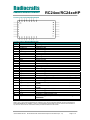
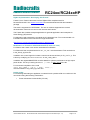
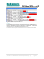
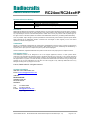
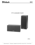
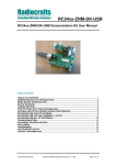
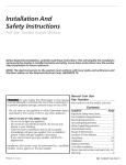
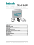
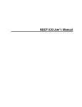
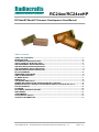
Radiocrafts
Embedded Wireless Solutions
RC24xx/RC24xxHP
RC24xx/RC24xxHP Firmware Development User Manual
Table of contents
TABLE OF CONTENTS............................................................................................................ 1
INTRODUCTION ....................................................................................................................... 2
DOCUMENTATION STRUCTURE ........................................................................................... 2
QUICK PRODUCT INTRODUCTION........................................................................................ 2
PIN ASSIGNMENT RC2400/RC2400HP .................................................................................. 3
PIN DESCRIPTION RC2400/RC2400HP ................................................................................. 3
PIN ASSIGNMENT RC2410/RC2410HP .................................................................................. 4
PIN DESCRIPTION RC2410/RC2410HP ................................................................................. 4
BLOCK DIAGRAM.................................................................................................................... 6
EMBEDDED RESOURCES ...................................................................................................... 6
CIRCUIT DESCRIPTION .......................................................................................................... 6
I/O RESOURCES ...................................................................................................................... 7
IEEE 802.15.4............................................................................................................................ 8
THE ZIGBEE PROTOCOL........................................................................................................ 8
ZIGBEE IMPLEMENTATION: DEVELOPING WITH Z-STACK............................................... 9
MODIFICATION OF Z-STACK FOR RC24XX/RC24XXHP (Z-STACK REV 2.3.0)................. 9
PACKET SNIFFER.................................................................................................................... 9
6LOWPAN............................................................................................................................... 10
DOCUMENT REVISION HISTORY......................................................................................... 11
DISCLAIMER .......................................................................................................................... 11
TRADEMARKS ....................................................................................................................... 11
LIFE SUPPORT POLICY ........................................................................................................ 11
CONTACT INFORMATION..................................................................................................... 11
©2010 Radiocrafts AS
RC24xx/RC24xxHP Firmware Development User Manual (rev. 1.2)
Page 1 of 11
Radiocrafts
Embedded Wireless Solutions
RC24xx/RC24xxHP
Introduction
This document with references includes all required information to develop a customerspecific firmware solution on the RC24xx/RC24xxHP hardware platforms.
Documentation structure
This document is one part of the documentation for the module. The data sheet describes the
electrical parameters, RF performance, footprint and PCB layout and regulatory information.
Depending on the selected FW solution, additional User Manuals should be used. The
available documents for the RC24xx product series are:
•
•
•
•
RC2400/RC2400HP Data sheet
RC241x/RC241xHP Data sheet
RC24xx/RC24xxHP Firmware Development User Manual (this document)
RC24xx/RC24xxHP-ZNM User Manual - Details on how to use the ZNM (ZigBee(R)
Network Management) module with preloaded ZigBee Pro stack and API through
serial interface.
RC24xx/RC24xxHP User
Manual (This document)
RC24xx/RC24xxHP-ZNM
User Manual
Future User Manuals
RC2400/RC2400HP Datasheet
RC2410/RC2410HP Datasheet
Figure 1 Document structure
Quick Product Introduction
The RC24xx series of modules are complies with the IEEE 802.15.4 standard used by ZigBee
PRO, 6LoWPAN and a number of other standards operating on IEEE 802.15.4. The module
together with the TI Z-stack or any other ZigBee network implementation is a powerful
combination for any ZigBee profile and application. The module contains qualified RF
hardware and enough processor power to run the complete ZigBee mesh network protocol for
a full function device including the application.
Using a pre-qualified module is the fastest way to make a ZigBee product with shortest time
to market. With all the RF HW and MCU resources you need in a 100% RF tested and prequalified module the qualification and approval process is shortest possible. No RF design or
expertise is required to add powerful wireless networking to any product. In the simplest case
like a home light remote control you only need an external battery and a pushbutton.
©2010 Radiocrafts AS
RC24xx/RC24xxHP Firmware Development User Manual (rev. 1.2)
Page 2 of 11
Radiocrafts
Embedded Wireless Solutions
RC24xx/RC24xxHP
Pin Assignment RC2400/RC2400HP
Pin Description RC2400/RC2400HP
Pin no Pin name
Description
1
GND
System ground
2
CTS/P0_4
CC2530 P0 [4]
3
RTS/P0_5/
CC2530 P0 [5]
4
P0_1
CC2530 P0 [1]
5
TXD/P0_3
CC2530 P0 [3]
6
RXD/P0_2
CC2530 P0 [2]
7
GND
System ground
8
GND
System ground
9
RF
RF I/O connection to antenna
10
GND
System ground
11
NC
Not Connected
12
RESET
CC2530 RESET_N. Active Low
13
VCC
Supply voltage input. Internally regulated.
14
GND
System ground
15
P0_7
CC2530 P0 [7]/HGM for RC2400HP
16
P1_2
CC2530 P1 [2]
17
P0_6
CC2530 P0 [6]
18
P2_0
CC2530 P2 [0]
19
P2_1/DD
Debug Data P2 [1]. Debug interface is used for programming.
20
P2_2/DC
Debug Clock P2 [2]. Debug interface is used for programming.
21
P0_0
CC2530 P0 [0]
22
P1_3
CC2530 P1 [3] /EN for RC2400HP
23
P2_4/32kHz_Q1
Internal 32 kHz crystal oscillator. Do not connect. (P2.4 if no
crystal)
24
P2_3/32kHz_Q2
Internal 32 kHz crystal oscillator. Do not connect. (P2.3 if no
crystal)
25
P1_7
CC2530 P1 [7]/GIO/UART RX
26
P1_6
CC2530 P1 [6]/GIO/UART TX
27
P1_5
CC2530 P1 [5]/GIO/UART RTS
28
P1_4
CC2530 P1 [4]/GIO/UART CTS
29
P1_1
CC2530 P1 [1] with optional ADC input. LED driver/PA_EN for
RC2400HP
30
P1_0
CC2530 P1 [0] with optional ADC input. LED Driver
Note 3: Pins 17 and 18 are suggested as I2C interface. They can be configured otherwise, but are connected to an
internal EEPROM with I2C address = 000. It is recommended to leave these pins as I2C. Sensors and actuators or
any other I2C device can be connected to these pins and accessed from the module.
©2010 Radiocrafts AS
RC24xx/RC24xxHP Firmware Development User Manual (rev. 1.2)
Page 3 of 11
Radiocrafts
Embedded Wireless Solutions
RC24xx/RC24xxHP
Pin Assignment RC241x/RC241xHP
53
34
1
Radiocrafts
33
31
10
11
30
Pin Description RC241x/RC241xHP
Pin no
1
2
3
4
5
6
7
8
9
10
11
12
13
14
15
16
Pin name
GND
NC
NC
GND
P0_4
P0_5
P0_1
P0_3
P0_2
GND
GND
P0_7
P1_2
P0_6
P0_0
P1_3
17
18
19
20
21
22
23
24
25
26
27
28
29
30
RESET_N
NC
NC
NC
NC
NC
NC
NC
NC
NC
NC
NC
NC
GND
©2010 Radiocrafts AS
Description and internal MCU connection
System ground
Reserved for optional USB_M on CC2531
Reserved for optional USB_P on CC2531
System ground
CC2530, P0_4
CC2530, P0_5
CC2530, P0_1
CC2530, P0_3
CC2530, P0_2
System ground
System ground
CC2530, P0_7, HGM for PA CTRL IN HP VERSION
CC2530, P1_2, Chip select for SPI FLASH
CC2530, P0_6, Connencted to EEPROM if mounted
CC2530, P0_0
CC2530, P1_3 ENABLE(LNA_ENABLE) FOR PA CTRL IN HP
VERSION
RESET for CC2530
Not connected
Not connected
Not connected
Not connected
Not connected
Not connected
Not connected
Not connected
Not connected
Not connected
Not connected
Not connected
System ground
RC24xx/RC24xxHP Firmware Development User Manual (rev. 1.2)
Page 4 of 11
Radiocrafts
Embedded Wireless Solutions
31
32
GND
RF_TEST
33
34
35
36
37
38
39
40
41
42
43
44
45
46
47
48
49
50
51
52
53
GND
GND
VCC
NC
NC
NC
NC
NC
SPI_FLASH_RESET
P2_4
P2_3
P2_2
P2_1
P2_0
P1_7
P1_6
P1_5
P1_4
P1_1
P1_0
GND
©2010 Radiocrafts AS
RC24xx/RC24xxHP
System ground
RF I/O connection for Automatic test purposes.
- For components intended for use with UFL connector, do not
connect this pad.
System ground
System ground
VCC
Not connected
Not connected
Not connected
Not connected
Not connected
RESET for SPI flash, NC for without SPI flash
CC2530, P2_4, Connected to 32kHz crystal
CC2530, P2_3, Connected to 32kHz crystal
CC2530, P2_2/DC
CC2530, P2_1/DD
CC2530, P2_0, Connencted to EEPROM if mounted
CC2530, P1_7, Connected to SPI flash
CC2530, P1_6, Connected to SPI flash
CC2530, P1_5, Connected to SPI flash
CC2530, P1_4
CC2530, P1_1, PA ENABLE FOR PA CTRL IN HP VERSION
CC2530, P1_0
System ground
RC24xx/RC24xxHP Firmware Development User Manual (rev. 1.2)
Page 5 of 11
Radiocrafts
Embedded Wireless Solutions
RC24xx/RC24xxHP
Block Diagram
RC24xxHP
PA
CC2591
Low noise
amplifier
CC2591
UART
Communication
controller
CC2530
RF
Tranceiver
CC2530
Embedded resources
MCU:
Enhanced single-cycle 8051 with 256 kB Flash
PHY/MAC:
Texas Instruments (TI) CC2530, and CC2591 for RC24xxHP
Connection between CC2530 and CC2591 are as follows.
CC2530
P1_1
P1_3
P0_7
Firmware:
CC2591
PA_EN
EN
HGM
Not included, but ZigBee and IEEE 802.15.4 firmware can be downloaded for
free from www.ti.com.
For 6LoWPAN stack please contact [email protected].
For module with preloaded ZigBee stack see RC24xx-ZNM, ZigBee Network Module.
Circuit Description
The module contains an IEEE 802.15.4 compliant SoC RF transceiver, internal EEPROM
(optional), high speed oscillator and an RTC 32 kHz oscillator.
The module includes two USART that are configurable as either SPI or UART. Totally 19 I/O
pins are available to the user. 8 pins can be used for the internal 8-12 bit A/D converter. All of
the pins have interrupt features.
The MCU provides several low power modes with can be utilized to reduce the current
consumption in battery operated applications. An optional internal 32 kHz crystal oscillator
can be used for real-time clock and timer applications.
The module has an internal POR circuit and a brown out detector, but it is still highly
recommended to add an external power supervisory circuit to ensure a proper reset when a
power fault has occurred.
For further details on the SoC transceiver (TI CC2530 and CC2591), please consult the
respective data sheet.
©2010 Radiocrafts AS
RC24xx/RC24xxHP Firmware Development User Manual (rev. 1.2)
Page 6 of 11
Radiocrafts
Embedded Wireless Solutions
RC24xx/RC24xxHP
PA_EN
0
1
1
2
1
CT
RT
Q2
EN
0
RT
Q1
1
1
MI
RX
0
TX
MO
C
TX
SS
RX
MI
MO
C
4
0
CT
1
RT
SS
C
TX
MO
MI
RX
3
HGM
0
CT
SS
4
0
DC
DD
X
X
X
X
X
©2010 Radiocrafts AS
RC24xx/RC24xxHP Firmware Development User Manual (rev. 1.2)
CC2591 CTRL in RC2400HP
/RC241xHP
DEBUG
32 kHz XOSC
Alt2
Timer4
Alt2
Timer3
Alt2
2
Timer1
Alt2
USART1 UART
Alt2
TX
3
RX
MI
MO
USART1 SPI
Alt2
USART0 UART
Alt2
USART0 SPI
SS
CT
C
RT
X
X
X
ADC
P0_4 P0_5 P0_1 P0_3 P0_2 P0_7 P1_2 P0_6 P2_0 P2_1 P2_2 P0_0 P1_3 P2_4 P2_3 P1_7 P1_6 P1_5 P1_4 P1_1 P1_0
Port/
Function
30
29
28
27
26
25
24
23
22
21
20
19
18
17
16
15
6
5
4
3
2
PIN RC2400/RC2400HP
PIN RC241x/RC241xHP
5
6
7
8
9
12
13
14
46
45
44
15
16
42
43
47
48
49
50
51
52
I/O resources
The module has 19 digital I/O pins, but in case of -HP or with the inclusion of RTC the pin
number available for application is slightly lower. They are shown in the table below together
with the additional I/O feature associated with them. When using -HP modules the pins P1_1,
P1_3 and P0_7 must be left unconnected.
Page 7 of 11
Radiocrafts
Embedded Wireless Solutions
RC24xx/RC24xxHP
IEEE 802.15.4
The IEEE 802.15.4 standard provides a worldwide standard for Personal Area Networks and
short distance wireless networks for low data rate solutions with long battery life and low
complexity. The standard defines a Physical layer (PHY) and a Medium Access Control layer
(MAC). There are two active versions of the standard: IEEE 802.15.4-2003 and IEEE
802.15.4-2006 where the 2003 version is a basis for the ZigBee protocol. The typical
applications are meter reading, home and building automation, industrial control and
monitoring systems, wireless sensor networks, remote controls and consumer electronics.
The module complies with the IEEE 802.15.4 standard operating in the 2.45 GHz band. It
uses direct sequence spread spectrum (DSSS) with 2 Mc/s chip rate giving a raw data rate of
250 kbit/s. 16 channels are available in the 2.45 GHz band named channel 11 – 26 (channels
0-10 are reserved for use in the 868 and 915 MHz bands).
For more information on the standard, please consult www.ieee802.org/15/pub/TG4.html
The ZigBee Protocol
The ZigBee Alliance is an association of companies working together to enable reliable, costeffective, low-power, wirelessly networked, monitoring and control products based on an open
global standard. The ZigBee Alliance is a rapidly growing, non-profit industry consortium of
leading semiconductor manufacturers, technology providers, OEMs and end-users worldwide.
Membership is open to all. The ZigBee Alliance, in collaboration with the IEEE, is defining the
network, security, and application layers above the IEEE 802.15.4 PHY and MAC layers. This
cooperation has resulted in an easy-to-use, industry standard wireless network platform
optimised for wireless monitoring and control applications.
The ZigBee standard defines a Network Layer and an Application Layer on top of IEEE
802.15.4. The network layer includes routing, security etc. while the application layer defines
binding and other support for application.
The applications are specified in profiles to ensure multi-vendor interoperability. Current
public profile includes:
- Smart Energy - SE (Profile for Smart Meter reading)
- Building Automation - CBA
- Home Automation - HA
- Health Care - HC
- Telecom Services - TA
- Remote Control - RF4CE
Manufacturer specific profiles can also be made.
The current version of the ZigBee standard is 2007. The standard defines two different stack
feature sets:
- ZigBee Feature set
- ZigBee PRO feature set
In order to sell a product containing ZigBee technology, the seller must be a member (adaptor
or higher) of the ZigBee alliance.
For more information about the ZigBee Alliance and the ZigBee standard, please consult
www.zigbee.org.
©2010 Radiocrafts AS
RC24xx/RC24xxHP Firmware Development User Manual (rev. 1.2)
Page 8 of 11
Radiocrafts
Embedded Wireless Solutions
RC24xx/RC24xxHP
ZigBee implementation: Developing with Z-stack
Z-stack™ from Texas Instruments is a free ZigBee PRO compliant stack for
RC24xx/RC24xxHP. See www.ti.com/z-stack for stack download and full documentation
package.
The stack is supported for IAR EW8051. For info on revisions supported see z-stack
documentation. See www.iar.com for trial versions and licences.
The Z-stack also includes example application for general applications and examples for
Smart Energy (SE) devices.
For debugging and programming a module the CC-debugger from TI is recommended. It is
included in the demo kit and can also be bought online here:
http://focus.ti.com/docs/toolsw/folders/print/cc-debugger.html
Modification of Z-stack for RC24xx/RC24xxHP (Z-stack rev 2.3.0)
For RC24xx the z-stack 2.3.0 can be used without modification.
For RC24xxHP the compile directive for HAL_PA_LNA must be activated. This can be done
in hal_board_cfg.h line 64.
In addition one control signal for CC2591 control must be moved from pin P1_4 to P1_3. This
is done by modifying OBSSEL4 to OBSSEL3 in mac_radio_defs.c
In addition the register MDMTEST0 must be altered for optimum preformance at high output
power levels. This is by inserting MDMTEST0 |= 0x80; in mac_mcu.h line 186
For successful compilation of the code
uint8 OSC_32KHZ = ((P1_2) ? 0x00 : 0x80); \
must be inserted in hal_board_cfg.h line 320
Packet sniffer
For evaluating and testing an application on network level a packet sniffer is a useful tool. We
recommend using the following combination:
•
Texas Instruments Packet Sniffer (PC tool)
©2010 Radiocrafts AS
RC24xx/RC24xxHP Firmware Development User Manual (rev. 1.2)
Page 9 of 11
Radiocrafts
Embedded Wireless Solutions
RC24xx/RC24xxHP
Figure 2 Screenshot from packet sniffer
6LoWPAN
6LoWPAN is an acronym for IPv6 over LoW power Wireless Personal Area Network and is a
standard for transmitting IPv6 packets over IEEE 802.15.4 compliant radios. The standard is
open and maintained by the 6LoWPAN working group with in IETF.
RC24xx/RC24xxHP is compliant with 6LoWPAN and a stack is available from third parties.
©2010 Radiocrafts AS
RC24xx/RC24xxHP Firmware Development User Manual (rev. 1.2)
Page 10 of 11
Radiocrafts
Embedded Wireless Solutions
Document Revision History
Document Revision
1.0
1.1
1.2
RC24xx/RC24xxHP
Changes
First release
Updated with reference RC2410/RC2410HP
Corrected I/O resource table, P0_2/P0_3 swapped. Included RC241xHP in
the table
Disclaimer
Radiocrafts AS believes the information contained herein is correct and accurate at the time of this printing. However,
Radiocrafts AS reserves the right to make changes to this product without notice. Radiocrafts AS does not assume
any responsibility for the use of the described product; neither does it convey any license under its patent rights, or
the rights of others. The latest updates are available at the Radiocrafts website or by contacting Radiocrafts directly.
As far as possible, major changes of product specifications and functionality, will be stated in product specific Errata
Notes published at the Radiocrafts website. Customers are encouraged to check regularly for the most recent
updates on products and support tools.
Trademarks
RC232™ is a trademark of Radiocrafts AS. The RC232™ Embedded RF Protocol is used in a range of products from
Radiocrafts. The protocol handles host communication, data buffering, error check, addressing and broadcasting. It
supports point-to-point, point-to-multipoint and peer-to-peer network topologies.
All other trademarks, registered trademarks and product names are the sole property of their respective owners.
Life Support Policy
This Radiocrafts product is not designed for use in life support appliances, devices, or other systems where
malfunction can reasonably be expected to result in significant personal injury to the user, or as a critical component
in any life support device or system whose failure to perform can be reasonably expected to cause the failure of the
life support device or system, or to affect its safety or effectiveness. Radiocrafts AS customers using or selling these
products for use in such applications do so at their own risk and agree to fully indemnify Radiocrafts AS for any
damages resulting from any improper use or sale.
© 2010, Radiocrafts AS. All rights reserved.
Contact Information
Web site: www.radiocrafts.com
Email: [email protected]
Address:
Radiocrafts AS
Sandakerveien 64
NO-0484 OSLO
NORWAY
Tel:
+47 4000 5195
Fax:
+47 22 71 29 15
E-mail: [email protected]
[email protected]
©2010 Radiocrafts AS
RC24xx/RC24xxHP Firmware Development User Manual (rev. 1.2)
Page 11 of 11