1
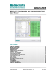
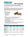
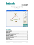
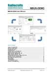
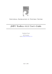
Radiocrafts Embedded Wireless Solutions MBUS-CCT MBUS-CCT (Configuration and Communication Tool) User Manual Table of Contents TABLE OF CONTENTS ............................................................................................................ 1 INSTALLATION GUIDE ............................................................................................................ 2 SCREEN SETTINGS ................................................................................................................. 2 INTRODUCTION ....................................................................................................................... 2 CONNECTING TO THE MODULE............................................................................................ 3 TERMINAL MODE .................................................................................................................... 4 CYCLICAL TEXT SENDING ..................................................................................................... 5 CONFIGURATION MODE ........................................................................................................ 6 CHANGING MODULE PARAMETERS .................................................................................... 7 CONFIGURATION FILES ......................................................................................................... 8 TEST MODES ........................................................................................................................... 9 RSSI READING ......................................................................................................................... 9 MBUS-CCT OTA STEP-BY-STEP GUIDE ............................................................................. 10 DOCUMENT REVISION HISTORY......................................................................................... 13 DISCLAIMER .......................................................................................................................... 13 TRADEMARKS ....................................................................................................................... 13 LIFE SUPPORT POLICY ........................................................................................................ 13 CONTACT INFORMATION ..................................................................................................... 13 2015 Radiocrafts AS MBUS-CCT User Manual (rev. 1.1) Page 1 of 13 Radiocrafts Embedded Wireless Solutions MBUS-CCT Installation Guide MBUS-CCT (Configuration and Communication Tool) is a part of Radiocrafts RCTools-MBUS PC suite tailored for use with Radiocrafts Wireless M-Bus RF Modules. For full installation procedure please read the RCTools Installation Guide available at www.radiocrafts.com. The MBUS-CCT requires access to the modules UART via an available COM-port. Typically UART-access is obtained via an UART-to-RS232 or UART-to-USB converter. The Demo Boards (DB) from Radiocrafts contains an on-board level shifter for direct plug-in to a PC and further access to the related COM-port. Screen Settings It is recommended to run the application with screen size at least 1024x768 and font resolution 96dpi. Introduction The MBUS-CCT helps you to work with the Radiocrafts RC1180-MBUS module series. The program enables you to easily configure the module, and can additionally work as a terminal window where data can be sent or received to / from any serial port. Figure 1. Main window Connect the DB, or your own hardware with the Radiocrafts module, to the COM-port. Start the program and the programs main window should look similar to what is shown in Figure 1. 2015 Radiocrafts AS MBUS-CCT User Manual (rev. 1.1) Page 2 of 13 Radiocrafts Embedded Wireless Solutions MBUS-CCT Connecting to the Module Before connecting, select the proper settings for your serial port: • name of an available communication port (COMx) • baud rate used to communicate with the module Figure 2. Port settings To connect to the module you need to press the connect button. Figure 3. Connect button If you do not know what baud rate the module is configured for, there is a possibility to detect the baud rate automatically by pressing the autobaud detection button: Figure 4. Autobaud button To perform automatic baud rate detection the module will have to enter configuration mode. To do so, you will be asked either to press the configuration button on the board or to use a strap connecting RTS line (at UART voltage level) with CONFIG pin on the module. After pressing auto detect button you will be asked to indicate if you are using the strap or if you use the configuration (CONFIG) button. In the second case, you need to press it before continuing auto detection. When the baud rate is detected successfully the program will automatically connect to the board and go into terminal mode. If the correct baud rate is not detected properly at the first attempt, retry the autobaud process. 2015 Radiocrafts AS MBUS-CCT User Manual (rev. 1.1) Page 3 of 13 Radiocrafts Embedded Wireless Solutions MBUS-CCT Terminal Mode After pressing the connect button, the program opens a port and enters terminal mode. You now have the possibility to send and receive data to / from the selected serial port. Figure 5. Terminal part of window Everything written in the bottom line of the terminal part (right side) of the window will be sent to the serial port when <enter> or the arrow-button to the right is pressed. All data sent to the serial port is highlighted in blue, and all the data that have been received is highlighted in green in the upper part of the window. Important: When blue data appears, it doesn’t guarantee that this data has been sent over RF, it has been sent into the serial port only, as this depends on the state of the RF module. To send ASCII characters, type them in and hit the enter key or click on the send once button. To send bytes, you need to use apostrophes. For example, to send 5 bytes with values: 0x33, 0x25, 6, 78, 7 you need to write: Figure 6. Terminal line with numbers 2015 Radiocrafts AS MBUS-CCT User Manual (rev. 1.1) Page 4 of 13 Radiocrafts Embedded Wireless Solutions MBUS-CCT Note that the MBUS modules require that the first byte to the UART is a length byte. Both decimal and hexadecimal values can be used. You can mix ASCII, decimal and hexadecimal values in one sting for instance if you want to send a Q command when you are in configuration mode: Figure 7. Terminal line with MBUS Commands To clear the terminal window, click the small white paper-icon at top-right. To save the content of the terminal window perform; File->Save Terminal Window, or Ctrl-T. Drag-and-drop; By drag-and-drop a proper formatted file into the programs terminal window while being in terminal mode, the contents of the file will be sent to the serial port. You will be asked if it should be parsed. By pressing “no”, it will be sent as a normal text file as it is written in the file. By pressing “yes” the program will treat every line of the file as a single line entry into the terminal window. Cyclical text sending A selectable text-string can be sent at regular intervals (every second) from terminal mode. Figure 8. Send text cyclically The sent text is taken from the terminal line at the moment of pressing the button. 2015 Radiocrafts AS MBUS-CCT User Manual (rev. 1.1) Page 5 of 13 Radiocrafts Embedded Wireless Solutions MBUS-CCT Configuration Mode To enter configuration mode, press the configure button; Figure 9. Configuration mode entry button The program will wait 15 seconds for a prompt sign, which is sent from the module when configuration mode is entered. To get the prompt from the module you need to push the CONFIG button on the Demo board or write ‘0x00’ from the terminal window. Figure 10. Waiting for a prompt If you use an RTS line to control the CONFIG line into a module, the program asserts RTS low automatically. If you use RTS line for some other purpose, you can disable this feature with the small button next to RTS lines state indicator. If you have connected your own boards to MBUS-CCT and you do not have access to the CONFIG pin, you can type ‘0x00’ in the terminal entry window and send it to the module. Figure 11. RTS lines state indicator Figure 12. Configuration mode In configuration mode there is easy access to all of the modules configuration parameters. First thing to do after entering communication mode is to read the configuration from the module by pressing the left-arrow in the “Non-Volatile Configuration Memory” section. 2015 Radiocrafts AS MBUS-CCT User Manual (rev. 1.1) Page 6 of 13 Radiocrafts Embedded Wireless Solutions MBUS-CCT Figure 13. Loading and sending configuration When the configuration is loaded, you can see all the settings of the module. You can also see the module name, hardware and firmware revisions. Figure 14. Modules name and hardware and firmware revisions As can be seen from the window, parameters are divided into sections. In the volatile memory section there are a total of three parameters that are not stored in a permanent memory, thus they are erased after resetting the module (or power lost). There is no way to check the values of the parameters in volatile memory, so there is only a button for sending entered parameters into the module. In the non-volatile configuration memory section the parameters stored in the permanent memory are found. The parameters having a gray background should not be changed as this might cause reduced performance. The Wireless M-Bus module includes a command set to change some specific parameters in configuration mode. These commands can be send to the module by typing the hex value bytes in the terminal window. Changing Module Parameters To change a parameter, type a value in a “Dec” or “Hex” column in the data grid for decimal or hexadecimal values respectively. To write the settings into the CONFIG memory, press the “send to module” button (right-arrow). Only the differences between previously loaded and new typed configurations are sent, as can be seen from the hexadecimal communication towards the module in the terminal window. When you enter a new configuration parameter value, the program will also check the new value against constraints for the parameter to prevent invalid configuration. You can see the constraint in a status bar, when moving the cursor over any row in the table. Figure 15. Hint in a status bar There is a pop-up hint/help window for every parameter, just move and hold the cursor over it. There are hints and help for most parameters and parts of the interface. 2015 Radiocrafts AS MBUS-CCT User Manual (rev. 1.1) Page 7 of 13 Radiocrafts Embedded Wireless Solutions MBUS-CCT Figure 16. Pop-up hint When leaving the configuration mode, do so either by pressing the disconnect button or by pressing the terminal mode button. Figure 17. Terminal mode button Important notes: 1. It is strongly recommended to leave the configuration mode as described above to avoid situations where you start to use the module in your application while the module is still in configuration mode. 2. After entering some values into non-volatile memory you have to reset the module to make them active. Parameters entered into the volatile memory section works immediately after sending. 3. After changing the baud rate you have to reset and reconnect at the proper baud rate. Configuration Files Configurations can be stored in .rcc files. After reading the configuration from a module, it can be stored by selecting File->Save configuration (Ctrl + S). You can also load a configuration from file. These files are a reflection of all 128 bytes of the configuration memory. You can load the default factory configuration by selecting File->Load defaults->This model . To do so, you need to be in configuration mode. When you load defaults, all 128 configuration memory bytes are reset to defaults. The wanted .rcc-file can also be dragged and dropped into the Non-Volatile Configuration Memory window. Always ensure that you are loading a proper configuration file. After dropping the file a prompt will ask if the contents shall be sent to the module or the settings just entered as data in the window. It may happen that the configuration memory is changed (by accident) in a way so the CCT program cannot resolve what model it is connected to. If so, you should manually select the model that you are using in File->Load defaults. Be aware that loading defaults or configuration (.rcc) for a different model than you are actually using can cause module to malfunction. 2015 Radiocrafts AS MBUS-CCT User Manual (rev. 1.1) Page 8 of 13 Radiocrafts Embedded Wireless Solutions MBUS-CCT Test Modes For most modules there are available test modes, which can be entered in a dedicated part of the program window. Figure 18. Test modes Next to this box there are two buttons to use with test modes: Figure 19. Buttons for test modes The left button enables the selected test mode. You can see the sent hex-sequence in the terminal window. Every time configuration data is sent to the module the CCT-program automatically exits test mode. If you want to change current channel or power and still remain in a test mode, use the right button with a lock. With this enabled, every time you send data to the volatile memory the selected test mode will be turned on again. RSSI Reading RSSI signal strength is displayed both as the decimal value of the byte received from the module and the calculated dBm-value. Figure 20. RSSI reading When the module is placed in a test mode the RSSI reading might not be correct. Leave test mode to display the correct RSSI value. 2015 Radiocrafts AS MBUS-CCT User Manual (rev. 1.1) Page 9 of 13 Radiocrafts Embedded Wireless Solutions MBUS-CCT MBUS-CCT OTA step-by-step guide This informs how to reconfigure the RC170xHP-MPC1 module Over The Air (OTA) using a RC170xHP-MBUS4 DB connected to a PC running the MBUS-CCT 1.30 PC application. USB UART connection RF OTA Connection RC170xHP-MBUS4 DB RC170xHP-MPC1 Step-by-step guide: 1. Ensure MBUS-CCT is rev 1.30 B7 or greater 2. Ensure RC170xHP-MPC1 is rev 0B50 Release2 or greater 3. Change RC170xHP-MBUS4 default parameter to MBUS_MODE=17 (0x11) and UART_BUAD_RATE=11 (0x0B). 4. Reset RC170xHP-MBUS4 and reconnect to board at UART Baud Rate 230400. 5. Enter configuration mode in MBUS-CCT by clicking the configuration mode button and wait 2 seconds. 2015 Radiocrafts AS MBUS-CCT User Manual (rev. 1.1) Page 10 of 13 Radiocrafts Embedded Wireless Solutions MBUS-CCT 6. Enable OTA configuration in MBUS-CCT in the OTA checkbox selction 7. Click Left arrow to OTA read from MPC1. 8. A pop-up window will show up and waiting for you to push CONFIG low on remote MPC1 module. 9. Push CONFIG low on remote MPC1 module. The Non-Volatile Configuration memory table in the MBUS-CCT will be filled with remote MPC1 configuration memory and The pop-up windows will close. 10. You can now change any parameter in the table and MBUD-CCT will prepare packet to transmit to the remote MPC1 module 2015 Radiocrafts AS MBUS-CCT User Manual (rev. 1.1) Page 11 of 13 Radiocrafts Embedded Wireless Solutions MBUS-CCT 11. Click right arrow to send new configuration data to remote MPC1 12. A pop-up window will show up and waiting for you to push CONFIG low on remote MPC1 module before MBUS-CCT send the new configuration data OTA. 13. 14. Push CONFIG low on remote MPC1 module. The pop-up windows will close when the MBUS-CCT has send new data to remote MPC1. This may take several seconds. 15. You can verify the new configuration by repeating step 7-9. 2015 Radiocrafts AS MBUS-CCT User Manual (rev. 1.1) Page 12 of 13 Radiocrafts MBUS-CCT Embedded Wireless Solutions Document Revision History Document Revision 1.0 1.1 Changes New Revision, based on RC232-CCT User Manual OTA information for MPC1 included Disclaimer Radiocrafts AS believes the information contained herein is correct and accurate at the time of this printing. However, Radiocrafts AS reserves the right to make changes to this product without notice. Radiocrafts AS does not assume any responsibility for the use of the described product; neither does it convey any license under its patent rights, or the rights of others. The latest updates are available at the Radiocrafts website or by contacting Radiocrafts directly. As far as possible, major changes of product specifications and functionality, will be stated in product specific Errata Notes published at the Radiocrafts website. Customers are encouraged to check regularly for the most recent updates on products and support tools. Trademarks MBUS™ is a trademark of Radiocrafts AS. The MBUS™ Embedded RF Protocol is used in a range of products from Radiocrafts. The protocol handles host communication, data buffering, error check, addressing and broadcasting. It supports point-to-point, point-to-multipoint and peer-to-peer network topologies. All other trademarks, registered trademarks and product names are the sole property of their respective owners. Life Support Policy This Radiocrafts product is not designed for use in life support appliances, devices, or other systems where malfunction can reasonably be expected to result in significant personal injury to the user, or as a critical component in any life support device or system whose failure to perform can be reasonably expected to cause the failure of the life support device or system, or to affect its safety or effectiveness. Radiocrafts AS customers using or selling these products for use in such applications do so at their own risk and agree to fully indemnify Radiocrafts AS for any damages resulting from any improper use or sale. © 2008, Radiocrafts AS. All rights reserved. Contact Information Web site: www.radiocrafts.com Address: Radiocrafts AS Sandakerveien 64 NO-0484 OSLO NORWAY Tel: +47 4000 5195 Fax: +47 22 71 29 15 E-mails: [email protected] [email protected] [email protected] 2015 Radiocrafts AS MBUS-CCT User Manual (rev. 1.1) Page 13 of 13