1
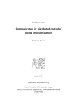
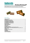
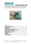
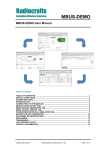
Radiocrafts
Embedded Wireless Solutions
RC2400-ZNM/RC2400HP-ZNM
ZigBee® PRO Network Module - User Manual
Table of contents
TABLE OF CONTENTS............................................................................................................ 1
INTRODUCTION ....................................................................................................................... 2
QUICK PRODUCT INTRODUCTION........................................................................................ 2
DOCUMENTATION STRUCTURE ........................................................................................... 2
PIN ASSIGNMENT.................................................................................................................... 3
PIN DESCRIPTION ................................................................................................................... 3
PIN CONFIGURATION ............................................................................................................. 4
SERIAL COMMUNICATION ..................................................................................................... 4
SPI INTERFACE ....................................................................................................................... 4
UART INTERFACE ................................................................................................................... 4
GENERAL FRAME FORMAT................................................................................................... 5
API COMMAND SET ................................................................................................................ 6
STATES OF OPERATION ........................................................................................................ 7
CONFIGURATION .................................................................................................................... 7
OPERATION ............................................................................................................................. 9
API COMMAND SET .............................................................................................................. 10
ZNM-SE ................................................................................................................................... 14
DOCUMENT REVISION HISTORY......................................................................................... 16
DISCLAIMER .......................................................................................................................... 16
TRADEMARKS ....................................................................................................................... 16
LIFE SUPPORT POLICY ........................................................................................................ 16
CONTACT INFORMATION..................................................................................................... 16
©2010 Radiocrafts AS
RC2400ZNM/RC2400HP-ZNM User Manual (rev. 1.1)
Page 1 of 16
Radiocrafts
Embedded Wireless Solutions
RC2400-ZNM/RC2400HP-ZNM
Introduction
This document includes or refers to all the needed information to develop solution with the
RC2400-ZNM and RC2400HP-ZNM modules.
Quick Product Introduction
The ZNM series of modules are specially designed to meet the IEEE 802.15.4 standard and
ZigBee PRO specification. It is preloaded with a ZigBee PRO compliant stack and offers an
easy to use API via UART or SPI to an external processor. The external application processor
can be of any type or brand, and the development can be done with the tool and platform
most convenient to the developer.
Application processor
RC2400-ZNM/RC2400HP-ZNM
Application
SPI/UART interface
UART/SPI
SPI/UART interface
Application Support Sublayer
ZigBee PRO stack
802.15.4 MAC
AES encryption
IEEE 802.15.4 Radio
Figure 1 ZigBee Network Module concept
Using a pre-qualified module is the fastest way to make a ZigBee product with shortest time
to market. With all the RF HW and MCU resources you need in a 100% RF tested and prequalified module the qualification and approval process is shortest possible. No RF design or
expertise is required to add powerful wireless networking to any product.
Documentation structure
This document is one part of the documentation for the module. The data sheet describes the
electrical parameters, RF performance, footprint and PCB layout and regulatory information.
Depending on the selected FW solution, additional User Manuals should be used. The
available documents for the RC2400 product series are:
•
•
•
RC2400/RC2400HP Data sheet
RC2400/RC2400HP Firmware Development User Manual - Details on how to develop
customer specific firmware for RC2400 HW platform
RC2400/RC2400HP-ZNM User Manual (This document)
RC2400/RC2400HP
User Manual
RC2400/RC2400HP-ZNM User
Manual (This document)
Future User Manuals
RC2400/RC2400HP Datasheet
Figure 2 Document structure
©2010 Radiocrafts AS
RC2400ZNM/RC2400HP-ZNM User Manual (rev. 1.1)
Page 2 of 16
Radiocrafts
Embedded Wireless Solutions
RC2400-ZNM/RC2400HP-ZNM
Pin Assignment
Pin Description
I
Pin no Pin name
1
GND
2
CTS
3
RTS
4
5
TXD
6
RXD
7
GND
8
GND
9
RF
10
GND
11
NC
12
Reset
13
VCC
14
GND
15
16
ZNM-Cfg0
17
18
19
20
21
22
23
24
25
26
27
28
29
30
ZNM-Cfg1
DD
DC
GPIO
32kHz_Q1
32kHz_Q2
©2010 Radiocrafts AS
Description
System ground
UART Clear to Send / SPI SRDY
UART Request to Send.
UART TX Data / SPI MRDY
UART RX Data
System ground
System ground
RF I/O connection to antenna
System ground
Not Connected
RESET_N. Active Low
Supply voltage input. Internally regulated.
System ground
LNA High Gain mode for RC2400HP
ZnmCfg0
0 = 32 kHz RTC crystal oscillator
1= 32 kHz RC oscillator
GPIO
ZnmCfg1
'0' = UART
'1' = SPI
Debug Data. Debug interface is used for programming.
Debug Clock. Debug interface is used for programming.
GPIO
EN for RC2400HP
Internal 32 kHz oscillator. Do not connect.
Internal 32 kHz oscillator. Do not connect.
SPI MI
SPI MO
SPI C
SPI SS
PA_EN for RC2400HP
GPIO with optional ADC input. LED Driver
RC2400ZNM/RC2400HP-ZNM User Manual (rev. 1.1)
Page 3 of 16
Radiocrafts
Embedded Wireless Solutions
RC2400-ZNM/RC2400HP-ZNM
Pin configuration
There are two pins of RC2400 that are used to hardwire the configuration of the module:
RC2400/
RC2400
HP pin
16
18
Signal name
Result
ZNM_Cfg0
'0' low = 32 kHz RTC crystal oscillator.
'1' high = 32 kHz RC oscillator
'0' low = UART
'1'high = SPI
ZNM_Cfg1
(Serial interface selection)
Serial Communication
Through a serial interface, either SPI or UART, the module/network can be configured and
data can be sent and received.
Any
MCU
Microcontroller
API via SPI/UART
SPI Interface
The SPI interface consists of these signals:
• SO
Slave output
• SI
Slave input
• CS
SPI clock
• SS
SPI Slave select
• MRDY Master ready
• SRDY Slave ready
The four upper signals are used for standard SPI operation with RC2400-ZNM as the slave.
The MRDY and SRDY are used for power control/flow control. MRDY -> low indicates that the
master has data to send and can be used to wake up the ZNM module from sleep. The
module will reply with SRDY --> low when it is ready to receive data.
The SPI interface has the following characteristics:
• RC2400-ZNM is an SPI slave
• Max clock speed = 4 MHz
• Clock polarity on RC2400-ZNM = 0
• Clock phase on RC2400-ZNM = 0
• Bit order MSB first
UART Interface
The UART interface is implemented as DTE and consists of these signals
•
•
•
•
RX
TX
CTS
RTS
-
©2010 Radiocrafts AS
RXD - data to module
TXD - data from module
Input to module
Output from module
RC2400ZNM/RC2400HP-ZNM User Manual (rev. 1.1)
Page 4 of 16
Radiocrafts
Embedded Wireless Solutions
RC2400-ZNM/RC2400HP-ZNM
The setting for the UART is as follows:
UART Configuration
Baud rate
115.2 kBaud*
Data bits
8
Parity
Even
Stop bit
1
Flow control
RTS/CTS (implemented as DTE)
*Contact [email protected] for other Baud rates
The frame format for the UART is as follows:
Start Of Frame(SOF)
0xFE
Commands
General frame format
Frame Check Sum- FCS (1 byte)
XOR of all bytes in General Data Format
General frame format
The general frame format for sending commands is as follow:
Length of data
1 byte
0xNN
©2010 Radiocrafts AS
Command ID
CMD0
CMD1
0xNN
NN
Data
0-253 bytes
0xNN NN ...
RC2400ZNM/RC2400HP-ZNM User Manual (rev. 1.1)
Page 5 of 16
Radiocrafts
Embedded Wireless Solutions
RC2400-ZNM/RC2400HP-ZNM
API command set
The set of API commands that can be sent via the UART/SPI interface can be divided into
four categories:
•
•
•
•
System commands
Simple API (SAPI) commands
AF commands
ZDO commands
System commands are for controlling the HW device and include commands for resetting the
module and utilizing resources within the module.
Simple API commands consist of only 10 commands which is the easiest way to build a
complete application that does network creation and sending/receiving of data.
AF commands are commands for registering application and sending data with complete
flexibility.
ZDO commands are commands for detailed control of ZigBee device operation regarding
ZigBee Device Object. This includes binding devices, finding and matching descriptors.
For a complete overview of the command interface see CC2530-ZNP Interface Specification.
©2010 Radiocrafts AS
RC2400ZNM/RC2400HP-ZNM User Manual (rev. 1.1)
Page 6 of 16
Radiocrafts
Embedded Wireless Solutions
RC2400-ZNM/RC2400HP-ZNM
States of operation
Start-up
Configuration
Operation
Figure 3 States of operation
The module has three distinct phases of operation.
• Start-up: At this transient phase configuration I/O pins are checked to enable UART
or SPI and whether 32 kHz crystal oscillator is present. Automatically transition to
Configuration state.
•
Configuration: Set-up of the ZNM module. (See details below). A start command
changes state to Operation
•
Operation: The device active the RF part and Create/Joins network automatically.
Configuration
This chapter describes some of the features configured in Configuration state.
Coordinator
Router
End Device
In a ZigBee network the devices have different roles. In a network you will always have 1
Coordinator and possible several Routers and End Devices.
©2010 Radiocrafts AS
RC2400ZNM/RC2400HP-ZNM User Manual (rev. 1.1)
Page 7 of 16
Radiocrafts
Embedded Wireless Solutions
•
•
•
RC2400-ZNM/RC2400HP-ZNM
The ZigBee Coordinator is the root/master of the network and starts the network and
later holds information on the network
A ZigBee Router (Full Functional Device - FFD from IEEE 802.15.4) is an always-on
device that including routing functionality.
A ZigBee End Device (Reduced Functional Device - RFD from IEEE 802.15.4) is a
device with no routing capabilities, but with sleep capability. Such a device can sleep
most of the time and only poll the network at regular interval.
A ZigBee network is identified by a unique PAN-ID. This ID can be written to the module
during configuration. Writing 0XFFFF to the PAN ID will make the Coordinator chose a
random PAN-ID (after scan) and Routers/End Devices to join a random PAN.
ZigBee utilises acknowledgement and retransmission on MAC layer. This means that each
point-to-point will include this. But in addition an application end-to-end acknowledgement can
be included.
ZigBee include a powerful AES128 encryption. The encryption key can be preconfigured in
each device or it can be set in the coordinator and distributed to the rest of the network
depending on the security requirements.
Configuration parameter
ZCD_NV_STARTUP_OPTION
ZCD_NV_LOGICAL_TYPE
ZCD_NV_POLL_RATE
ZCD_NV_QUEUED_POLL_RATE
ZCD_NV_RESPONSE_POLL_RATE
ZCD_NV_POLL_FAILURE_RETRIES
ZCD_NV_INDIRECT_MSG_TIMEOUT
ZCD_NV_APS_FRAME_RETRIES
ZCD_NV_APS_ACK_WAIT_TIMEOUT
ZCD_NV_BINDING_TIME
ZCD_NV_USER_DESCRIPTION
ZCD_NV_PAN_ID
ZCD_NV_CHANLIST
ZCD_NV_PRECFGKEY
ZCD_NV_PRECFGKEY_ENABLE
ZCD_NV_SECURITY_MODE
ZCD_NV_BCAST_RETRIES
ZCD_NV_PASSIVE_ACK_TIMEOUT
ZCD_NV_BCAST_DELIVERY_TIME
ZCD_NV_ROUTE_EXPIRY_TIME
ZCD_NV_OUTPUT_POWER
Coordinator/Router/End Device
Setup for end device polling
Setup for application acknowledge and
retransmission
PAN-ID
Setup for use of encryption
Before transition to Operation state the application must also be setup in the ZNM module.
For each ZigBee application in the following parameters are needed.
•
•
•
•
End Point
Profile ID
Device ID
Input/output clusters (or input/output commands)
End point is the logical address given to an application as you can have several applications
for one physical radio. (Same principle as USB/Bluetooth or UDP)
©2010 Radiocrafts AS
RC2400ZNM/RC2400HP-ZNM User Manual (rev. 1.1)
Page 8 of 16
Radiocrafts
Embedded Wireless Solutions
RC2400-ZNM/RC2400HP-ZNM
Profile ID identifies the profile the application follows. It might be an open profile or a
manufacturer specific profile.
Device ID is used to identify which device within the profile is used.
A cluster is a set of attributes and/or commands in a server to provide a specific service to a
client.
E.g. an on/off light will include a server cluster that include attribute OnOff (Boolean) and the
following commands On, Off and Toggle. The cluster ID for On/off cluster is 0x0006.
A client to the on/off light can read the status (OnOff attribute) and send the commands in the
cluster. The command IDs for the given commands are
Command
Off
On
Toggle
Reserved
Command ID
0x00
0x01
0x02
0x03-0xFF
Operation
The command ZB_START_REQUEST starts the ZigBee stack within the RC2400 and the
module enters operation state.
The module will automatically join or create a network based on the configuration parameters
given above. The state of this joining process will be reported with state messages via serial
API. Routers are default set up to act as coordinator is no coordinator is found.
An important feature during ZigBee operation is binding. A binding is a logical connection for
a given cluster between two End Points in two different ZigBee devices
A binding is stored in a binding table and enables the use of indirect addressing. This means
that the application does not specify the address of the receiving device, but simply specifies
the binding to be used.
The next step is to identify the devices to communicate with. This can be done in several
different ways.
- Hard coded.
Application in external MCU has hard coded IEEE address to communicate to.
- Find device might be useful to make sure the device is in the network and recover
short address
- Binding can then be done to desired end point
- Semi automatic. The ZigBee device can find appropriate devices with Match descriptor. If
several possible devices exist, the binding procedure should include some sort of button push
to identify which device to bind to.
©2010 Radiocrafts AS
RC2400ZNM/RC2400HP-ZNM User Manual (rev. 1.1)
Page 9 of 16
Radiocrafts
Embedded Wireless Solutions
RC2400-ZNM/RC2400HP-ZNM
API command set
The API command set is defined in CC2530-ZNP Interface Specification with following
changes and additions.
SET_TX_POWER
SREQ
1
Length = 0x02
1
CMD0 = 0x21
1
CMD1 = 0x0F
1
00
1
CMD0 = 0x61
1
CMD1 = 0x0F
1
Status
1
TX_POWER
SRSP
1
Length = 0x01
TX_POWER
0xED
0xEE
0xEF
0xF0
0xF1
0xF2
0xF3
0xF4
0xF5
0xF6
0xF7
0xF8
0xF9
0xFA
0xFB
0xFC
0xFD
0xFE
0xFF
Output power Output power
RC2400HP
RC2400
(dBm)
(dBm)
20
3
19
1
18
-1
17
-2
15
-4
14
-5
13
-6
13
-6
11
-8
9
-10
9
-10
9
-10
7
-12
7
-12
5
-14
5
-14
3
-16
3
-16
1
-18
Table 1 Typical output power levels
RF_TEST_MODE
To set the module in test modes the module must be reset after the SREQ/SRSP
communication below.
To escape test mode a physical reset is required.
SREQ
1
Length
= 0x02
1
CMD0
= 0x21
©2010 Radiocrafts AS
1
CMD1
= 0x09
4
0x07
0F 00
04
1
MODE
1
CHANNEL
1
TX_POWER
RC2400ZNM/RC2400HP-ZNM User Manual (rev. 1.1)
1
MDMTEST0
Page 10 of 16
Radiocrafts
Embedded Wireless Solutions
MODE
0x01
0x02
0x03
RC2400-ZNM/RC2400HP-ZNM
RX
TX Carrier
TX Modulated signal
CHANNEL
0x0B
0x0C
0x0D
0x0E
0x0F
0x10
0x11
0x12
0x13
0x14
0x15
0x16
0x17
0x18
0x19
0x1A
Frequency (MHz)
2405
2410
2415
2420
2425
2430
2435
2440
2445
2450
2455
2460
2465
2470
2475
2480
TX_POWER
Typical output
Typical output
power
power
RC2400HP*
RC2400
(dBm)
(dBm)
0xF5
20
3
0xE5
19
2
0xD5
18
1
0xC5
17
-1
0xB5
16
-3
0xA5
15
-4
0x95
13
-6
0x85
12
-7
0x75
10
-9
0x65
8
-11
0x55
6
-13
0x45
4
-15
0x35
2
-17
0x25
0
-19
0x15
-2
-21
0x05
-4
-23
*See datasheet for regulatory information on allowed output power
SRSP
1
Length = 0x01
©2010 Radiocrafts AS
1
CMD0 = 0x61
1
CMD1 = 0x09
1
Status
RC2400ZNM/RC2400HP-ZNM User Manual (rev. 1.1)
Page 11 of 16
Radiocrafts
Embedded Wireless Solutions
RC2400-ZNM/RC2400HP-ZNM
AF_DATA_REQUEST
The Option byte in AF_DATA_REQUEST is interpreted with the following bit mask
Bit 7
Skip
routing
6
APS
security
5
Discover
route
4
APS
ACK
3
2
Reserved, Set to '0'
1
0
ZDO callback
The ZNM firmware is setup to give callbacks according to RSP and IND messages in
CC2530ZNP Interface Specification. There is an option to default disable these and to force
the application to register for the specific ZDO callbacks the application want to receive. To
disable the RSP and IND messages write (using SYS_OSAL_NV_WRITE) value 0x00 to
address 0x008F.
To register for the specific callback use the ZDO_MSG_CB_REGISTER function. The
callback will in this case be received as ZDO_MSG_CB_INCOMING, and not with IND and
RSP messages.
©2010 Radiocrafts AS
RC2400ZNM/RC2400HP-ZNM User Manual (rev. 1.1)
Page 12 of 16
Radiocrafts
Embedded Wireless Solutions
RC2400-ZNM/RC2400HP-ZNM
Packet sniffer
For evaluating and testing an application on network level a packet sniffer is a useful tool. We
recommend using.
• Texas Instruments Packet Sniffer (PC tool)
• CC-debugger
• RC2400DB / RC2400HP-DB
Optionally any other HW with RC2400 module + programming/debugging connector can
be used as the physical sniffer.
Figure 4 Screenshot from packet sniffer
©2010 Radiocrafts AS
RC2400ZNM/RC2400HP-ZNM User Manual (rev. 1.1)
Page 13 of 16
Radiocrafts
Embedded Wireless Solutions
RC2400-ZNM/RC2400HP-ZNM
ZNM-SE
The modules are also available in a variant that includes the added security features in
ZigBee Smart Energy (SE). This variant will enable the module to handle the entire key
distribution internally compliant to the Key_Establishment cluster.
The part of the application needed for the key establishment is allocated implemented inside
the module as Key_Establishement Cluster(0x0800) located at end point 10 (0x0A). The end
point address for a SE product may be other than 0x0A, so a
Matc++AF_DATA_REQUESTh_Descriptor or Simple_Discriptor_Request must be used to
identify end point of Key_Establishment Cluster.
A ZNM-SE module is only allowed used for developing and delivery of ZigBee Smart Energy
compliant devices to be used with corresponding approved security certificates.
KEY_ESTABLISHMENT_INIT
SREQ
1
Length
= 0x0?
1
CMD0
= 0x27
1
CMD1
= 0x80
1
TASK
ID
1
SECUENCE
NUMBER
1
END
POINT
1
ADDR
Type
2/8
Address
ADDR TYPE = 0x02 = short address (In this case address field is 2 bytes)
0x03= 64 bits address (In this case address field is 8 bytes)
SRSP
1
Length = 0x01
1
CMD0 = 0x67
1
CMD1 = 0x80
1
Status
KEY_ESTABLISHMENT_IND
AREQ
1
Length
= 0x06
1
CMD0 =
0x47
1
CMD1 =
0xE1
1
TASK
ID
1
EVENT
1
STATUS
1
WAITTIME
2
SUITE
KEY_ESTABLISHMENT_ECDSA_SIGNATURE
SREQ
1
1
1
1
Length
= 0x0x
CMD0 =
0x27
CMD1 =
0x81
INPUT
LENGHT
SRSP
1
Length
= 0x2B
1
CMD0 =
0x67
1
CMD1 =
0x81
1
STATUS
©2010 Radiocrafts AS
INPUT
LENGTH
INPUT
42
Key
RC2400ZNM/RC2400HP-ZNM User Manual (rev. 1.1)
Page 14 of 16
Radiocrafts
Embedded Wireless Solutions
RC2400-ZNM/RC2400HP-ZNM
CERTIFICATES
In order for the key establishment algorithm to work the device need to have a valid
certificate. Certificates are currently only available from Certicom (www.certicom.com). There
are both test-certificates (free) and productions certificates available.
The certificate is tied to the IEEE address of the devices.
The certificate can be written to the module with the SYS_OSAL_NV_WRITE command with
the following addresses. Note that these are written as MSB first (in contradiction to other
parameters in ZNM)
Address 0x0069 = Certificate
Address 0x006A = Private Key
Address 0x006B = CA Public key
For simplicity, the tools from Texas Instruments called Z-Converter and Z-Tool can assist in
writing the certificate into the module on the demo boards.
©2010 Radiocrafts AS
RC2400ZNM/RC2400HP-ZNM User Manual (rev. 1.1)
Page 15 of 16
Radiocrafts
Embedded Wireless Solutions
RC2400-ZNM/RC2400HP-ZNM
Document Revision History
Document Revision
1.0
1.1
Changes
First release
Added info on ZNM-SE variant
Disclaimer
Radiocrafts AS believes the information contained herein is correct and accurate at the time of this printing. However,
Radiocrafts AS reserves the right to make changes to this product without notice. Radiocrafts AS does not assume
any responsibility for the use of the described product; neither does it convey any license under its patent rights, or
the rights of others. The latest updates are available at the Radiocrafts website or by contacting Radiocrafts directly.
As far as possible, major changes of product specifications and functionality, will be stated in product specific Errata
Notes published at the Radiocrafts website. Customers are encouraged to check regularly for the most recent
updates on products and support tools.
Trademarks
RC232™ is a trademark of Radiocrafts AS. The RC232™ Embedded RF Protocol is used in a range of products from
Radiocrafts. The protocol handles host communication, data buffering, error check, addressing and broadcasting. It
supports point-to-point, point-to-multipoint and peer-to-peer network topologies.
All other trademarks, registered trademarks and product names are the sole property of their respective owners.
Life Support Policy
This Radiocrafts product is not designed for use in life support appliances, devices, or other systems where
malfunction can reasonably be expected to result in significant personal injury to the user, or as a critical component
in any life support device or system whose failure to perform can be reasonably expected to cause the failure of the
life support device or system, or to affect its safety or effectiveness. Radiocrafts AS customers using or selling these
products for use in such applications do so at their own risk and agree to fully indemnify Radiocrafts AS for any
damages resulting from any improper use or sale.
© 2010, Radiocrafts AS. All rights reserved.
Contact Information
Web site: www.radiocrafts.com
Email: [email protected]
Address:
Radiocrafts AS
Sandakerveien 64
NO-0484 OSLO
NORWAY
Tel:
+47 4000 5195
Fax:
+47 22 71 29 15
E-mail: [email protected]
[email protected]
©2010 Radiocrafts AS
RC2400ZNM/RC2400HP-ZNM User Manual (rev. 1.1)
Page 16 of 16