1
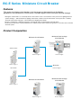
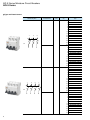
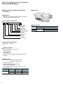
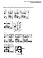
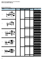
DISTRIBUTION
Miniature Circuit Breakers
BC-E Series
62D1-E-0088
BC-E Series Miniature Circuit Breaker
Features
This series of miniature circuit breaker is for the purpose of the protection of distribution
equipment in the residential or similar facility, to protect against short circuit and overload damage.
• Among the characteristics of overload protection, there are the Curve C characteristic for the protection of lighting electrical
systems having 5 ~ 10In instantaneous tripping characteristic, and the Curve D characteristic for the protection of ordinary
electrical system wires having 10 ~ 14In instantaneous tripping characteristic.
• ELCB is completed by combining a miniature circuit breaker with an earth leakage shunt trip device.
• As functional components can be installed such as auxiliary switch, alarm switch among others, it can monitor and control the
electrical system.
Product Composition
Miniature Circuit Breaker
Miniature Earth Leakage
Circuit Breaker
Refer to Page 4
Refer to Page 8
Auxiliary Switch
Refer to Page 11
Shunt trip
Refer to Page 11
Alarm Switch
Miniature Circuit Breaker
Miniature Earth Leakage
Circuit Breaker
Refer to Page 11
Refer to Page 12
Refer to Page 13
BC-E Series Miniature Circuit Breakers
BC63 Series Miniature Circuits Breaker----------------------------------------------- 4
BC32 and BC50 Series Miniature Earth Leakage Circuit Breaker-------------- 8
Optional accessories---------------------------------------------------------------------- 11
BC32 Series Miniature Circuit Breaker (1P+N)------------------------------------- 12
BC32 Series Miniature Earth Leakage Circuit Breaker (1P+N)---------------- 13
Wiring Method------------------------------------------------------------------------------ 14
Characteristic curves---------------------------------------------------------------------- 14
Temperature Compensation Table----------------------------------------------------- 15
3
BC-E Series Miniature Circuit Breakers
BC63 Series
BC63 Series Miniature Circuit Breaker
Standards
Application
• Curve C: Illumination distribution system
Curve D: Industrial distribution system
• Overload and short circuit protection
Specifications
•
•
•
•
Rated voltage: AC230/400V, 50/60Hz
Rated current: page 5-6
Mechanical life: 10000 times
Tripping characteristic: C: 5~10In
D: 10-14In
• Breaking capacity
Tripping
characteristic
Type number nomenclature
BC 63
E
1
C
G
–
1P
Rated current Rated operational
(A)
voltage (V)
Curve C
006
E
Curve D
Rated breaking
capacity (kA)
1~40
230/400
6
50, 63
230/400
4.5
1~40
230/400
4.5
Rated current
Ex. 006:6A
Number of poles:
1P, 2P, 3P, 4P
Standard type: G
Instantaneous tripping
characteristic
C:Curve C
D:Curve D
Designing code
Ampere frame
63: 63A
BC-E series MCB
Wiring Capacity
Rated current (A)
Wire size (mm2)
In≤63
25
Dimensions, mm
PP',1
(1
Standards and Certificates
• IEC 60898-1, GB 10963.1
• CE, CCC
Working Condition
0D[
Product Features
• With short circuit current limiting structure-high breaking
capacity of lated short circuit.
• Short-circuit and overload protection
• Screw clamp, shock-proof wiring terminals
• Numerous accessories available
• Modularization-random combination, series mating
• Standard TH35 mm IEC rail mounting
4
Ambient temperature: -35˚C to +70˚C
Altitude: ≤2000m
Air humidity: ≤95%
Pollution degree: II
A place where there should not be significant shock or
vibration
•
•
•
•
•
BC-E Series Miniature Circuit Breakers
BC63 Series
Type and Rated Current
Number of poles
Tripping
characteristics
Curve C
Width
(mm)
18
1
1P
Curve D
2
Curve C
1
3
2P
Curve D
2
4
36
Rated current
(A)
Type
1
BC63E1CG-1P001E
2
BC63E1CG-1P002E
3
BC63E1CG-1P003E
4
BC63E1CG-1P004E
5
BC63E1CG-1P005E
6
BC63E1CG-1P006E
10
BC63E1CG-1P010E
16
BC63E1CG-1P016E
20
BC63E1CG-1P020E
25
BC63E1CG-1P025E
32
BC63E1CG-1P032E
40
BC63E1CG-1P040E
50
BC63E1CG-1P050E
63
BC63E1CG-1P063E
1
BC63E1DG-1P001E
2
BC63E1DG-1P002E
3
BC63E1DG-1P003E
4
BC63E1DG-1P004E
5
BC63E1DG-1P005E
6
BC63E1DG-1P006E
10
BC63E1DG-1P010E
16
BC63E1DG-1P016E
20
BC63E1DG-1P020E
25
BC63E1DG-1P025E
32
BC63E1DG-1P032E
40
BC63E1DG-1P040E
1
BC63E1CG-2P001E
2
BC63E1CG-2P002E
3
BC63E1CG-2P003E
4
BC63E1CG-2P004E
5
BC63E1CG-2P005E
6
BC63E1CG-2P006E
10
BC63E1CG-2P010E
16
BC63E1CG-2P016E
20
BC63E1CG-2P020E
25
BC63E1CG-2P025E
32
BC63E1CG-2P032E
40
BC63E1CG-2P040E
50
BC63E1CG-2P050E
63
BC63E1CG-2P063E
1
BC63E1DG-2P001E
2
BC63E1DG-2P002E
3
BC63E1DG-2P003E
4
BC63E1DG-2P004E
5
BC63E1DG-2P005E
6
BC63E1DG-2P006E
10
BC63E1DG-2P010E
16
BC63E1DG-2P016E
20
BC63E1DG-2P020E
25
BC63E1DG-2P025E
32
BC63E1DG-2P032E
40
BC63E1DG-2P040E
5
BC-E Series Miniature Circuit Breakers
BC63 Series
Type and Rated Current
Tripping
characteristics
Number of poles
Curve C
1
3
Width
(mm)
54
5
3P
2
4
Curve D
6
Curve C
1
3
5
7
4P
2
6
4
6
8
Curve D
72
Rated current
(A)
Type
1
BC63E1CG-3P001E
2
BC63E1CG-3P002E
3
BC63E1CG-3P003E
4
BC63E1CG-3P004E
5
BC63E1CG-3P005E
6
BC63E1CG-3P006E
10
BC63E1CG-3P010E
16
BC63E1CG-3P016E
20
BC63E1CG-3P020E
25
BC63E1CG-3P025E
32
BC63E1CG-3P032E
40
BC63E1CG-3P040E
50
BC63E1CG-3P050E
63
BC63E1CG-3P063E
1
BC63E1DG-3P001E
2
BC63E1DG-3P002E
3
BC63E1DG-3P003E
4
BC63E1DG-3P004E
5
BC63E1DG-3P005E
6
BC63E1DG-3P006E
10
BC63E1DG-3P010E
16
BC63E1DG-3P016E
20
BC63E1DG-3P020E
25
BC63E1DG-3P025E
32
BC63E1DG-3P032E
40
BC63E1DG-3P040E
1
BC63E1CG-4P001E
2
BC63E1CG-4P002E
3
BC63E1CG-4P003E
4
BC63E1CG-4P004E
5
BC63E1CG-4P005E
6
BC63E1CG-4P006E
10
BC63E1CG-4P010E
16
BC63E1CG-4P016E
20
BC63E1CG-4P020E
25
BC63E1CG-4P025E
32
BC63E1CG-4P032E
40
BC63E1CG-4P040E
50
BC63E1CG-4P050E
63
BC63E1CG-4P063E
1
BC63E1DG-4P001E
2
BC63E1DG-4P002E
3
BC63E1DG-4P003E
4
BC63E1DG-4P004E
5
BC63E1DG-4P005E
6
BC63E1DG-4P006E
10
BC63E1DG-4P010E
16
BC63E1DG-4P016E
20
BC63E1DG-4P020E
25
BC63E1DG-4P025E
32
BC63E1DG-4P032E
40
BC63E1DG-4P040E
BC-E Series Miniature Circuit Breakers
BC63 Series
Precautions for the DC use of BC63 Series
Miniature Circuit Breaker
• Choose the rated current of the circuit breaker according to
the power of direct current circuit.
• DC rated voltage determines the number of cascades of
circuit breaker to use.
DC60V
One pole
DC125V Two poles
DC250V Four poles
• Such use does not have to be divided into positive and
negative and can be up and down into the line.
• In the above use condition, the estimated short circuit
current cannot exceed its rated service short circuit breaking
capacity.
Circuit breaker
model
Rated current
(A)
BC63
1A~63A
DC rated service short circuit
breaking capacity (kA)
60V
125V
250V
10(1P)
20(2P)
50(4P)
Wiring Schematics
Ex. 1
Ex. 2
+
- 60V
+
- 125V
BC63
1P
BC63
2P
Load
Load
Ex. 3
+
- 250V
BC63
4P
Load
7
BC-E Series Miniature Circuit Breakers
BC32 and BC50 Series
Miniature Earth Leakage Circuit Breaker
Standards
Appearance
Application
• Clip onto the right side of BC32E1, BC50E1 series MCB
protection against earth leakage faults.
Type number nomenclature
BC 32
E
1
C
L – 1N 006 B
E
Rated residual
operating current
B: 30mA
Rated current
Ex. 006: 6A
Number of poles
Residual current protection
Instantaneous tripping
characteristic
C: Curve C
Designing code
Ampere frame
32: 32A
50: 50A
BC-E series MCB
Standards and Certificates
• IEC 61009-1, GB 16917.1
• CCC
Working Condition
•
•
•
•
•
Ambient temperature: -5˚C to +40˚C
Altitude: ≤2000m
Air humidity: ≤95%
Pollution degree: II
A place where there should not be significant shock or
vibration
Specifications
• Rated voltage: AC230/400V(1PN, 2P) 50Hz
AC400V(3P, 3PN, 4P) 50Hz
• Rated current: page 10
• Rated residual operating current: 30mA
• Mechanical life: 20000 times
• Instantaneous tripping characteristic: curve C: 5-10In
• Breaking capacity
Tripping
characteristic
Curve C
8
Rated current Rated operational
(A)
voltage (V)
Rated breaking
capacity (kA)
1~40
230/400
6
50
230/400
4.5
Wiring Capacity
Rated
current (A)
In≤32
In≤50
Wire size (mm2)
Power
25
Load
10
25
BC-E Series Miniature Circuit Breakers
BC32 and BC50 Series
Dimensions, Miniature Earth Leakage Circuit Breaker, mm
Miniature earth leakage circuit breaker consists of miniature circuit breaker and earth leakage shunt trip.
BC32E1CL
18
1N
2P
3P
45
63
90
27
36
3N
99
54
27
36
54
45
4P
117
72
45
16
45.5
32
93
45
35mm DIN
EN50022
60
5.5
Max 72.5
BC50E1CL
2P
3P
3N
55
73
105
118
37
36
37
54
51
54
64
4P
136
64
16
45.5
35mm DIN
EN50022
32
72
93
45
18
1N
60
5.5
Max 72.5
9
BC-E Series Miniature Circuit Breakers
BC32 and BC50 Series
Type and Rated Current
Number of
poles
Tripping
characteristics
Wiring diagram
Curve C
Width (mm)
Miniature
Earth leakage
circuit breaker
shunt trip
18
27
N
1
T
1N
2 N
1 phase line + neutral line
37
36
1 3
27
T
2P
2 4
37
54
1
3
5
36
T
3P
2 4 6
51
54
45
N
T
1 3 5
3N
2 4 6 N
3 phase line + neutral line
64
72
45
T
1 3 5 7
4P
2 4 6 8
64
Rated current
(A)
1
2
3
4
5
6
10
16
20
25
32
40
50
1
2
3
4
5
6
10
16
20
25
32
40
50
1
2
3
4
5
6
10
16
20
25
32
40
50
1
2
3
4
5
6
10
16
20
25
32
40
50
1
2
3
4
5
6
10
16
20
25
32
40
50
Type
BC32E1CL-1N001BE
BC32E1CL-1N002BE
BC32E1CL-1N003BE
BC32E1CL-1N004BE
BC32E1CL-1N005BE
BC32E1CL-1N006BE
BC32E1CL-1N010BE
BC32E1CL-1N016BE
BC32E1CL-1N020BE
BC32E1CL-1N025BE
BC32E1CL-1N032BE
BC50E1CL-1N040BE
BC50E1CL-1N050BE
BC32E1CL-2P001BE
BC32E1CL-2P002BE
BC32E1CL-2P003BE
BC32E1CL-2P004BE
BC32E1CL-2P005BE
BC32E1CL-2P006BE
BC32E1CL-2P010BE
BC32E1CL-2P016BE
BC32E1CL-2P020BE
BC32E1CL-2P025BE
BC32E1CL-2P032BE
BC50E1CL-2P040BE
BC50E1CL-2P050BE
BC32E1CL-3P001BE
BC32E1CL-3P002BE
BC32E1CL-3P003BE
BC32E1CL-3P004BE
BC32E1CL-3P005BE
BC32E1CL-3P006BE
BC32E1CL-3P010BE
BC32E1CL-3P016BE
BC32E1CL-3P020BE
BC32E1CL-3P025BE
BC32E1CL-3P032BE
BC50E1CL-3P040BE
BC50E1CL-3P050BE
BC32E1CL-3N001BE
BC32E1CL-3N002BE
BC32E1CL-3N003BE
BC32E1CL-3N004BE
BC32E1CL-3N005BE
BC32E1CL-3N006BE
BC32E1CL-3N010BE
BC32E1CL-3N016BE
BC32E1CL-3N020BE
BC32E1CL-3N025BE
BC32E1CL-3N032BE
BC50E1CL-3N040BE
BC50E1CL-3N050BE
BC32E1CL-4P001BE
BC32E1CL-4P002BE
BC32E1CL-4P003BE
BC32E1CL-4P004BE
BC32E1CL-4P005BE
BC32E1CL-4P006BE
BC32E1CL-4P010BE
BC32E1CL-4P016BE
BC32E1CL-4P020BE
BC32E1CL-4P025BE
BC32E1CL-4P032BE
BC50E1CL-4P040BE
BC50E1CL-4P050BE
• The earth leakage shunt trip of our company is only supplied in conjunction with the miniature circuit breaker of our company and will not be supplied alone.
10
BC-E Series Miniature Circuit Breakers
Optional accessories
Accessories Standards
Auxiliary switch (W)
Type: BC9W1SA1-E
Application
• Linked to the left side of BC63 series MCB to indicate the OPEN or
CLOSED status of the associated breaker
Specifications
• Rated operating parameters
11
Voltage
Current
Voltage
Current
AC 230V
6A
AC 400V
3A
DC 24V
6A
DC 48V
2A
DC 125V
1A
DC 250V
0.4A
• Width (mm): 9
12
Notes:
After clipping on to BC63
Point 11 and 14 are connected when circuit is closed;
Point 11 and 12 are connected when circuit is open.
May be used in conjunction with two alarm switches or another auxiliary switch.
14
Alarm Switch (K)
Type: BC9K1SA1-E
Application
• Linked to the left side of BC63 series MCB, to indicate the OPEN or
CLOSED status of the associated breaker
Specifications
• Rated operating parameters
91
Voltage
Current
Voltage
Current
AC 230V
6A
AC 400V
3A
DC 24V
6A
DC 48V
2A
DC 125V
1A
DC 250V
0.4A
• Width (mm): 9
92
Notes:
After clipping on to BC63 MCB,
Point 91 and 92 are connected when circuit is closed;
Point 91 and 94 are connected when the breaker trips due to fault;
Point 91 and 92 are connected when the breaker trips by manual operation. Meanwhile,
point 91 and 94 are disconnected.
May be used in conjunction with two alarm switches.
94
Shunt trip (F+W)
Type: BC9FRA1-E, BC9FKA1-E
L or +
C2
Application
• Linked to the right side of BC63 series MCB
• Remote control
Specifications
• Control voltage
C1
12
14
MCB
open
MCB
closed
SB
N or - L1 L2
Standards and Certificates
• IEC 60947-5, GB 14048.5
• CCC
Type
Control voltage
BC9FRA1-E
AC230/400V
BC9FKA1-E
DC24/48V
• Width (mm): 18
Assembly methods
OFF
Wiring Capacity
• Single line: 2.5 mm2 Double line: 1.5 mm2
11
BC-E Series Miniature Circuit Breakers
BC32 Series Miniature Circuit Breaker (1P+N)
Miniature Circuit Breaker (1P+N)
Specifications
•
•
•
•
Application
• TT/TN-S grounding system
• Phase and neutral protection against short circuit and
overload
Rated voltage: AC230V, 50/60Hz
Mechanical life: 10000 times
Tripping characteristic: C: 5~10In
Breaking capacity: 4.5kA
Wiring Capacity
• ≤ 10 mm2
Type number nomenclature
BC 32
E
1
C
N – 1P 006 E
Dimensions, mm
Rated current
Ex.006: 6A
18
44
Number of poles: 1P
Neutral line type: N
Instantaneous tripping
characteristic
C: Curve C
Designing code
Ampere frame
45
77
35mm DIN
EN50022
32: 32A
BC-E series MCB
60
5.5
Max70.5
Standards and Certificates
• IEC 60898-1, GB 10963.1
• CCC
68.5
36
44
Working Condition
• Ambient temperature: -35˚C to +70˚C
• Altitude: ≤2000m
• Air humidity: ≤95%
45
77
35mm DIN
EN50022
Product Features
60
Max70.5
• Phase and neutral are both switched when circuit opens or
trips because of failure
• Neutral line connected early and disconnected late
• Screw clamp, shock-proof wiring terminals
• Standard TH35 mm IEC rail mounting
5.5
Type and Rated Current
Number of poles
Width (mm)
N 1
18
1P+N
N 2
12
Rated current (A)
Type
6
BC32E1CN-1P006E
10
BC32E1CN-1P010E
16
BC32E1CN-1P016E
20
BC32E1CN-1P020E
25
BC32E1CN-1P025E
32
BC32E1CN-1P032E
BC-E Series Miniature Circuit Breakers
BC32 Series Miniature Earth Leakage Circuit Breaker (1P+N)
Earth Leakage Circuit Breaker (1P+N)
18
Specifications
44
60
Wiring Capacity
Type number nomenclature
1
C
L
N
–
• ≤ 10 mm2
1P 006 E
Rated current
Ex.006: 6A
Number of poles: 1P
Neutral line type: N
Residual current protection
Instantaneous
tripping characteristic
C: Curve C
Designing code
Ampere frame
32: 32A
BC-E series MCB
Dimensions, mm
68.5
36
44
35mm DIN
EN50022
45
E
5.5
Max70.5
77
BC 32
35mm DIN
EN50022
45
Rated voltage: AC230V, 50Hz
Mechanical life: 10000 times
Tripping characteristic: C: 5~10In
Rated residual operating current: 30mA
Breaking capacity: 4.5kA
77
Application
• TT/TN-S grounding system
• Phase and neutral protection against short circuit and
overload
•
•
•
•
•
60
Max70.5
Standards and Certificates
5.5
• IEC 61009-1, GB 16917.1
• CCC
Working Condition
• Ambient temperature: -5ºC to +40ºC
• Altitude: ≤2000m
• Air humidity: ≤95%
Product Features
• Phase and neutral are both switched when circuit opens or
trips because of failure
• Neutral line connected early and disconnected late
• Convenient wiring
• Standard TH35 mm IEC rail mounting
Type and Rated Current
Number of poles
Width (mm)
1P+N
N 1
36
N 2
Rated current (A)
Rated residual operating
current (mA)
Type
6
BC32E1CLN-1P006E
10
BC32E1CLN-1P010E
16
20
30
BC32E1CLN-1P016E
BC32E1CLN-1P020E
25
BC32E1CLN-1P025E
32
BC32E1CLN-1P032E
13
BC-E Series Miniature Circuit Breakers
Wiring method/Characteristic Curves
Wiring Method
Use of phase line and neutral line series products in the TT / TN-S systems
Phase line and neutral line are required to be switched in the TT (three-phase four-wire system)/TN-S (three-phase five-wire
system) systems.
L1
L2
L3
N
TT
PE
Load
Load
Load
L1
L2
L3
N
PE
TN-S
Load
Load
Load
Characteristic Curves
BC32, BC50, BC63
• Curve C (5~10In)
• Curve D (10~14In)
180
120
180
120
60
40
60
40
20
20
Minute 10
Minute
6
4
2
2
Max. Value
20
10
6
4
2 Min. Value
Second 1
0.6
0.4
0.2
0.1
0.06
0.04
Max. Value
20
10
6
4
2
Min. Value
Second 1
Instantaneous
tripping characteristic
500~1000%
0.02
14
1
40
Operating time
Operating time
1
40
0.01
10
6
4
Instantaneous
tripping characteristic
1000~1400%
0.6
0.4
0.2
0.1
0.06
0.04
0.02
1
1.5 2
3 4 5 6 78 10 15 20 30 4050 60 80 100
Multiple of rated current
0.01
1
1.5 2
3 4 5 6 78 10 15 20 30 4050 60 80 100
Multiple of rated current
BC-E Series Miniature Circuit Breakers
Temperature Compensation Table
Temperature Compensation Table
Compensated
current(A)
Ambient temperature (C˚)
-35
Rated current(A)
1
3
6
10
16
20
25
32
40
50
63
1.27
3.89
7.70
13.89
20.78
25.67
32.21
41.04
51.63
64.92
83.48
-30
1.25
3.83
7.58
13.62
20.43
25.28
31.72
40.46
50.86
63.97
82.06
-25
1.23
3.76
7.46
13.35
20.08
24.88
31.22
39.82
50.04
62.92
80.64
-20
1.21
3.70
7.34
13.07
19.75
24.47
30.70
39.17
49.21
61.86
79.19
-15
1.19
3.64
7.21
12.81
19.40
24.06
30.18
38.51
48.37
60.77
77.72
-10
1.17
3.57
7.09
12.53
19.05
23.64
29.65
37.84
47.51
59.67
76.22
-5
1.15
3.50
6.96
12.23
18.70
23.22
29.10
37.15
46.63
58.54
74.70
0
1.13
3.44
6.83
11.93
18.33
22.78
28.55
36.47
45.74
57.40
73.14
5
1.10
3.37
6.70
11.63
17.96
22.34
27.98
35.75
44.83
56.23
71.54
10
1.08
3.30
6.56
11.33
17.58
21.89
27.41
35.03
43.90
55.05
69.91
15
1.06
3.22
6.42
11.01
17.20
21.43
26.82
34.30
42.95
53.81
68.24
20
1.05
3.14
6.27
10.67
16.80
20.96
26.22
33.54
41.98
52.56
66.53
25
1.02
3.06
6.14
10.34
16.40
20.47
25.61
32.77
40.99
51.28
64.78
30
1.00
3.00
6.00
10.00
16.00
20.00
25.00
32.00
40.00
50.00
63.00
35
0.97
2.92
5.84
9.63
15.35
19.47
24.33
31.17
38.93
47.82
60.11
40
0.94
2.84
5.68
9.24
15.11
18.95
23.67
30.34
37.85
46.24
58.19
45
0.91
2.76
5.52
8.85
14.66
18.42
23.00
29.48
36.75
44.81
56.21
50
0.89
2.67
5.36
8.45
14.20
17.87
22.28
28.60
35.61
43.33
54.16
55
0.86
2.58
5.19
8.01
13.71
17.30
21.56
27.69
34.43
41.81
52.03
60
0.83
2.49
5.01
7.55
13.21
16.71
20.80
26.75
33.21
40.23
49.81
65
0.80
2.38
4.83
7.06
12.70
16.10
20.02
25.78
31.95
38.58
47.50
70
0.77
2.27
4.64
6.55
12.15
15.47
19.21
24.77
30.63
35.77
43.05
Note: Ambient temperature means the set temperature within the circuit breaker distribution box or distribution panel.
The standard ambient temperature of 1A-63A circuit breaker is 30°C.
15
Catalog Disclaimer
The information contained in this catalog does not constitute an express or implied warranty of quality, any warranty of
merchantability of fitness for a particular purpose is hereby disclaimed.
Since the user's product information, specific use application, and conditions of use are all outside of Fuji Electric FA
Components & Systems'control, it shall be the responsibility of the user to determine the suitability of any of the
products mentioned for the user's application.
One Year Limited Warranty
The products identified in this catalog shall be sold pursuant to the terms and conditions identified in the
"Conditions of Sale" issued by Fuji Electric FA with each order confirmation.
Except to the extent otherwise provided for in the Conditions of Sale issued by Fuji Electric FA, Fuji Electric FA
warrants that the Fuji Electric FA products identified in this catalog shall be free from significant defects in materials and
workmanship provided the product has not been: 1) repaired or altered by others than Fuji Electric FA; 2) subjected to
negligence, accident, misuse, or damage by circumstances beyond Fuji Electric FA's control; 3) improperly operated,
maintained or stored; or 4) used in other than normal use or service. This warranty shall apply only to defects appearing
within one (1) year from the date of shipment by Fuji Electric FA, and in such case, only if such defects are reported
to Fuji Electric FA within thirty (30) days of discovery by purchaser. Such notice should be submitted in writing to Fuji
Electric FA at 5-7, Nihonbashi Odemma-cho, Chuo-ku, Tokyo, Japan. The sole and exclusive remedy with respected to
the above warranty whether such claim is based on warranty, contract, negligence, strict liability or any other theory,
is limited to the repair or replacement of such product or, at Fuji Electric FA's option reimbursement by Fuji Electric FA
of the purchase price paid to Fuji Electric FA for the particular product. Fuji Electric FA does not make any other
representations or warranties, whether oral or in writing, expressed or implied, including but not limited to any
warranty regarding merchantability or fitness for a particular purpose. Except as provided in the Conditions of
Sale, no agent or representative of Fuji Electric FA is authorized to modify the terms of this warranty in writing or orally.
In no event shall Fuji Electric FA be liable for special, indirect or consequential damages, including but not limited to,
loss of use of the product, other equipment, plant and power system which is installed with the product, loss of profits or
revenues, cost of capital, or claims against the purchaser or user of the product by its customers resulting from the use of
information, recommendations and descriptions contained herein. The purchaser agrees to pass on to its customers and
users, in writing at the time inquiries and orders are received by buyer, Fuji Electric FA's warranty as set forth above.
Safety Considerations
• Operate (keep) in the environment specified in the operating instructions and manual. High temperature, high humidity,
condensation, dust, corrosive gases, oil, organic solvents, excessive vibration or shock might cause electric shock, fire,
erratic operation or failure.
• For safe operation, before using the product read the instruction manual or user manual that comes with the product
carefully or consult the Fuji sales representative from which you purchased the product.
• Products introduced in this catalog have not been designed or manufactured for such applications in a system or
equipment that will affect human bodies or lives.
• Customers, who want to use the products introduced in this catalog for special systems or devices such as for atomicenergy control, aerospace use, medical use, passenger vehicle, and traffic control, are requested to consult with Fuji
Electric FA.
• Customers are requested to prepare safety measures when they apply the products introduced in this catalog to such
systems or facilities that will affect human lives or cause severe damage to property if the products become faulty.
• For safe operation, wiring should be conducted only by qualified engineers who have sufficient technical knowledge
about electrical work or wiring.
• Follow the regulations of industrial wastes when the product is to be discarded.
• For further questions, please contact your Fuji sales representative or Fuji Electric FA.
Safety Considerations
• Operate (keep) in the environment specified in the operating instructions and manual. High temperature, high humidity, condensation, dust,
corrosive gases, oil, organic solvents, excessive vibration or shock might cause electric shock, fire, erratic operation or failure.
• For safe operation, before using the product read the instruction manual or user manual that comes with the product carefully or consult the
Fuji sales representative from which you purchased the product.
• Products introduced in this catalog have not been designed or manufactured for such applications in a system or equipment that will affect
human bodies or lives.
• Customers, who want to use the products introduced in this catalog for special systems or devices such as for atomic-energy control,
aerospace use, medical use, passenger vehicle, and traffic control, are requested to consult with Fuji Electric FA.
• Customers are requested to prepare safety measures when they apply the products introduced in this catalog to such systems or facilities
that will affect human lives or cause severe damage to property if the products become faulty.
• For safe operation, wiring should be conducted only by qualified engineers who have sufficient technical knowledge about electrical work or
wiring.
• Follow the regulations of industrial wastes when the product is to be discarded.
• For further questions, please contact your Fuji sales representative or Fuji Electric FA.
5-7, Nihonbashi Odemma-cho, Chuo-ku, Tokyo, 103-0011, Japan
URL http://www.fujielectric.co.jp/fcs/eng
Information in this catalog is subject to change without notice.
2013-1 PDF FOLS 62D1-E-0088


![[U7.02.01] Opérateur LIRE_RESU](http://vs1.manualzilla.com/store/data/006356297_1-749ae76a42abe905de648234092ec94b-150x150.png)