1
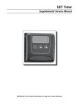
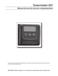
SE Timer
Supplemental Service Manual
IMPORTANT: Fill in Pertinent Information on Page 3 for Future Reference
Table of Contents
Job Specification Sheet.......................................................................................................................................... 3
Timer Operation...................................................................................................................................................... 4
Master Programming Mode Flow Chart................................................................................................................. 7
Master Programming Mode.................................................................................................................................... 9
2510/2750/2850 Timer Assembly......................................................................................................................... 13
9000/9100/9500 Twin Tank Timer Assembly........................................................................................................ 14
3/4” Brass Paddle Meter Assembly (for 2500 Econominder)............................................................................... 15
3/4” Plastic Paddle Meter Assembly (for 6600 Downflow).................................................................................... 16
3/4” Plastic Turbine Meter Assembly.................................................................................................................... 17
1” Brass Paddle Meter Assembly......................................................................................................................... 18
Inline Plastic Meter Assembly............................................................................................................................... 19
1 1/2” Brass Paddle Meter Assembly................................................................................................................... 20
3/4”, 1”, or 1 1/2” Paddle Wheel Meter Cap Assembly......................................................................................... 21
2510SE Wiring Diagram....................................................................................................................................... 22
2750SE/2850SE Wiring Diagram......................................................................................................................... 23
9000/9100/9500 Wiring Diagram.......................................................................................................................... 24
Troubleshooting - Timer........................................................................................................................................ 25
Service Assemblies.............................................................................................................................................. 26
IMPORTANT PLEASE READ:
•
The information, specifications and illustrations in this manual are based on the latest information available at the time of
printing. The manufacturer reserves the right to make changes at any time without notice.
•
This manual is intended as a guide for service of the valve only. System installation requires information from a number of
suppliers not known at the time of manufacture. This product should be installed by a plumbing professional.
•
This unit is designed to be installed on potable water systems only.
•
This product must be installed in compliance with all state and municipal plumbing and electrical codes. Permits may be
required at the time of installation.
•
If daytime operating pressure exceeds 80 psi, nighttime pressures may exceed pressure limits. A pressure reducing valve must
be installed.
•
Do not install the unit where temperatures may drop below 32°F (0°C) or above 125°F (52°C).
•
Do not place the unit in direct sunlight. Black units will absorb radiant heat increasing internal temperatures.
•
Do not strike the valve or any of the components.
•
Warranty of this product extends to manufacturing defects. Misapplication of this product may result in failure to properly
condition water, or damage to product.
•
A prefilter should be used on installations in which free solids are present.
•
In some applications local municipalities treat water with Chloramines. High Chloramine levels may damage valve components.
•
Correct and constant voltage must be supplied to the control valve to maintain proper function.
Job Specification Sheet
Please Circle and/or Fill in the Appropriate Data for Future Reference:
Programming Mode:
Volume Remaining __________ Gallons ___________ Liters ______Cubic Meters
Regeneration Time Delayed __________ AM or PM or Immediate
Regeneration Day Override (A) Off or Every _________ Days
Master Programming Mode:
Display Format (U)
Regeneration Type (T)
Regeneration Cycle Step #1
Regeneration Cycle Step #2
Regeneration Cycle Step #3
Regeneration Cycle Step #4
Regeneration Cycle Step #5
1. U.S. Gallons 2. Liter
1. Time Clock 2. Meter Immediate
_______________ Minutes
Off or __________ Minutes
Off or __________ Minutes
Off or __________ Minutes
Off or __________ Minutes
Flow Meter Pulses (F)
Valve Type (O)
Line Frequency
_________ Pulses
1. 2510, 2750, 2850
50 Hz or 60 Hz
3. Cubic Meters
3. Meter Delayed
2. 9000, 9100, 9500
Page Timer Operation
In normal operation the Time Of Day display alternates with the Volume Remaining and Tank in Service displays
(9000, 9100, 9500 SE Timer only). As treated water is used, the Volume Remaining display counts down (in
gallons) from a maximum value to zero or (----). Once this occurs a regeneration cycle initiates immediately or
delayed to the set Regeneration Time. Water flow through the valve is indicated by the flashing Flow Dot Indicator.
Set Time of Day
When the valve is In Service, press either the Set Up or Set Down button once to adjust the Time Of Day by one
digit. Press and hold to adjust by several digits.
Start an Extra Regeneration Cycle
Press the Extra Regeneration button to start an extra regeneration tonight. Press and hold the Extra
Regeneration button for 5 seconds to start an Extra Regeneration immediately.
Page Timer Operation
Set Control Programming
1. Press and hold both the Set Up and Set Down buttons for 5 seconds.
2. Set the Treated Water Capacity. Using the Set Up or Set Down buttons, set the amount of treated water to
flow through the unit before a regeneration is required.
3. Press the Extra Regeneration button.
4. Set the Regeneration Time. Use the Set Up or Set Down buttons to set the desired time of day for
regeneration to occur.
5. Press the Extra Regeneration button.
6. Set Regeneration Day Override. Use the Set Up or Set Down buttons to set the maximum number of days
before a regeneration cycle must occur.
7. Press the Extra Regeneration button to exit the program.*
*NOTE: If setting up the system for the first time, perform the following Fast Cycle Regeneration:
1.
2.
3.
4.
5.
6.
7.
Press the Extra Regeneration button for 5 seconds to force an extra regeneration immediately.
Once the valve reaches Regen Step #1, let water run to the drain for approximately 5 minutes.
Press the Extra Regeneration button once to advance valve to Regeneration Step #2.
Press the Extra Regeneration button once to advance valve to Regeneration Step #3 (if active).
Press the Extra Regeneration button once to advance valve to Regeneration Step #4 (if active).
Press the Extra Regeneration button once to advance valve to Regeneration Step #5 (if active)
Press the Extra Regeneration button once more to advance the valve back to service.
Page Timer Operation
Immediate Regeneration Valves With Days Between Regeneration Override Set
When the valve reaches its set Days Since Regeneration Override value, a regeneration cycle initiates
immediately. This event occurs regardless of the Volume Remaining display having reached zero gallons.
Delayed Regeneration Valves With Days Between Regeneration Override Set
When the valve reaches its set Days Since Regeneration Override value, a regeneration cycle initiates at the
preset regeneration time. This event occurs regardless of the Volume Remaining display having reached zero
gallons.
Control Operation During Regeneration
During regeneration, the control displays a special regeneration display. In this display, the control shows the
current regeneration step number the valve is advancing to, or has reached, and the time remaining in that step.
The step number that displays flashes until the valve completes driving to this regeneration step position. Once all
regeneration steps are complete the valve returns to service and resumes normal operation.
Example:
Pressing the Extra Cycle button during a regeneration cycle immediately advances the valve to the next cycle
step position and resumes normal step timing.
Control Operation During Programming
The control only enters the Program Mode with the valve in service. While in the Program Mode, the control
continues to operate normally monitoring water usage and keeping all displays up to date. Control programming is
stored in memory permanently, eliminating the need for battery backup power.
Control Operation During A Power Failure
During a power failure all control displays and programming are stored for use upon power re-application. The
control retains these values for years, if necessary, without loss. The control is fully inoperative and any calls for
regeneration are delayed. Upon reapplication of power, the control resumes normal operation from the point that it
was interrupted. An indication that a power outage has occurred is an inaccurate Time Of Day display.
Page Master Programming Mode Flow Chart
NOTE:
1. Set Time of Day display to 12:01 P.M.
2. Press and hold the Set Up and
Set Down buttons for 5 seconds.
3. Press the Extra Cycle button once
per display until all displays are viewed
and normal operation is resumed.
4. Option setting displays may be changed
as required by pressing either the
Set Up or Set Down button.
5. Depending on current programming,
certain displays will not be able to
be viewed or set.
6. Reference the programming instructions
for a complete list of available settings.
CAUTION: Before entering Master Programming, please contact your local professional water dealer.
Page Master Programming Mode Flow Chart
CAUTION: Before entering Master Programming, please contact your local professional water dealer.
Page Master Programming Mode
When the Master Programming Mode is entered, all available option setting displays may be viewed and set as
needed. Depending on current option settings, some displays cannot be viewed or set.
Entering Master Programming Mode
Set the Time Of Day display to 12:01 P.M. Press and hold the Set Up and Set Down buttons together until the
Program Dot turns on (about 5 seconds). Depending on current option settings, some displays cannot be viewed
or set.
Exiting Master Programming Mode
Press the Extra Cycle button once per display until all are viewed. The Program Mode is exited and normal
operation resumes.
Resetting Permanent Programming Memory
There are two ways to reset the timer:
a. Press and hold the Set Up and Set Down buttons for 25 seconds until the Time Of Day display resets to.
12:00 P.M. All option settings are reset to default values. Control programming must be reset as.
necessary.
b. Press and hold the Extra Cycle button while applying power. Release the Extra Cycle button. When the .
timer powers up, “P3.0” (the software version) will be displayed for 2 seconds on the LED display.
1. Display Format (Display Code U)
Press the Extra Cycle button. This display is used to set the desired display format. This option setting is
identified by the “U” in the first digit. There are two possible settings:
US Format uses gallons for volume with a 12 hour timekeeping format. Regeneration timing is in minutes..
Use the Set Up and Set Down buttons to adjust this value.
Example: [U - - I]
Metric Format uses liters for volume and a 24 hour timekeeping format. Regeneration timing is in tenths of
minutes. Use the Set Up and Set Down buttons to adjust this value.
Example: [U - - 2]
Cubic Metric Format uses cubic meters for volume and a 24 hour timekeeping format. Regeneration .
timing in tenths of minutes. Use the Set Up and Set Down buttons to adjust this value.
Example: [U - - 4]
CAUTION: Before entering Master Programming, please contact your local professional water dealer.
Page Master Programming Mode
2. Regeneration Type (Display Code 7)
Press the Extra Cycle button. Use this display to set the Regeneration Type. This option setting is identified
by the number “7” in the first digit. There are three possible settings:
Timeclock Delayed
The control determines the day that a regeneration is required by the Regeneration Day Override setting (A).
Once this day is reached, a regeneration cycle starts at the set Regeneration Time..
NOTE: The display will alternate between the “Time of Day” and “Days to Regeneration” when
Timeclock Delayed is selected.
Example: [7 - - I]
Meter Immediate
The control determines that regeneration is required when the available volume of treated water drops to
zero. Regeneration begins immediately.
Example: [7 - - 2] This setting is typically used on the Twin Tank Control Valves.
Meter Delayed
The control determines that regeneration is required when the available volume of treated water drops to
zero. Regeneration begins immediately at the set regeneration time. Use the Set Up and Set Down buttons
to adjust this value.
Example: [7 - - 3]
3. Volume Remaining (No Display Code)
Press the Extra Cycle button. Use this display to set the amount of water (gallons/liters/cubic meters) that
can be treated by the unit before a regeneration cycle is required. With Meter Delayed Regeneration Type
set, it is necessary for the programmer to determine a reserve capacity and subtract that value from the
calculated full capacity of the unit. This display cannot be viewed with Timeclock Regeneration Type set.
Use the Set Up and Set Down buttons to adjust this value.
Range = t10.0 - t60.0 = 10,000 - 60,000 gallons
Range = t10.0 - t60.0 = 10,000 - 60,000 liters
Range = t10.0 - t60.0 = 10,000 - 60,000 cubic meters
4. Regeneration Time (Clock Display Without a Flashing Colon)
Press the Extra Cycle button. The next display that appears is the option setting for Regeneration Time.
It is identified by a clock display without a flashing colon. Set the desired time of day that a regeneration may
occur. This display cannot be viewed with Meter Immediate Regeneration Type set. Use the Set Up and
Set Down buttons to adjust this value.
Range = Anytime
Example: 2 o’clock A.M. Regeneration Time — [ 2: 0 0] (A.M. Indicator Dot On)
CAUTION: Before entering Master Programming, please contact your local professional water dealer.
Page 10
Master Programming Mode
5. Regeneration Day Override (Display Code A)
Press the Extra Cycle button. The next display that appears is the option setting for Regeneration Time.
It is identified by a clock display without a flashing colon. Set the desired time of day that a regeneration may
occur. This display cannot be viewed with Meter Immediate Regeneration Type set. Use the Set Up and Set
Down buttons to adjust this value.
— With Timeclock or Meter Delayed Regeneration Type selected, regeneration begins at the set
regeneration time.
— With Meter Immediate Regeneration Type selected, regeneration begins at the same time of day that the
last regeneration cycle was initiated. An OFF setting cancels this feature with all regeneration types.
except Timeclock Regeneration where it must be used. Use the Set Up and Set Down buttons to adjust
this value.
Range = 1-99 (Timeclock Delayed)
Range = OFF, 1-99 (All Meter Regeneration Types)
Example: Override every 7 days — [A - - 7]
Cancel setting — [A O F F] (Meter Immediate or Delayed Regeneration Types Only)
6. Regeneration Cycle Step Programming (Display Code 1-5)
Press the Extra Cycle button. The next 2-6 displays that appear are part of a series of option settings
used to program the Regeneration Cycle. Each display is used to set in minutes (or tenths of minutes for.
Metric). A step # turns on for the regeneration cycle step being programmed.
Range = OFF, 100-199 minutes (US Format)
Range = OFF, 100-199 minutes (Metric Format)
— Skip regeneration steps by setting the display to 0
— End a regeneration cycle by setting the step # after the last active step to OFF, as shown below:
Example: Regeneration Cycle Step #1, 8 minutes — [I - - 8] (US Format)
Regeneration Cycle Step #2, skipped — [2 - - 0] (US Format)
Regeneration Cycle Step #3, 8.5 minutes — [3 - 8.5] (Both Metric Formats)
Regeneration Cycle Step #4, cancelled — [4 O F F] (All Format)
— Press the Extra Cycle button once per display to advance through Regeneration Cycle Step
Programming.
— Use the Set Up and Set Down buttons to adjust this value.
CAUTION: Before entering Master Programming, please contact your local professional water dealer.
Page 11
Master Programming Mode
7. Flow Meter Size (Display Code F)
Press the Extra Cycle button. The next display sets the flow meter size. Use this display to set the proper
amount of pulses generated by the flow meter for each gallon of liter of water flow. This setting cannot be
viewed with Timeclock Regeneration Type selected.
Range = 1-999 pulses (US Format)
Range = .1-99.9 pulses (Metric Format)
Examples:
[F126]
3/4” Turbine Flow Meter used with the 2510SE (US Format)
[ F 3 3.2 ]
3/4” Turbine Flow Meter used with the 2510SE (Metric Format)
[F133]
3/4” Turbine Flow Meter used with the 9000SE (US Format)
[ F 3 5.1 ]
3/4” Turbine Flow Meter used with the 9000SE (Metric Format)
[F-20]
3/4” Paddle Wheel Flow Meter (US Format)
[ F - 5.3 ]
3/4” Paddle Wheel Flow Meter (Metric Format)
[F--8]
1.0” Paddle Wheel Flow Meter (US Format)
[ F - 2.1 ]
1.0” Paddle Wheel Flow Meter (Metric Format)
[F--4]
1-1/2” Paddle Wheel Flow Meter (US Format)
[ F 1.0 ]
1-1/2” Paddle Wheel Flow Meter (Metric Format)
[ F 80.0 ]
1” & 1-1/2” Inline Meter (US Format)
[ F 21.1 ]
1” & 1-1/2” Inline Meter (Metric Format)
— Use the Set Up and Set Down buttons to adjust this value.
8. Valve Type (Display Code o)
— Press the Extra Cycle button. Use this display to set the type of valve used with the control. This option
setting is identified by the letter “o” in the first digit. When #2 is selected, the current Tank # in Service
must be entered in the next display.
Example:
[o - - I] 2510, 2750 or 2850 Single Tank Valve Operation.
[o - - 2] 9000, 9100 or 9500 Twin Tanks Valve Operation.
[o - U I] Unit #1 Tank in Service. (viewed only when set to [o - - 2]
— Use the Set Up and Set Down buttons to adjust this value.
9. Line Frequency (Display Code LF)
—
—
—
Press the Extra Cycle button. Use this display to set the frequency of the power applied to the control.
When properly set, all timekeeping functions remain accurate. This option setting is identified by the
letters “LF” in the first two digits. There are two possible selections.
Example:
[L F 5 0] 50Hz Line Frequency Operation.
Example:
[L F 6 0] 60Hz Line Frequency Operation.
Use the Set Up and Set Down buttons to adjust this value.
Press the Extra Cycle button once more to exit this programming mode.
CAUTION: Before entering Master Programming, please contact your local professional water dealer.
Page 12
2510/2750/2850 Timer Assembly
Item No.
Quantity
Part No.
Description
1.................... 2..................... 11384.......................Screw, Phil, 6-32 x 1/4
2.................... 1..................... 13881.......................Bracket, Hinge Timer
3.................... 1..................... 14265.......................Clip, Spring
4.................... 3..................... 13296.......................Screw, Hex Wsh, 6-20 x 1/2
5.................... 1..................... 27172.......................Stand-Off, Timer, 2510SE, 2750SE
6.................... 2..................... 11384.......................Screw, Phil, 6-32 x 1/4
7.................... 1..................... 17749-00..................Relay, 24VAC, SPDT
8.................... 1..................... 27168.......................Bracket, Timer, 2510SE/2750SE
9.................... 1..................... 40429.......................Harness, SE, Designer/Environmental
10.................. 1..................... 61464.......................Timer, SE, 2510/2750/9000, DF
11.................. 1..................... 21363.......................Screw, Hex Hd, M4 x 12 mm
12.................. 1..................... 19697-01..................Label, Display, 5600SE
12A............... 1..................... 27793.......................Label, Front, SE, D/F, Pictogram
13.................. 1..................... 19471-02..................Cover, Front Panel, 5600SE, Black
14.................. 1..................... 40376.......................Button, Conductive Rubber
15.................. 1..................... 19889.......................Housing, Circuit Board
For Assembly Numbers, See the Back of this Manual
Page 13
9000/9100/9500 Twin Tank Timer Assembly
Item No.
Quantity
Part No.
Description
1.................... 1..................... 13881.......................Bracket, Hinge Timer
2.................... 2..................... 11384.......................Screw, Phil, 6-32 x 1/4
3.................... 2..................... 13296.......................Screw, Hex Wsh, 6-20 x 1/2
4.................... 1..................... 41233.......................Bracket, Mounting, 9000SE Timer
5.................... 1..................... 14265.......................Clip, Spring
6.................... 1..................... 26983.......................Stand-Off, Timer, 9000SE, FE
7.................... 1..................... 61464.......................Timer, SE, 2510/2750/9000, D/F
8.................... 1..................... 19474-01..................Harness, Power, 8500SE/4200SE
9.................... 1..................... 19697-01..................Label, Display, 5600SE
9A................. 1..................... 27793.......................Label, Front, SE, D/F, Pictogram
10.................. 1..................... 19471-02..................Cover, Front Panel, 5600SE, Black
11.................. 1..................... 40376.......................Button, Conductive Rubber
12.................. 1..................... 19889.......................Housing, Circuit Board
For Assembly Numbers, See the Back of this Manual
Page 14
3/4” Brass Paddle Meter Assembly
Item No.
Quantity
Part No.
Description
1.................... 1..................... 11206.......................Gasket, Fitting
2.................... 1..................... 13942.......................Retainer, Nut
3.................... 1..................... 11207.......................Nut, Special, QC
4.................... 1..................... 13906.......................Body, Meter, 3/4”
5.................... 1..................... 13509.......................Impeller, Meter
13509-01..................Impeller, Celcon
6.................... 1..................... 13847.......................O-ring, -137 Std/560CD, Meter
7.................... 1..................... 14716.......................Meter Cap Assy, ET/NT
8.................... 1..................... 12473.......................Screw, Hex Wsh, 10-24 x 5/8
Not Shown........................... 19121-08..................Meter Cable Assy, NT, 35” w/Connector
19121-09..................Meter Cable Assy, NT, 99.5” w/Connector
19121-10..................Meter Cable Assy, NT, 303.5” w/Connector
For Assembly Numbers, See the Back of this Manual
Page 15
3/4” Plastic Paddle Meter Assembly
Item No.
Quantity
Part No.
Description
1...................4.................... 12473.......................Screw, Hex Wsh, 10-24 x 5/8
2...................1.................... 14716.......................Meter Cap Assy, Elec, Plas, Pdl
3...................1.................... 13847.......................O-ring, -137, Std/560CD, Meter
4...................1.................... 13509.......................Impeller, Meter
5...................4.................... 13314.......................Screw, Slot Ind Hex, 8-18 x .60
6...................4.................... 13255.......................Clip, Mounting
7...................1.................... 13821.......................Body, Meter, 5600
8...................4.................... 13305.......................O-ring, -119
9...................1.................... 14613.......................Flow Straightener
For Assembly Numbers, See the Back of this Manual
Page 16
3/4” Plastic Turbine Meter Assembly
Item No.
Quantity
Part No.
Description
1.................... 1..................... 19791-01..................Meter Cable Assy, Turbine/SE
2.................... 2..................... 19569.......................Clip, Flow Meter
3.................... 2..................... 13314.......................Screw, Slot Ind Hex, 8-18 x .60
For Assembly Numbers, See the Back of this Manual
Page 17
1” Brass Paddle Meter Assembly
Item No.
Quantity
Part No.
Description
1.................... 1..................... 14959.......................Body, Meter, 2750
2.................... 1..................... 13882.......................Post, Meter Impeller
3.................... 1..................... 13509.......................Impeller, Meter
4.................... 1..................... 13847.......................O-ring, -137, Std/560CD, Meter
5.................... 1..................... 14716.......................Meter Cap Assy, ET/NT
6.................... 4..................... 12112.......................Screw, Hex Hd Mach, 10-24 x 1/2
7.................... 1..................... 14960.......................Flow Straightener, 1”
8.................... 1..................... 13287.......................O-ring, -123
9.................... 1..................... 14961.......................Fitting, 1” Quick Connector
10.................. 1..................... 14962.......................Nut, 1” Meter, Q/C
For Assembly Numbers, See the Back of this Manual
Page 18
Inline Plastic Meter Assembly
Item No.
Quantity
Part No.
Description
1.................... 1..................... 17542.......................Flow Straightener
2.................... 2..................... 40576.......................Clip, H, Plastic, 7000
3.................... 1..................... 40577.......................Turbine Meter Assy, 7000
4.................... 1..................... 41555.......................Body, Remote Meter
5.................... 2..................... 40951.......................O-ring, -220
6.................... 2..................... 40563.......................Connector, 1” NPT, 7000
7.................... 2..................... 40563-10..................Connector, 1” BSP, 7000
8.................... 2..................... 40565.......................Connector, 1 1/4” NPT, 7000
9.................... 2..................... 40565-10..................Connector, 1 1/4” BSP, 7000
10.................. 2..................... 41242.......................Connector, 1” & 1 1/4” Sweat
11.................. 2..................... 41243.......................Connector, 1 1/4 & 1 1/2” Sweat
12.................. 2..................... 41596.......................Connector, Brass, 1” NPT
13.................. 2..................... 41596-10..................Connector, Brass, 1” BSP
14.................. 2..................... 41597.......................Connector, Brass, 1 1/2” NPT
15.................. 2..................... 41597-10..................Connector, Brass, 1 1/2” BSP
For Assembly Numbers, See the Back of this Manual
Page 19
1 1/2” Brass Paddle Meter Assembly
Item No.
Quantity
Part No.
Description
1.................... 1..................... 17569.......................Body, Meter, 2850/9500
2.................... 1..................... 13882.......................Post, Meter Impeller
3.................... 1..................... 13509.......................Impeller, Meter
4.................... 1..................... 13847.......................O-ring, -137, Std/560CD, Meter
5.................... 1..................... 14716.......................Meter Cap Assy, ET/NT
6.................... 4..................... 12112.......................Screw, Hex Hd Mach, 10-24 x 1/2
7.................... 1..................... 17542.......................Flow Straightener, 1 1/2”
8.................... 1..................... 12733.......................O-ring, -132
9.................... 1..................... 17544.......................Fitting, 1 1/2” Quick Connector
10.................. 1..................... 17543.......................Nut, 1 1/2”, QC
For Assembly Numbers, See the Back of this Manual
Page 20
3/4”, 1” or 1 1/2” Paddle Wheel Meter Cap Assembly
Item No.
Quantity
Part No.
Description
1.................... 1..................... 14716.......................Meter Cap Assy, ET/NT
2.................... 1..................... 19121-01..................Meter Cable Assy, SE, Paddle 6600/6700
3.................... 1..................... 13847.......................O-ring, -137, Std/560CD, Meter
4.................... 1..................... 17798.......................Screw, Slot Hex Wsh Hd
For Assembly Numbers, See the Back of this Manual
Page 21
40528_REVD
2510SE Wiring Diagram
Page 22
40529_REVD
2750SE/2850SE Wiring Diagram
Page 23
40530_REVC
9000/9100/9500 Wiring Diagram
Page 24
Troubleshooting - Timer
Error Codes
Note: Error codes appear on the In Service display.
Error Code
Probable Cause
Recover and Resetting
[Err 0]
Drive motor is stalled.
[Err 1]
Drive motor is running
continuously.
Unplug the unit from the power source. When
power is restored to the unit, the .
Err _ display code clears. If the condition
causing the error has not been resolved the
Err _ code reappears in the four digit display.
Do not attempt to troubleshoot this problem
any further.
[Err 2]
There have been more than 99
days since the last regeneration.
Regeneration must occur for the unit to
recover, the display to clear and the valve to
function normally.
Page 25
Service Assemblies
Meter:
60086-50......... Meter Assy, 3/4”, Electronic 2510/6600/6700
60613.............. Meter Assy, 2750 Electronic 1”
60613-20......... Meter Assy, 2750, Electronic 1” BSP/Metric
60613NP......... Meter Assy, 2750, Electronic 1” Nickel Plated
60614.............. Meter Assy, 2850/9500, Electronic 1 1/2” Meter
60614NP......... Meter Assy, 2850/9500, Electronic 1 1/2” Meter, NP
60618.............. Meter Assy, Electronic, 3/4”
60619-20......... Meter Assy, 1 1/2” Elect BSP/Metric
60626.............. Meter Assy, Turbine, Electronic 3/4” wit Clips and Screws
60626-01......... Meter Assy, Turbine, ET 3/4” w/Clips, Screws, Mtr/Cable
61560-01......... Meter Assy, In-Line, w/1” NPT Plastic Connector
61560-02......... Meter Assy, In-Line, w/1” BSP Plastic Connector
61560-07......... Meter Assy, In-Line, w/1” NPT Brass Connector
61560-08......... Meter Assy, In-Line, w/1” BSP Brass Connector
61560-05......... Meter Assy, In-Line, w/1” I.D. & 1 1/4” O.D. Sweat Connector
61560-09......... Meter Assy, In-Line, w/ 1 1/2” NPT Brass Connector
61560-10......... Meter Assy, In-Line, w/ 1 1/2” BSP Brass Connector
Page 26
Notes
Page 27
P/N 40608
Rev. F