1
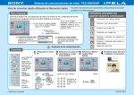
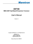
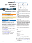
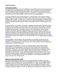
DS150
Digital Depth Sounder
Owner’s Manual
Marine Division of Vertex Standard
LIMITED WARRANTY
STANDARD HORIZON MARINE DIVISION OF VERTEX STANDARD warrants to the original purchaser
that each new Marine Product manufactured and/or supplied by STANDARD HORIZON will be free from
defects in materials and workmanship under conditions of normal use and service for a period of one
(1) year from the date of delivery to the Purchaser. STANDARD HORIZON’s liability under this
warranty shall be limited to repair or replacement of the defective product, at STANDARD HORIZON’s
option, under no circumstances shall STANDARD HORIZON be liable for consequential, incidental, or
other damages arising out of or in any way connected with a failure of the product to perform as set forth
herein.
In the event of a defect, malfunction, or failure of the product to conform to specifications during the
one-year warranty period, STANDARD HORIZON will repair or replace, at its option and without charge
to the Purchaser, the product which upon examination by STANDARD HORIZON shall appear to be
defective or not up to factory specifications. To obtain warranty service, the defective product must be
returned to STANDARD HORIZON together with proof of the date of purchase. The Purchaser must pay
any transportation expenses in returning the product to STANDARD HORIZON. STANDARD HORIZON
will examine the product and respond to the Purchaser in approximately four (4) weeks from date of
receipt of the product claimed to be defective.
This limited warranty does not extend to any product which has been subjected to misuse, neglect,
accident, improper installation, or subject to use in violation of the maintenance or operating instructions,
if any, furnished by STANDARD HORIZON, nor does this warranty extend to products on which the
serial number has been removed, defaced, or changed. STANDARD HORIZON reserves the right to
make changes or improvements to its products without notice during subsequent production without
incurring the obligation to install such changes or improvements on previously manufactured or sold
products.
To receive warranty service, the Purchaser must deliver the product, transportation and insurance
prepaid, to STANDARD HORIZON Marine Division of Vertex Standard, 115 North Wright Brothers
Dr. Salt Lake City, Utah 84116-2838. Include proof of purchase and date of purchase. STANDARD
HORIZON will return the Product to the Purchaser freight prepaid.
Some states do not allow limitations on the duration of the warranty or exclusions or limitations of
incidental or consequential damages so these limitations or exclusions may not apply to you. This
warranty gives you specific legal rights, which may vary from state to state.
Lifetime Flat Rate Service Program: For the original Purchaser only, for the lifetime of the unit,
STANDARD HORIZON will repair the unit to original specifications.
Note: The flat rate amount is payable by the Purchaser only if STANDARD HORIZON determines that
a repair is needed. After the repair, a 90-day warranty will be in effect from the date of return of the unit
to the Purchaser.
Owner’s Records
Model
Serial number
Purchase date
Dealer
Contents
1 General Information ............................................................................................ 4
1.1 Introduction ................................................................................................. 4
2 Controls and connections .................................................................................. 4
1.2 Front panel ................................................................................................. 4
1.3 Rear panel .................................................................................................. 4
3 Accessories ........................................................................................................ 5
3.1 Optional ...................................................................................................... 5
3.2 Replacement Parts .................................................................................... 5
4 Installation ........................................................................................................... 5
4.1 Instrument Installation ............................................................................... 5
4.1.1 Location .............................................................................................................. 5
4.1.2 Mounting ............................................................................................................. 5
4.1.3 Wiring Connection .............................................................................................. 6
4.1.4 Multiple Instruments ........................................................................................... 6
4.2 Transducer Installation .............................................................................. 7
4.2.1 In-Hull Installation ................................................................................................ 7
5 Operation ............................................................................................................ 7
5.1 Primary Functions ...................................................................................... 7
5.1.1 Select Units ........................................................................................................ 7
5.1.3 Setting Alarms .................................................................................................... 8
5.1.3.1 Set Shallow Alarm .......................................................................................... 8
5.1.3.2 Set Deep Alarm ............................................................................................... 8
5.1.4 Depth Alarm On / Off ......................................................................................... 8
5.2 Secondary Functions ................................................................................. 8
5.2.1 Set Display Dampening ...................................................................................... 8
5.2.2 Keel Offset ......................................................................................................... 9
5.2.3 Turbulence Setting ............................................................................................. 9
5.2.4 Simulation Mode ................................................................................................. 9
5.3 Microprocessor Reset ............................................................................. 10
6 Maintenance ...................................................................................................... 10
7 Specifications ................................................................................................... 11
8 Troubleshooting ............................................................................................... 11
DS150 User Manual
Owner’s Manual
Page 3
1 General Information
Note: Please familiarize yourself with the entire manual and transducer installation guide before
attempting installation.
1.1 Introduction
1.2 Front panel
The DS150 is a high quality digital depth sounder. It
mounts into a 1¼ inch diameter instrument hole on
the bulkhead.
The front panel includes a large 3 1/2-digit LCD and
three-button keypad. The keypad uses both tactile
and audible feedback to indicate when a key is
pressed. All functions are controlled entirely by
these three keys.
Features include depth readings from 3 to 400 feet
(equivalent meters or fathoms can be selected),
adjustable deep and shallow alarms with audible
alert, and waterproof front panel that can withstand
direct water spray. The unit will display “--” if the
depth is below 3 feet, above 400 feet, or if the
transducer signal is interrupted by cavitation.
1.3 Rear panel
The rear panel contains an RCA phono connector
for connection to the transducer. It also contains
red and black wires for connection to the power
supply and a blue wire for NMEA output.
Included:
•
•
•
•
Owners manual
DS150 Digital instrument
DS150 Panel Gasket
DC150 Dust cover
2 Controls and connections
Display is backlit for
Night Operation
Depth is increasing
Indicates alarm is on
Depth is decreasing
Deep Alarm
Set/Indicator
Indicate depth units
Shallow Alarm
Set/Indicator
Alarm On/Off
Change Value Down
Change Value Up
Figure 1. DS150 Front Panel
Page 4
Owner’s Manual
DS150 User Manual
3 Accessories
3.1 Optional
DST50 ............................................................................................................ Plastic Low profile Transducer
DST51 ................................................................................................................ Transom Mount Transducer
DST52 ............................................................................................. Bronze Long Stem Thru-hull Transducer
DST53 ........................................................................................................... Bronze Low Profile Transducer
DST55 ..................................................................................................................... In-hull Depth Transducer
EX345D ................................................................................................ 15-foot Transducer Extension Cable
FB52 .............................................................................................................................. DST52 Faring Block
3.2 Replacement Parts
The following parts may be ordered from the Standard Horizon Parts Department.
To order, call: 562-404-2700 Ext 351
Part ........................................................................................................................................... Part Number
Dust Cover .......................................................................................................................................... DC150
Panel Gasket .............................................................................................................................. 108013023A
DST50 Mounting Nut .................................................................................................................. 580001027A
DST51 Mounting Bracket ........................................................................................................... 160001022A
4 Installation
4.1 Instrument Installation
4.1.1 Location
4.1.2 Mounting
The DS150 is designed for above or below deck
installation. Select a position that is:
•
•
•
•
•
At least 12 inches (300 mm) from a compass
At least 20 inches (500 mm) from any radio
Easy to read by the helmsman and crew
Protected from physical damage
Accessible to electrical cable connections
The mounting surface must be flat. Use the foam
gasket as a template to set the center of the hole
used to affix the unit.
1
2
3
4
Drill a 1¼ inch (32 mm) diameter mounting
hole through the bulkhead.
Remove the hold-down nut. Peel the protective
paper off the foam gasket and attach the
gasket to the rear of the instrument.
Insert the instrument through the bulkhead.
Hand tighten the nut and then finally tighten
with a spanner. Do not overtighten so that the
water sealing ability of the gasket is damaged.
1" (24mm)
2.2" (56mm)
4.4" (112mm)
1.2"
(30mm)
1.4" (35mm)
1.75"
(45mm)
4.4" (112mm)
DS150 User Manual
Owner’s Manual
Page 5
4.1.3 Wiring Connection
Note: An external switch is necessary to turn
the instrument on and off.
1
2
3
4
5
Keep electrical and transducer cables away
from alternator or other noise generating
electrical cables. Avoid connecting the
instrument to power circuits that share loads
with ignition, alternators, inverters and radio
transmitters. Electrical power supply
connections should always be as short as
possible.
Connect the red wire to the positive supply
via a 1 amp fuse or a 1 amp circuit breaker.
Connect the black wire to the electrical
ground. A 1 amp fuse will provide protection
for up to five 150 series instruments.
Connect the RCA phono connector to the depth
transducer cable connector. Do not cut or
shorten the transducer cable. If the transducer
cable will not reach the instrument, optional
EX345D extension cables are available.
If you are not using a repeater or you do not
intend to provide NMEA data to another
instrument, insulate or cut off the exposed
tinned end of the blue wire.
4.1.4 Multiple Instruments
The DS150 may be used as an individual instrument
or connected with a number of other 150 series
instruments, to the 150 series NMEA 0183 repeater
or to other instruments accepting NMEA 0183 data.
Figure 3. Wiring Connections
4.2 Transducer Installation
Transom-mount and thru-hull transducers can be
used with the DS150. See section 3.1 for a list of
available transducers. Specific installation
instructions are supplied with each transducer.
Note: The transducer cable may be extended
but depth performance may be affected. One
EX345D Optional Extension Cable may be
used for a maximum length of 45 feet.
3
4.2.1 In-Hull Installation
Transducer installation inside a solid fibreglass hull
may degrade performance of depth sounder.
Therefore, this type of installation is not preferred
over thru-hull and transom installations.
4
Should the user desire to perform an in-hull
installation, perform the following test to determine
its suitability.
5
1
2
Fill a thin plastic bag with water and suspend
the transducer in the water.
Hold the bag against the hull while the boat is
Page 6
moored and underway and check the reading
on the instrument. The reading should be
relatively constant.
The bag may have to be moved around the
hull to find the best location. The best location
will be close to the centerline, away from any
lifting strakes.
If the hull is cored, the core material must be
cut away to the outer fibreglass, or a thru-hull
or transom mount must be used.
When a suitable location is found, clean the
surface with a solvent/cleaner to remove any
loose dirt or wax. Use a quality epoxy
adhesive to attach the transducer to the
inside of the hull. Make sure there are no air
bubbles trapped under the transducer.
Owner’s Manual
DS150 User Manual
5 Operation
5.1 Primary Functions
5.1.1 Select Units
5.1.3.1 Set Shallow Alarm
Use the
or
key to cycle through the units
of measure of feet, meters and fathoms.
1
Press both the
and the
*-keys
momentarily to enter the shallow alarm mode.
2
Use the
value.
3
Press the
and
keys to set alarm
key to exit.
5.1.3.2 Set Deep Alarm
5.1.2 Backlighting On / Off
Simultaneously press the
and
keys to turn
the backlight on. Repeat this procedure to turn the
lighting off.
5.1.3 Setting Alarms
1
Press both the
and the
the deep alarm mode.
2
Use the
value.
3
Press the
and
keys to enter
keys to set alarm
key to exit.
The shallow water alarm sounds when the depth
falls below the selected value. The deep water alarm
sounds when the depth exceeds the selected value.
When the alarm is activated the beeper will sound
continuously and the bell alarm symbol will flash.
DS150 User Manual
Owner’s Manual
Page 7
5.1.4 Depth Alarm On / Off
2
Use the
value.
3
When correct value is displayed, press the
Press the
key to turn the alarm on or off. The
bell symbol indicates the alarm is on. The bell will
flash when the alarm is activated.
and
keys to set the required
key to exit.
5.2.2 Keel Offset
The factory default setting of the DS150 displays
the depth of water below the face of the transducer.
You may introduce a keel offset to:
5.2 Secondary Functions
5.2.1 Set Display Dampening
Rough water conditions, schools of fish and thermal
layers cause erratic depth readings. Display
dampening controls the rate that the displayed depth
can change and will help remove these variations.
There are three levels of dampening with d1 having
the least effect and d3 having the greatest effect.
When operating in shallow water or at high speed it
is best to use a low level of dampening.
1
Press and hold the
seconds.
and
•
•
1
depth below the keel or propellers (-)
depth below the surface/waterline (+)
While in the Display Dampening mode, press
and
the
keys.
keys for 3
2
Use the
value.
and
keys to set the required
3
When correct value is displayed, press the
key to exit.
Page 8
Owner’s Manual
DS150 User Manual
5.2.3 Turbulence Setting
5.2.4 Simulation Mode
Three values of turbulence rejection can be selected:
t-1, t-2 and t-3.
The DS150 has a simulation mode. To enter this
A setting of t-2 should be used unless a problem
occurs while underway.
A setting of t-1 enables the instrument to work in
water as shallow as 3 feet at an increased
susceptibility to water turbulence and surface noise.
A setting of t-3 provides maximum immunity to
water turbulence and surface noise at the expense
of shallow water performance under 4 feet.
To set the turbulence/surface noise filter:
1
key and then switch on the
mode hold down the
power. The instrument will remain in this mode even
when power is switched off.
Repeat this procedure to exit simulation mode.
Note: Settings that are made while in
simulation mode will remain in effect
after returning to normal mode.
5.3 Microprocessor Reset
When instrument is not functioning properly, the
microprocessor can be reset as follows:
While in the Keel Offset mode, press the
and
keys.
1
Turn off the instrument power.
2
and
keys then
Press and hold the
turn the power back on.
All calibrations settings will be reset to factory
defaults.
3
2
Use the
value.
and
keys to set the required
3
When correct value is displayed, press the
key to exit.
DS150 User Manual
Owner’s Manual
Page 9
6 Maintenance
Your depth sounder is designed for years of trouble
free operation assuming proper installation and care
are provided. Following the operation and installation
guidelines in this manual should ensure optimum
performance of the instrument. In the unlikely event
that the instrument shall fail to perform or shall
need servicing, contact:
Factory Repair Facility
Standard Horizon
115 North Wright Brothers Drive
Salt Lake City, UT 84116
Telephone number (800) 366-4566
Fax number (801) 359-4122
7 Specifications
Power supply
• 10.7 to 16.6 VDC, 35mA with backlight on.
Operating temperature
• 32° to 113°F. (0°C to 45°C.)
Size of display
• 4.4 x 4.4 x 1 inches (112 x 112 x 20mm ).
Overall depth
1.4 inches (35 mm) behind panel.
Display type
• Twisted Nematic (TN) grey background,
32° to +158°F. (0° to +70°C.)
Illumination
• Red LED
RF Interference
• Less than 6 dB maximum quieting on any
marine radio channel with 3 dB gain antenna
within 1 meter of instrument display head
Depth
• 3 to 400ft., 1 to 130 meters, or 0.5 to 67
fathoms
Alarms
• Shallow and deep water. Audio and LCD flag.
Display unit selection
• Feet, meters or fathoms, keypad selectable.
Display Damping
• Three levels key pad selectable.
Keel Offset
• Keel or waterline, ±9.9 ft, ±1.6 fathoms or ±3.0
meters, user resettable.
Trend Indication
• Arrows indicate increasing or decreasing depth
trend.
NMEA Outputs
• DPT, DBT.
Proprietary Outputs
• Alarm and Trend arrows.
Transducer
• 200 kHz, 600 ohm, 1500pF parallel
capacitance.
8 Troubleshooting
No display:
1 Check DC power connections and DC polarity
with voltmeter. Voltage must be between 10.7
and 16.6 volts.
2 Polarity (-/+) connections may be required.
No depth reading (--) at all depths:
1 Check transducer for growth or multiple coats
of paint.
2 Check the transducer cable for cuts and sharp
bends.
3 Substitute the transducer with a known good
transducer hold it over the side of the boat into
the water and see if instrument functions. This
isolates cause of problem (transducer or
instrument).
4 Measure resistance across transducer
connector. Transducer cable may be defective
if shorted (should read in Mega ohms).
Erratic readings (while moored):
Page 10
1 Check transducer for growth or protrusion
ahead of transducer.
2 Possibly in simulation mode. Unplug the
transducer. The display should show “--” after
10 seconds. If not, refer to Section 5.2.4
Erratic readings (while underway):
Cavitation (air) under the face of the
transducer. Review installation and reinstall if
necessary. Change damping and turbulence
settings (see section 5.2)
Erratic readings when engine is running:
1 Reroute power and transducer cables away
from ignition wires and battery cables.
2 Add feed-through filter capacitor on the
positive terminal of the ignition coil.
3 Add alternator whine filter to alternator.
4 Replace spark plug wire with resistive type.
Simulation Mode
At power up, if all the segments display for 5
seconds then the instrument is in simulation
mode. See section 5.2.4.
Owner’s Manual
DS150 User Manual
DS150 User Manual
Owner’s Manual
Page 11
Marine Division of Vertex Standard
17210 Edwards Road
Cerrtios, CA 90703
Telephone: 562/404-2700
STANDARD HORIZON
ALL RIGHTS RESERVED
PRINTED IN NEW ZEALAND
FEBRUARY 2001
EED4100BD
1950750A
MN000017