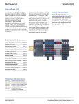
1
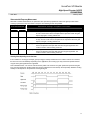
VersaPoint I/O Module
High-Speed Counter 24VDC Module
IC220MDD840
GFK-2052
February 2004
Module IC220MDD840 is a High-speed Counter module
that reads and processes fast pulse trains from 5VDC or
24VDC input sensors. Electronic sensors are
recommended. The module has four operating modes:
frequency measurement, event counting, time
measurement, and pulse generation.
Module MDD840 has a counter input, a control input, and
a configurable switching output that provides up to 500mA
of current. It can provide quick response times
independent of the control system.
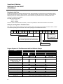
Module Specifications
Housing dimensions
(width x height x depth)
24.4mm x 120mm x 71.5mm
(0.96in. x 4.8in. x 2.86in.)
Connection style
5V sensors: 2-wire + shield
24V sensors: 2-wire and 3-wire
Actuators: 2-wire technology
Cable connections
Spring-clamp terminals
Conductor cross-section
0.2mm - 1.5mm (24-16 AWG)
Operating temperature
-25°C to +55°C,
(-13°F to +131°F)
Storage temperature
-25°C to +85°C
(-13°F to +185°F)
Operating humidity
75% average, 85% occasionally,
non-condensing. Take
appropriate measures against
increased humidity.
Storage humidity
75% average, 85% occasionally,
non-condensing.
Degree of protection
IP 20 according to IEC 60529,
DIN 40050
Class of protection
Class 3 according to VDE 0106,
IEC 60536, DIN 57106-1
2
2
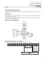
Module with I/O Terminal Strip
Module IC220MDD840 requires one (1) I/O Terminal Strip,
IC220TBK203 or two IC220TBK082, ordered separately.
See the ordering information below.
Features
Conditional event counting
Time measurement
Time- or state-driven frequency measuring
Pulse generating from 1kHz to 10kHz
Counting starts automatically
Selectable source and gate input combination
Supports RC filter on inputs
Support start and stop value changes on the fly
Power Consumption
24V Power Supply
19.2 to 30VDC including ripple
Communications
power UL
Current consumption
from local bus UL
Power consumption
from local bus UL
Segment supply
voltage US
Nominal current
consumption at US
7.5V
40mA typical,
50mA maximum
0.375W maximum
24VDC (nominal)
1A maximum
Ordering Information
IC220MDD840
High-speed Counter 1 In / 1 Out 24VDC
IC220TBK203
Terminal Strip Set Counter/Analog
required for 5V inputs
IC220TBK082
I/O Terminal Strip, unshielded, quantity
10, can be used for 24V inputs
1
VersaPoint I/O Module
High-Speed Counter 24VDC
IC220MDD840
GFK-2052
February 2004
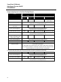
Installation Instructions
Terminal
Connections
5V sensors and actuator are connected
to the module via connector set
IC220TBK203. This connector set
provides a shield connector and a
standard connector. The shield
connector must be used for 5V signals.
Please refer to the detailed cable
connection instructions in your NIU User Manual.
For 24V signals, the cables do not need to be shielded
and two standard connectors IC220TBK082 can be
used instead of connector set IC220TBK203.
Connection Examples
24V Sensor, 2-Wire
Signal
Assignment
Connector A
1.1
S+
24V counter input (source)
2.1
G+
24V control input (gate)
1.2
UINI
+24V sensor voltage (source)
2.2
UINI
+24V sensor voltage (gate)
1.3
S-
Reference ground for the counter input
(source), sensor and segment voltage (
to GND)
2.3
G-
Reference ground for the control input
(gate), sensor and segment voltage (to
GND)
1.4, 2.4
Shield
Shield connection (high resistance and
capacitance to FE)
Connector B
24V Sensor, 3-Wire
1.1
S+ *
5V counter input (source)
2.1
G+ *
5V control input (gate)
1.2, 2.2
Out
Output, terminal points jumpered
internally
1.3, 2.3
GND
Reference ground for the output,
terminal points jumpered internally
1.4, 2.4
FE
Functional earth ground (to FE)
The short-circuit protected sensor voltage UINI is generated from the
segment voltage US. The main voltage UM is not used at the counter
terminal points.
The sensor signal is routed to
the S+ terminal. The sensor
receives power by the voltage
UINI.
The sensor signal is routed to
the S+ terminal. The sensor
receives power from UINI and
S- terminals.
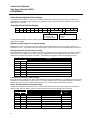
LED,
Color
Meaning
5V Sensor
Actuator
D
Green
Bus diagnostics
Shield
E
Red
For a 5V sensor, the sensor
signal is routed to the S+*
terminal. The S- terminal
forms the reference ground.
The sensor is grounded to FE
via the shield connector. The
5V supply for the sensor must
be provided externally.
2
Actuator power is provided
through output OUT1. The
load is switched directly by
the output. Do NOT exceed
the 500mA current rating of
the output. Excessive current
will cause the output to switch
off.
S
G
1
Yellow
On: Bus active
Flashing 0.5Hz (slow): Communications power present,
bus not active
Flashing 2Hz (med): Communications power present,
bus active, I/O error
Flashing 4Hz (fast): Communications power present,
module to the left of this module has failed. Modules to
the right are not configured
Off: Communications power not present, bus not active
Sensor supply short circuit
On: Connector 1 short-circuited between
terminals 1.2 and 1.3 or between 2.2 and 2.3
Off: No malfunction
Counter input status (source)
Control input status (gate)
Output status
On: Set, Off: Not set
VersaPoint I/O Module
High-Speed Counter 24VDC
IC220MDD840
GFK-2052
February 2004
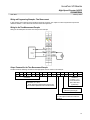
Internal Circuit Diagram
UL+
ULUANA
UINI
US
Communications power
Communications power
ground
I/O supply for analog
terminals
+24V sensor voltage from
main voltage
+24V segment voltage
Protocol chip (bus logic
including voltage
conditioning)
Microprocessor
Optocoupler
Digital input
Digital output
Transistor (output driver)
Coupling network
Module with multiplexer
filter and logic
Sensor supply with shortcircuit protection
Ground
Function earth ground
Terminal point
Voltage or data line
3
VersaPoint I/O Module
High-Speed Counter 24VDC
IC220MDD840
GFK-2052
February 2004
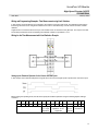
Typical Module Applications
Some typical applications for the High-speed Counter module are described below.
Event Counting
The example illustrated below shows an Event Counting application, in which sets of 100 screws are packed in a
cardboard box. The control input (2) enables the count at the counter input (3) when there are screws present in the
hopper. Each screw that falls out of the hopper into the box initiates a pulse at the counter input. When there are 100
screws in the box, the switching output (1) is set and the valve triggers the flap that closes the hopper. A new box can now
be filled.
Number
Sensor / Actuator
Associated Input / Output
1
Valve (flap control)
Switching output
2
Sensor (control signal)
Control input (gate)
3
Sensor (counting pulse)
Counter input (source)
Frequency Measurement
Frequency measurement can be used in applications that measure speeds.
Time Measurement
The module's time measurement feature can be used for many types of applications, such as:
Calculating the size of a part. On a conveyor belt, differences in size can be detected through differences in time.
Measuring speed to determine if the time falls outside a specified range. For example, the output can be set at a
specified maximum speed. Lower speeds can be measured in time measurement mode (which uses 16-bit values),
rather than in frequency measurement mode (which uses 24-bit measured values).
Pulse Generation
The module's pulse generation feature can be used to produce and output pulse trains with frequencies in the range of
1kHz to 10kHz modulo 500Hz.
4
VersaPoint I/O Module
High-Speed Counter 24VDC
IC220MDD840
GFK-2052
February 2004
Programming Data
ID code
BF hex (191 decimal)
Length code
02 hex
Input address area
4 bytes
Output address area
4 bytes
Parameter channel (PCP)
0 bytes
Register length (bus)
4 bytes
Data should always be consistent over 2 words (4 bytes) to assure accuracy.
Process Data
The High-speed Counter module is configured, controlled, and read using the process data it exchanges with the NIU.
Process data for the High-speed Counter module consists of:
Two words (four bytes) of output data that can be used to configure the module and to control the module's output.
Two words (four bytes) of input data that reflect the present states of the module's inputs.
The format of the process data is shown below and on the next page. Detailed descriptions of data formats are on the
following pages.
Process Data: the Output Words
The NIU sends the High-speed Counter two words of output data. This data can be used to configure and control the
module. The basic format of this data is:
5
VersaPoint I/O Module
High-Speed Counter 24VDC
IC220MDD840
GFK-2052
February 2004
Process Data: the Input Word
In return, the High-speed Counter sends the NIU two words of input data. The specific meaning of this data depends on
the present content of the output data received from the NIU.
Process Data Input Word, Basic Format
Unless the output words contain the Read Counter command, the input data word has the following content:
Bit 15 of Input Word 0 is set if:
The module is not yet configured
There is an invalid parameter in the default operating mode.
The counter is read without an operating mode having been present.
A reserved bit is set.
If Word 1 is not needed, its content is not evaluated.
Process Data Input Word, Read Counter Format
If the output words contain the Read Counter command, the input data word has the following content:
6
The command code (00000) is mirrored in bits 15 through 10 of Word 0.
The status of the control input (gate) is indicated in bit 9.
The status of the output (Out) or the result of evaluating of a relational condition is indicated in bit 8.
Bits 7 through 0 of Input Word 0 and Input Word 1 contain the results of the counting.
In time measurement mode, Input Word 1 contains the 16-bit value. Bits 0 through 7 of Input Word 0 are not used.
In frequency measurement mode or event counting mode, Input Word 1 and bits 7 through 0 of Input Word 0 contain
the 24-bit measurement or count value, where bit 7 of word 0 is the MSB.
VersaPoint I/O Module
High-Speed Counter 24VDC
IC220MDD840
GFK-2052
February 2004
Format of the High-speed Counter Module Commands (Process Data Outputs)
The NIU can send commands to the High-speed
Counter module to do the following:
to set the operating mode
to control the module's functions
to specify general conditions
to read the module's firmware version
to preset initial / final values
to stop or start the counter
to default the counter parameters
Command Sequence
Some of these commands must be sent in a
specific sequence:
1.
System settings (optional) are first. If no
system settings are required, this step can
be skipped.
2.
Operating Mode selection is next.
3.
Read Counter (optional). If the NIU does not
need to read the counter, this step can be
skipped.
The other output commands can be sent to the
High-speed Counter module at any time:
Read Firmware Version
Preset Initial Value and Preset Final Value
Stop Counter and Start Counter
Set Counter to Default
Action
Preset initial value
Assuring Data Consistency for the Output Commands
It is important to have data consistency of two output words to
prevent misinterpretation of the values. If the second output word is
related to the first, the High-speed Counter module must receive
them together. Otherwise, the second word will contain an old value
still present in the input word from an earlier transmission. If that
happens, the data will not be accepted properly.
To prevent this, the NIU can send Output Word 1 first with the default
value, and any command code other than that required. 000000bin
(Read Counter) is one possibility for this command code; it has no
effect on the parameterization of the module. If the module has not
been configured before a value is preset, or if no operating mode has
been commanded, bit 15 of Input Word 0 will indicate an error after
the transmission of this code. This error message can be ignored. It
has no effect on the preset value.
Next, transmit Output Word 0 with the command required for
presetting the value, without changing Output Word 1. The output
words are mirrored in the two input words. Input words 0 and 1 must
now contain the command code and the required preset. Bit 15 of
Input Word 0 must no longer indicate an error now. That shows that
the High-speed Counter module has adopted the value required.
Note that the High-speed Counter module will not accept a new value
if the NIU sends the same code for presetting the value several times
in succession. To change a preset value, at least one other
command code has to have been transmitted.
If it has become evident that data consistency is no longer ensured,
e.g., during transmission of the initial value, the command sequence
may appear as described by the table below.
Commands in Hexadecimal Format
Commands in Binary Format
Output Word 0
Output Word 1
Output Word 0
Output Word 1
4000
1111
0100 0000 0000 0000
0001 0001 0001 0001
Wait for
acknowledgement
Wait until Input Word 0 mirrors Output Word 0
Input Word 1 is NOT the same as Output Word 1
This acknowledgement shows that data consistency is not assured. The initial value must be retransmitted by sending
Output Word 1 followed by Output Word 0, as described above.
Enter initial value
(transmit Word 1)
0000
1111
0000 0000 0000 0000
0001 0001 0001 0001
Reenter initial value
(transmit Word 0)
4000
1111
0100 0000 0000 0000
0001 0001 0001 0001
Wait for
acknowledgement
Wait until Input Word 0 mirrors Output Word 0 and Input Word 1 mirrors Output Word 1.
7
VersaPoint I/O Module
High-Speed Counter 24VDC
IC220MDD840
GFK-2052
February 2004
Reference to the Output Commands
All of the commands and parameters that can be sent to the High-speed Counter module by the NIU are summarized
below for reference. They are explained in detail on the following pages.
Frequency Measurement
Output
Word 0
15
0
14
0
13
0
12
1
11
0
10
0
9
8
7
6
5
4
Parameter
3
2
1
0
15
0
14
0
13
0
12
1
11
0
10
1
9
0
8
0
7
R
6
5
Gate
3
D
2
1
Output
0
15
0
14
0
13
0
12
1
11
1
10
0
15
0
14
0
13
0
12
1
11
1
10
1
15
0
14
0
13
1
12
1
11
0
10
0
15
0
14
0
13
1
12
1
11
1
10
1
9
x
15
0
14
1
13
0
12
0
11
0
10
0
9
0
15
0
14
1
13
0
12
1
11
0
10
0
9
0
15
0
14
0
13
1
12
0
11
0
10
0
9
x
8
x
15
0
14
0
13
1
12
0
11
0
10
1
9
x
15
14
13
12
11
10
0
0
1
0
1
15
0
14
0
13
0
12
0
11
0
Event Counting
Output
Word 0
4
Time Measurement
Output
Word 0
9
0
8
0
7
6
Resolution
5
Out
4
Type
3
0
2
1
0
Relational Condition
Pulse Generation
Output
Word 0
9
0
8
0
7
0
6
0
5
0
4
3
2
Factor
1
0
System Settings
Output
Word 0
9
8
Input Type
7
6
5
4
Source – Gate Logic
3
Reset
2
1
0
Pulse Length
Read Firmware Version
Output
Word 0
8
x
7
x
6
x
5
x
4
x
8
7
0
Initial value
6
5
8
7
0
Final value
6
5
7
x
6
x
5
x
4
x
8
x
7
x
6
x
5
x
9
8
7
6
0
x
x
x
10
0
9
0
8
0
7
x
3
x
2
x
1
x
0
x
4
3
Initial value
2
1
0
4
3
Final value
2
1
0
3
x
2
x
1
x
0
x
4
x
3
x
2
x
1
x
0
x
5
4
3
2
1
0
x
x
x
x
x
x
x
6
x
5
x
4
x
3
x
2
x
1
x
0
x
Preset Initial Value
Output
Word 0
Word 1
Preset Final Value
Output
Word 0
Word 1
Stop Counter
Output
Word 0
Start Counter
Output
Word 0
Set Counter to Default
Output
Word 0
Read Counter
Output
Word 0
8
VersaPoint I/O Module
High-Speed Counter 24VDC
IC220MDD840
GFK-2052
February 2004
The System Settings Command
The System Settings command from the NIU to the High-speed Counter module is optional; it is not needed for all
operating modes. If needed, however, it must be sent as the first output command to the module, before sending the
command that specifies the operating mode. All System Settings except Pulse Length are accepted immediately in an
activated mode.
The System Settings command uses only Word 0 of the module output data.
15
14
13
12
11
10
0
0
1
1
0
0
9
8
Input Type
7
6
5
4
3
Source – Gate Logic
Operation
Reset
2
1
0
Pulse Length
Effects of the System Settings in Each Operating Mode
The parameters supplied by the System Settings command have different uses, depending on the operating mode.
Input Type
Source – Gate
Logic Operation
Reset
Frequency
Measurement
mode
00 = none
01 = switch filter
11 = enable source/gate operation
Event Counting
mode
00 = none
01 = switch filter
11 = enable source/gate operation
Time
Measurement
mode
00 = none
01 = switch filter
11 = enable source/gate operation
If source – gate
operation is
enabled in bits 9 –
8, then bits 7 – 4
set up relational
operations between
the source and
gate input signals
(for example, both
on or both off).
Pulse Generator
mode
00 = none
10 = setting for pulse generator
For all
modes, bit 3
determines
whether a
bus reset will
reset the
module’s
output, stop
counting, and
clear the
operating
mode setting.
Not used
Pulse Length
Not used
Sets length
of the output
pulse
Not used
Not used
System Settings: Input Type
The input type parameter can be used in all operating modes. This setting has three basically different functions. In all
operating modes, it can establish an input filter. In Pulse Generator mode, it sets up Pulse Generator operation. In all
modes except Pulse Generator mode, it can enable source – gate logic operations.
Bits 9 and 8
binary
Status Word
hex
Function
00
300x
Source and gate direct, each 100kHz filter
01
310x
Source and gate filter for mechanical contacts
10
320x
Enable Pulse Generator
11
33xx
Source – gate logic operation (not used in Pulse Generator mode).
Electronic switches are recommended for use with the High-speed Counter module. If mechanical switches such as relays
are used, source and gate filters should be set up to minimize the effects of the contacts bouncing. Filtering may not
eliminate the effect of mechanical contacts bouncing. When solid-state switches or light barriers are used, the filter must
be switched off. If different types of switches (mechanical and electronic) are used at the source and gate inputs, the
effects of wiring with and without filtering should be checked beforehand.
The High-speed Counter module always accepts the latest input configuration. For example, it is not possible to set a filter
for mechanical contacts first and then perform a source-gate logic operation. In that case, only the source-gate operation
would be accepted and the filter would no longer be active.
9
VersaPoint I/O Module
High-Speed Counter 24VDC
IC220MDD840
GFK-2052
February 2004
System Settings: Source – Gate Logic Operation
Source – gate logic operation can be used in all modes except Pulse Generator. In source – gate logic operation, a new
source signal is formed as a result of the logic operations performed on the digital source and gate input signals. The
original source signal is no longer available, The original gate signal can still be used. This function can perform most
common logic operations on the two module inputs, according to the setup made in bits 7 – 4 of the System Settings
command:
Bits 7 - 4
Status Word
hex
New Source Signal is Result of this Operation:
0001
331x
New source = Source NOR Gate
0011
333x
New source = Gate signal inverted
0101
335x
New source = Original source signal inverted
0110
336x
New source = Source EXOR Gate
0111
337x
New source = Source NAND Gate
1000
338x
New source = Source AND Gate
1100
33Cx
New source = Gate
1110
33Ex
New source = Source OR Gate
Results of Source – Gate Logic Operations on the Source and Gate Inputs
The following table compares the results of the Source – Gate operations for the possible combinations of the original
source input signal and the gate input signal. In the table, S' indicates the new source signal.
Gate
Source
OR
EXOR
AND
NOR
NAND
NOT S
G
NOT G
0
0
0
0
0
1
1
1
0
1
0
1
1
1
0
0
1
0
0
1
1
0
1
1
0
0
1
1
1
0
1
1
1
0
1
0
0
0
1
0
Other logic operations can be set up using different values in bits 7 – 4 of the Command word. The table below compares
the results of logic operations on the gate and source inputs that can be produced using different values in the Command
word.
Gate
Source
0000
0010
0100
1001
1010
1011
1101
1111
0
0
0
0
0
1
0
1
1
1
0
1
0
1
0
0
1
1
0
1
1
0
0
0
1
0
0
0
1
1
1
1
0
0
0
1
1
1
1
1
Defining a Function
To define a function for Source – Gate logic operations, create a table that shows all four possible combinations of the
gate and source inputs in the first two columns, then add the intended state of the new source’ input for each of these
combinations. For example, if source’ should always be 1 except when the original source input is 1 and the gate input is
0, the table looks like the one below. Program the command by setting the Command word bits to match, as shown (for
this example 1011 from bit 7 to 4):
10
Gate
Source
New Source’
Command Word Bits
0
0
1
1
0
1
0
1
1
1
0
1
4
5
6
7
VersaPoint I/O Module
High-Speed Counter 24VDC
IC220MDD840
GFK-2052
February 2004
System Settings: Reset
The Reset function can be used to control how the High-speed Counter module will react to a bus reset. By default, the
module resets its output, stops all counting operation, and clears the currently-selected operating mode. This can be
changed so that a bus reset will not affect the operation of the module, by using bit 3 of the output Command word:
Bit 3
Meaning
0
Bus reset resets the module output, stops counting, clears the
operating mode
1
Bus reset has no effect on module
System Settings: Pulse Length
The Pulse Length parameter can be used to change the length of the output pulse in event counting mode. The default
pulse length is 100ms. The Pulse Length parameter can be changed at any time. However, the change is not effective
until Event Counting mode is set.
Note: If the pulse length is set during event counting, after the value has been changed the command for setting
Event Counting mode must be resent.
The Pulse Length parameter is set using bits 0 to 2 of the Command word:
Bits 2, 1, 0
Pulse Length
Bits 2, 1, 0
Pulse Length
000
10ms
100
300ms
001
50ms
101
400ms
010
100ms
110
500ms
011
200ms
111
1000ms
11
VersaPoint I/O Module
High-Speed Counter 24VDC
IC220MDD840
GFK-2052
February 2004
Setting the Operating Mode to Frequency Measurement
The High-speed Counter module can measure frequencies up to 100kHz. To place the module in Frequency
Measurement mode, the NIU sends a command to the module using Output Word 0. Output Word 1 is not used.
Output Word Format for Frequency Measurement
15
14
13
12
11
10
0
0
0
1
0
0
9
8
7
6
5
4
3
2
1
0
Parameter
Bits 9 to 0 contain a time value or a gate state to start counting.
Parameter
Description
Decimal
Hexadecimal
Binary
Timecontrolled
Time gate after which a
count value is accepted
1 to 1000
1 to 3E8
00 0000 00001
to 11 1110 1000
Statecontrolled
Gate state with which a
count value is accepted
1020 to 1023
3FC to 3FF
11 1111 1100
to 11 1111 1111
When a time or state set is reached the counter is reset to the initial value.
Time-controlled Frequency Measurement
With time-controlled measurement, the parameter value (see above) specifies the gate time after which measurement is
performed, as a multiple of 10ms. As the count gate time increases, the count frequency decreases.
Count gate time
Count resolution
= 1 / Count time = 1 / (parameter value x 10ms)
Frequency
= Count value x 100 / Parameter value
= Parameter value X 10ms
The gate time should be selected to match the needs of the application. Longer gate times provide greater resolution and
accuracy. Shorter gate times provide rapid response but decreased resolution. If the application requires simple count
value processing, a resolution of 1Hz avoids the need for converting the count value into a frequency.
Time-Controlled Frequency Examples
The following table shows some typical count times and frequencies. For example, if the count time parameter is 10
(decimal), then the count time is 0.1 second and the count frequency is 10Hz. If the count time parameter is 1000, then
the count time is 10 seconds and the count frequency is 0.1Hz.
Count Time Parameter
12
Time in Seconds
Resolution in Hz /
LSB
(decimal)
(hex)
1
1001
0.01
100
2
1002
0.02
50
10
100A
0.1
10
50
1032
0.5
2
100
1064
1
1
500
11F4
5
0.2
1000
13EA
10
0.1
VersaPoint I/O Module
High-Speed Counter 24VDC
IC220MDD840
GFK-2052
February 2004
State-controlled Frequency Measurement
With state-controlled measurement, the parameter value (see above) specifies the state of the gate input after which
counting is performed or the count value is accepted. The following choices are possible:
Count Gate Parameter
Gate State for Counting or Acceptance of Count Value
(decimal)
(hex)
1020
13FC
High level
Counting occurs while the gate input is High. Counting stops when it changes
to Low. The last count value is accepted into the input data. When the gate
input is High again, counting restarts at 0.
1021
13FD
Low level
Counting occurs while the gate input is Low. Counting stops when it changes
to High. The last count value is accepted into the input data. When the gate
input is Low again, counting restarts at 0.
1022
13FE
Rising edge
Counting starts immediately after the command is received. The current count
value is accepted into the input data each time the gate signal rises. The
counter is reset to 0 and counting continues.
1023
13FF
Falling edge
Counting starts immediately after the command is received. The current count
value is accepted into the input data each time the gate signal falls. The
counter is reset to 0 and counting continues.
Counting Phase Depending on the Gate State
If the condition for counting (for example, gate input High) is already satisfied when the module receives the command,
the first count occurs immediately. Depending on the application, this counting cycle may need to be rejected because
only part of the gate signal has been registered.
This is illustrated below. The "source" train shows the pulses to be counted. The "gate" pulse train represents the gate
input. Counting starts when the NIU sends the Frequency Measurement command (in the output data). Whether counting
actually occurs depends on the parameter and the gate signal.
13
VersaPoint I/O Module
High-Speed Counter 24VDC
IC220MDD840
GFK-2052
February 2004
Setting the Operating Mode to Event Counting
If the module should count the occurrences of a specific event, send the module an Event Counting command using
Output Word 0. Parameters in Word 0 specify the conditions for event counting. Bits 9 and 8 of Word 0 must be set to 0.
Output Word 1 is not used.
Output Word Format for Event Counting
15
0
14
0
13
0
12
1
11
0
10
1
9
0
8
0
7
R
6
5
Gate
Repetitions
0 = single count
1 = constant repeat
4
3
D
2
1
Output
0
Count Direction:
0 = down
1 = up
Counting starts immediately after the module receives the command. In Event Counting mode, the operating range for all
options is up to 100kHz.
Repetitions: Specify single count or repeated counting
If Repetitions is set to 0, counting stops when the final value is reached and the count value remains at that value. If
Repetitions is set to 1, the counter is reset when the final value is reached and the count is repeated from the initial value.
Gate: Specify how the Gate input affects counting
The Gate parameter specifies how the state of the Gate input signal affects the counting process. The choices are listed
below. When the gate signal is used to start counting, a response time of 200 microseconds must be allowed. Count
pulses that occur within this period do not register. This response time applies to starting and stopping the count.
Bit 6 / 5 / 4
bin
dec
000
0
001
1
010
2
011
3
110
4
101
5
110
6
111
7
Meaning
No function
Count at High level
Count at Low level
Start counting on rising edge of Gate input
Start counting on falling edge of Gate input
Reserved
Reserved
Count at High level, reset the count value on a rising edge
Count Direction: Select up or down counting
Bit 3 determines the count direction. Note that the default count direction is DOWN (bit 3 = 0). Starting event counting with
a parameter of 1400H produces a down counter. If no initial or final value is set, counting starts and ends at 0. The final
value is reached if an up counter counts from FFFFFFH to 0 or a down counter counts from 0 to FFFFFFH.
Output: Set up the operation of the module output
This parameter determines the operation of the module's output when the final count value is reached. The standard
length of a high and a low pulse is 100ms. It can be changed using the System Settings output command.
Bit 2 / 1 / 0
bin
dec
000
0
001
1
010
2
011
3
110
4
101
5
110
6
111
7
14
Meaning
No function
High pulse
Low pulse
Toggle L
Toggle H
High
Low
Reserved
Output not active
Positive pulse generated
Negative pulse generated
Previous state inverted
Previous state inverted
Output high
Output low
Reserved
Initial Output
State
low
low
high
low
high
low
high
-
VersaPoint I/O Module
High-Speed Counter 24VDC
IC220MDD840
GFK-2052
February 2004
Setting the Operating Mode to Time Measurement
If the module should count the occurrences of a specific event, the NIU sends a command in the output data to place the
module in Time Measurement mode using Output Word 0. Additional parameters in Word 0 specify the conditions for time
measurement. Bits 9, 8, and 3 of Word 0 must be set to 0.Output Word 1 is not used.
The count value in time measurement mode occupies 16 bits. Measurement starts on a rising edge. Measurement of
pulse length ends on a falling edge. Measurement of period starts on the next rising edge. Only when measurement is
complete is the count value accepted into the process data. If no counting edge is detected within the timeout, the count
value is cleared. An error message is generated if a timeout occurs.
Output Word Format for Time Measurement
15
14
13
12
11
10
9
8
0
0
0
1
1
0
0
0
7
6
Resolution
5
4
3
Out
Type
0
Output:
0 = Output not used
1 = Set output if relation condition satisfied
2
1
0
Relational Condition
Type:
0 = Measure period
1 = Measure pulse length
Resolution: Specify the increments for all parameters
Resolution determines the value of the least significant bit, as shown below. The indicated resolution is valid for all values,
including preset conditions such as an initial or final value. For example, if the resolution is 2ms, the initial value would be
entered as a multiple of 2ms. So an entry of 25, multiplied by the 2ms resolution, would give an initial value of 50ms.
Bit 7 / 6
00
Meaning
2 microseconds
01
10
11
2 milliseconds
10 milliseconds
reserved
Range
(without relational condition): 250µs to 131ms
(with relational condition): 1ms to 131 ms
2ms to 131 seconds (2 minutes, 11 seconds)
10 ms to 655 seconds (10 minutes, 55 seconds)
-
Timeout After
150ms
131 seconds
655 seconds
-
Out: Specify whether the output will be set
The Output parameter determines whether the output will be set if a specific relational condition is satisfied (Bit 5 = 1) or
not (Bit 5 = 0).
Type: Specify pulse period or pulse length measurement period
The Type parameter determines whether the measurement period will be of pulse period (see "a" below; Bit 4 = 0), or
pulse length (see "b" below; Bit 4 = 1).
15
VersaPoint I/O Module
High-Speed Counter 24VDC
IC220MDD840
GFK-2052
February 2004
Relational Condition: Set up the logical operation that will control the output
The Relational Condition parameter specifies a condition for the output behavior during time measurement. Compliance
with the limit values specified in the relation condition is indicated through the output of bit 8 (Out). Only the initial and/or
the final value from the event counting can be use as limit values. Because the count value only occupies 16 bits, only the
lower 16 bits of the initial value and the final value are taken into account.
Relational Conditions Parameter
Bit 2 / 1 / 0
bin
dec
000
0
001
1
010
2
011
3
110
4
101
5
110
6
111
7
Meaning
No relational condition
Count value greater than or equal to initial value
Count value less than initial value
Count value within initial and final values
Count value outside initial and final values
Count value greater than final value with hysteresis
Count value less than initial value with hysterisis
reserved
Whether or not a limit value is included in the condition depends on the condition. Internally, the module reduces each
condition to a comparison of count value less than initial value and/or count value greater than final value.
The illustration below shows the operation of the output with different selections for relational conditions. In the illustration:
16
X = initial value
Y = final value
● = limit value included
o = limit value not included
VersaPoint I/O Module
High-Speed Counter 24VDC
IC220MDD840
GFK-2052
February 2004
Effect of Relational Condition If the Output is Used
If the output is being used (output bit 5 is set to 1), then bit 8 in Input Word 0 reflects the state of the output. If the
relational condition is satisfied. the output is set and bit 8 in Input Word 0 shows a 1, reflecting the output state. If the
relational condition is not satisfied, the output is reset and a 0 is shown in bit 8 of Input Word 0.
Example of Relational Condition
The following illustration shows the effect of a relational condition:
If the count value is less than the initial value, the relational condition is satisfied and OUT is set to 1.
If the count value is greater than or equal to the initial value, and less than or equal to the final value, the relational
condition is not satisfied and OUT is set to 0.
If the count value is greater than the final value, the condition is satisfied and OUT is set to 1.
Effect of Relational Condition If the Output is Not Used
If the output is not being used (output bit 5 is set to 0), then once the relational condition is satisfied, the bit for the output
is set in the input data word (bit 8 of Word 0 = 1). Input bit 8 remains at 1 unless it is specifically reset. Bit 8 of Output
Word 0 is set to 1 until bit 8 in the input data Word 0 changes to 1. If the relational condition is not satisfied, a 0 appears in
the input data word (bit 8 of Word 0 = 0).
Effect of Hysterisis
The bottom two diagrams on the previous page show the effect of hysteresis. In the diagrams, the dashed line illustrates
the output state as a function of the previous state of the OUT output bit and the measured value. If, for example, in the
diagram below, the measurement is between the initial and final values, OUT can be either 0 or 1. If OUT was 0, it
remains at 0. If OUT was 1, it remains at 1. Hysteresis can be used to stabilize the output behavior of measured values
that fluctuate around certain limit values.
Example 2
This illustration again shows the behavior of an output with hysteresis:
If the time measured has not yet been greater than or equal to the final value, the condition is satisfied and OUT is 1.
If the time measured is greater than or equal to the final value, the condition is no linger satisfied and OUT is 0.
If the time measured becomes smaller, but still remains greater than or equal to the initial value, OUT remains 0.
If the time measured is less than the initial value, OUT becomes 1.
OUT only returns to 0 again if the measured value becomes greater than or equal to the final value.
17
VersaPoint I/O Module
High-Speed Counter 24VDC
IC220MDD840
GFK-2052
February 2004
Setting the Operating Mode to Pulse Generator
In Pulse Generator mode, the High-speed Counter module can produce frequencies from 1kHz through 10kHz.
Frequencies can be selected in 500Hz increments as part of the module configuration.
The NIU sends a command in the output data to place the module in Pulse Generator mode using Output Word 0. Output
Word 1 is not used.
Output Word Format for Pulse Generation
15
14
13
12
11
10
9
8
7
6
5
0
0
0
1
1
1
0
0
0
0
0
4
3
2
1
0
Factor
Setting Up the pulse frequency
To set up the pulse frequency, the output word must specify the number of 500Hz increments in the intended frequency.
For example, for 1000Hz, there would be two 500Hz increments, so the output word would contain the value ("factor") 2.
The table below shows the pulse frequencies for each possible factor value that can be specified in the output word.
Dec
Hex
0
1
2
3
4
5
6
7
8
9
00
01
02
03
04
05
06
07
08
09
Nominal
Frequency
1000
1500
2000
2500
3000
3500
4000
4500
5000
5500
Actual
Frequency
1000
1497
2000
2500
3012
3521
4000
4505
5000
5495
Error
in %
0
-0.2
0
0
0.4
0.6
0
0.11
0
-0.09
Dec
Hex
10
11
12
13
14
15
16
17
18
0A
0B
0C
0D
0E
0F
10
11
12
Nominal
Frequency
6000
6500
7000
7500
8000
8500
9000
9500
10000
Actual
Frequency
5988
6494
6993
7519
8000
8475
9009
9525
10000
Error
in %
-0.2
-0.09
-0.1
0.25
0
-0.29
0.1
0.26
0
System Settings for Pulse Generation
In addition to setting up the pulse frequency as explained above, Pulse Generator mode must also be selected using the
System Settings command ("Input Type" = 10, Pulse Generator mode) as described previously.
18
VersaPoint I/O Module
High-Speed Counter 24VDC
IC220MDD840
GFK-2052
February 2004
Reading the Counter
The application can read the present value of the counter using the optional Read Counter command. If this command is
used, it must be sent after the Operating Mode commands. The Read Counter command can be used in all operating
modes.
The NIU sends the Read Counter command to the module using Output Word 0, bits 15 - 8. Bits 7 through 0 are not
relevant. Output Word 1 is not used.
Output Word Format for Read Counter
15
14
13
12
11
10
9
8
7
6
5
4
3
2
1
0
0
0
0
0
0
0
0
0
x
x
x
x
x
x
x
x
Content of the Input Words
After the module receives a Read Counter command, it sends the information in the input data words as shown below .
The input data format for Time Measurement is different than for Event Counting / Frequency Measurement modes.
Input Data for Time Measurement mode
Bit 15 (E) = Error bit, 0 = no error
Bits 14 - 10 = Mirror of the command bits, i.e. all 0
Bit 9 (G) = Status of the Gate input signal
Bit 8 (S) = Status of the output or result of the evaluation of the relational condition without using the output
Bits 0 - 7 of Word 0 (x) = don't care
Word 1 = 16-bit measured value
Input Word 0
Input Word 1
high byte
low byte
15 14 13 12 11 10 9
E
0
0
0
0
0
high byte
low byte
8
7
6
5
4
3
2
1
0 15 14 13 12 11 10 9
G S
x
x
x
x
x
x
x
x
8
7
6
5
4
3
2
1
0
Time Measurement mode: 16-bit measured value
Input Data for Event Counting or Frequency Measurement mode
Bit 15 (E) = Error bit, 0 = no error
Bits 14 - 10 = Mirror of the command bits, i.e. all 0
Bit 9 (G) = Status of the Gate input signal
Bit 8 (x) = not used
Bits 0 - 7 of Word 0 = most significant bits of the 24-bit count value
Word 1 = less significant bits of the count value. The count value must be masked out of the two input words:
count = ( IN (0) & 00FFH ) x 65536 + IN (1)
Input Word 0
Input Word 1
high byte
low byte
15 14 13 12 11 10 9
8
E
x
0
0
0
0
0
G
7
6
5
4
3
high byte
2
1
0 15 14 13 12 11 10 9
low byte
8
7
6
5
4
3
2
1
0
Event Counting or Frequency Measurement mode: 24-bit measured value
19
VersaPoint I/O Module
High-Speed Counter 24VDC
IC220MDD840
GFK-2052
February 2004
Reading the Firmware Version
The application can read firmware version of the High-speed Counter using the Read Firmware Version command. This
command can be used at any time. Only Output Word 0 is used for this command. The command is mirrored immediately
in Input Word 0. Input Word 1 contains the firmware version.
Output Word Format for Read Firmware Version
15
14
13
12
11
10
9
8
7
6
5
4
3
2
1
0
0
0
1
1
1
1
x
x
x
x
x
x
x
x
x
x
Input Words Returned Following a Read Firmware Version Command
In response to the Read Firmware Version command, the High-speed Counter module sends back the two input data
words. Input Word 0 mirrors the command. Input Word 1 contains the firmware version in the format A.BC.
Input Word 0
15
14
13
12
11
10
9
8
7
6
5
4
3
2
1
0
0
0
1
1
1
1
x
x
x
x
x
x
x
x
x
x
13
12
11
10
9
8
7
6
5
4
3
2
1
0
Input Word 1
15
14
A
B
C
x
In the example response below, Input Word 1 contains the value 1360H. This corresponds to firmware version 1.36.
Input Word 1
15
14
0
0
1
20
13
12
11
10
0
1
0
0
3
9
8
7
6
1
1
0
1
6
5
4
3
2
1
0
0
0
0
1
0
0
0
VersaPoint I/O Module
High-Speed Counter 24VDC
IC220MDD840
GFK-2052
February 2004
Presetting an Initial Value or Final Value
The application can specify initial and final values for Event Counting or Time Measurement mode using the Preset
commands. For Event Counting, the initial and final values can be 24-bit values. For Time Measurement, the initial and
final values must be 16-bit values.
The Preset commands can be sent at any time. They are accepted immediately, even during counting or time
measurement.
If a new initial value is set while counting, the counter is set to this value immediately, regardless of its current state.
If a new final value is set while counting, the value is accepted immediately for the current count.
Repeat Counting if No Initial value has been Set
If no initial value has been set for repeat counting, the counter starts at 0 (not 1). It counts the number of times specified
by the final value, then resets to 0 on the next pulse. For example, if there is no initial value and the final value is 10, the
counter increments from 0 to 9 (10 counts), then resets to 0.
Output Word Format for Preset Initial Value Command
Output Word 0
15
14
13
12
11
10
9
8
0
1
0
0
0
0
0
0
13
12
11
10
9
8
7
6
5
4
3
2
1
0
Initial value
Output Word 1
15
14
7
6
5
4
3
2
1
0
6
5
4
3
2
1
0
2
1
0
Initial value
Output Word Format for Preset Final Value Command
Output Word 0
15
14
13
12
11
10
9
8
0
1
0
1
0
0
0
0
13
12
11
10
9
8
7
Final value
Output Word 1
15
14
7
6
5
4
3
Final value
Resolution of the Preset Values
When entering initial and final values for Time Measurement mode, any resolution that has been set by the mode
command also applies to these initial and final values. For example, it the resolution will be 2ms and the initial value will
be 50ms, then the initial value must be entered as 25 decimal (19H).
21
VersaPoint I/O Module
High-Speed Counter 24VDC
IC220MDD840
GFK-2052
February 2004
Start and Stopping the Counter in Event Counting Mode
Event counting starts as soon as the High-speed Counter receives the Event Counting mode command. It is not
necessary to send a Start Counter command to initiate counting.
If the count should start at a defined initial state, first send the Set Counter to Default command to clear the counter. See
below.
The NIU sends the Stop Counter command (2000H) to stop counting, and the Start Counter command (2400H) to restart
counting.
The count value is frozen by the Stop Counter command. It resumes again at the frozen value when the Start Counter
command is received.
The Start Counter and Stop Counter commands use Output Word 0. Output Word 1 is not used.
Output Word Format for Stop Counter Command
15
14
13
12
11
10
9
8
7
6
5
4
3
2
1
0
0
0
1
0
0
0
x
x
x
x
x
x
x
x
x
x
Output Word Format for Start Counter Command
15
14
13
12
11
10
9
8
7
6
5
4
3
2
1
0
0
0
1
0
0
1
x
x
x
x
x
x
x
x
x
x
Defaulting the Counter
The Set Counter to Default command is valid in all operating modes.
Event counting starts as soon as the High-speed Counter receives the Event Counting mode command. If the counter
should start at a predefined default condition, the NIU must send the Set Counter to Default command (2800H).
The Set Counter to Default command does the following:
it sets the Pulse Length to the default value
it sets the input configuration to 100kHz
it stops the counter
it clears the operating mode
The Set Counter to Default command does NOT change the configured Reset behavior.
If the system is being tested, use this command to default the counter before switching to a new operating mode.
The Set Counter to Default command uses Output Word 0. Output Word 1 is not used.
Output Word Format for Set Counter to Default Command
22
15
14
13
12
11
10
9
8
7
6
5
4
3
2
1
0
0
0
1
0
1
0
x
x
x
x
x
x
x
x
x
x
VersaPoint I/O Module
High-Speed Counter 24VDC
IC220MDD840
GFK-2052
February 2004
Wiring and Programming Examples
The examples in this section show typical device wiring and programming sequences for event counting and for time
measurement.
Event Counting
In this example, the module is used for counting up. A light barrier is connected to the source input as shown below. This
barrier provides the counting pulses.
Counting starts at 123H. The module's output turns on an indicator light when counting starts. The output needs to be
inverted each time the count reaches 132H.
Wiring for the Event Counting Example
Output Command for the Event Counting Example
The NIU sends the following command to the High-speed Counter module in this example:
15
14
13
12
11
10
9
8
7
6
5
4
3
2
1
0
0
0
0
1
0
1
0
0
1
0
0
0
1
1
0
0
Command
Gate – Source
Logic not used
1 = constant repeat
100 = invert
previous output
state when final
value is reached,
set high at initial
state
Count Direction: 1 = up
23
VersaPoint I/O Module
High-Speed Counter 24VDC
IC220MDD840
GFK-2052
February 2004
Programming Sequence for the Event Counting Example
Action
Set counter to default
Commands in Hexadecimal
Format
Output
Word 0
Output
Word 1
Output Word 0
Output Word 1
2800
xxxx
(don't care)
0010 1000 0000 0000
xxxx xxxx xxxx xxxx
(don't care)
Wait for acknowledgement
Preset initial value to 123H
(see below)
Wait until Input Word 0 mirrors Output Word 0
(Input Word 1 is not relevant at this point)
4000
Wait for acknowledgement
Preset final value to 132H
5000
0100 0000 0000 0000
0000 0001 0010 0011
0132
0101 0000 0000 0000
0000 0001 0011 0010
Wait until Input Word 0 mirrors Output Word 0
and Input Word 1 mirrors Output Word 1
148C
Wait for acknowledgement
Read counter
0123
Wait until Input Word 0 mirrors Output Word 0
and Input Word 1 mirrors Output Word 1
Wait for acknowledgement
Set operating mode = event
counting, up counting, output
active, output = toggle
Commands in Binary Format
xxxx
0001 0100 1000 1100
xxxx xxxx xxxx xxxx
Wait until Input Word 0 mirrors Output Word 0
0000
xxxx
0000 0000 0000 0000
xxxx xxxx xxxx xxxx
Wait for acknowledgement
Wait until (Input Word 0 & FC00H) mirrors (Output Word 0 & FC00H)
Read count value
Count value = Input Word 1
In this example, the counting range is from 123H to 132H, so the count value
only occupies Input Word 1. If the value occupies more than 16 bits, the value
must be masked out of the two input words, as described.
If the preset initial value and/or final value are 24-bit values, the preset commands have this format:
Preset initial value 123456H
4012
Wait for acknowledgement
Preset final value 789ABCH
Wait for acknowledgement
24
3456
0100 0000 0001 0010
0011 0100 0101 0110
Wait until Input Word 0 mirrors Output Word 0
and Input Word 1 mirrors Output Word 1
5078
9ABC
0101 0000 0111 1000
1001 1010 1011 1100
Wait until Input Word 0 mirrors Output Word 0
and Input Word 1 mirrors Output Word 1
VersaPoint I/O Module
High-Speed Counter 24VDC
IC220MDD840
GFK-2052
February 2004
Wiring and Programming Examples: Time Measurement
In this example, the module is used to measure the length of pulses. The output is to follow a hysteresis loop with the
relational condition: "count value less than initial value with hysteresis".
Wiring for the Time Measurement Example
Wiring for this example is the same as for the previous example:
Output Command for the Time Measurement Example
The NIU sends the following command to the High-speed Counter module in this example:
15
14
13
12
11
10
9
8
7
6
5
4
3
2
1
0
0
0
0
1
1
0
0
0
0
1
1
1
0
1
1
0
Command
Resolution: 01 = 2ms
When specifying initial and final values note
the resolution specified for time measurement.
Relational
Condition: 110 =
Count value less
than initial value
(hysteresis)
Type:
1 = Measure pulse length
Out:
1 = Set output if relational condition is
satisfied
25
VersaPoint I/O Module
High-Speed Counter 24VDC
IC220MDD840
GFK-2052
February 2004
Program Sequence for the Time Measurement Example
Action
Set counter to default
Commands in Hexadecimal
Format
Output
Word 0
Output
Word 1
Output Word 0
Output Word 1
2800
xxxx
(don't care)
0010 1000 0000 0000
xxxx xxxx xxxx xxxx
(don't care)
Wait for acknowledgement
Preset initial value to 14H
(see below)
Wait until Input Word 0 mirrors Output Word 0
4000
Wait for acknowledgement
Preset final value to 28H
0014
0100 0000 0000 0000
0000 0000 0001 0100
Wait until Input Word 0 mirrors Output Word 0
and Input Word 1 mirrors Output Word 1
5000
Wait for acknowledgement
Set operating mode = time
measurement, with
parameters as described
Commands in Binary Format
0028
0101 0000 0000 0000
0000 0000 0010 1000
Wait until Input Word 0 mirrors Output Word 0
and Input Word 1 mirrors Output Word 1
1876
Wait for acknowledgement
xxxx
0001 1000 0111 0110
xxxx xxxx xxxx xxxx
Wait until Input Word 0 mirrors Output Word 0
The following steps are not needed if only the output behavior is important for the application:
Read counter
0000
xxxx
0000 0000 0000 0000
xxxx xxxx xxxx xxxx
Wait for acknowledgement
Wait until (Input Word 0 & FC00H) mirrors (Output Word 0 & FC00H)
16-bit count value
Count value = Input Word 1
Time in ms
Time = count value x resolution: resolution = 2ms
When the mode command is sent, the High-speed Counter module immediately starts counting (time measurement) the
signals at the input. The pulse length starts at 0ms, and slowly increases (see A below). As long as the pulse length is
less than the final value (80ms), the output remains at 1. When the pulse length equals the final value (B in the diagram)
the output is set to 0. The pulse length continues to increase (C below) until it reaches 120ms. It then decreases again
(segment D). If the pulse length is equal to the initial value (40ms, point E below) the output is set to 1. If the pulse length
shortens further, the output remains at 1.
26
VersaPoint I/O Module
High-Speed Counter 24VDC
IC220MDD840
GFK-2052
February 2004
Wiring and Programming Examples: Time Measurement using Limit Switches
In this example, two limit switches are connected to the module's source and gate inputs. The application measures the
time during which the source and gate limit switches are both at 1 simultaneously. If a limit value is exceeded, it will be
detected.
A light barrier is connected to the source input, and another sensor is connected to the gate input. The output is not used.
The module provides the results of evaluating the relational condition in Input Word 1, bit 9.
Wiring for the Time Measurement with Limit Switches Example
Setting up the Relational Operation for the Source and Gate Inputs
In this example, the module should perform a logical OR on the source and gate inputs to produce the new source' input:
Before setting the operating mode, the NIU must specify this relational operation using the following System Settings
command:
15
14
0
0
13
12
11
10
1
1
0
0
Command
9
8
1
1
Input Type
11 = Logic
Operation
7
6
5
4
1
1
1
0
Source – Gate Logic
Operation: 1110 =
Logical OR
3
0
Reset
0 = no
response
2
1
0
0
0
0
Pulse Length:
not relevant
27
VersaPoint I/O Module
High-Speed Counter 24VDC
IC220MDD840
GFK-2052
February 2004
Presetting the Initial Value
The NIU next presets the initial value with the limit value. During operation, the Out bit in the Input word will be used to
indicate when the limit value has been exceeded. In this example, the limit is 30 seconds. Therefore, an initial value of
3000ms is preset. The resolution will be 2ms. The value entered in the parameter word for the Default Initial Value
command is 15000 decimal (3A98H).
The initial value is preset using:
Word 0 = 4000H
Word 1 = 3A98H
These two words should have data consistency. If that is not possible, the NIU should send Word 1 then Word 0.
Setting the Operating Mode to Time Measurement
After setting up the relational operation (and other system settings) and entering the presets as described above, the NIU
can send the Operating Mode command to the module, placing it in Time Measurement mode.
15
14
13
12
11
10
9
8
7
6
5
4
3
2
1
0
0
0
0
1
1
0
0
0
0
1
0
1
0
0
0
1
Command
Relational
Condition: 001 =
Count value equal
to initial value
Resolution: 01 = 2ms
When specifying initial and final values note
the resolution specified for time measurement.
Type: 1 = Measure pulse length
Out: 0 = not used
Program Sequence for Time Measurement with Limit Switches Example
Action
Set counter to default
Wait for acknowledgement
System Settings: logic
operation on source - gate
active command
Wait for acknowledgement
Preset initial value to 3A98
Wait for acknowledgement
Time measurement mode,
pulse length measurement
Wait for acknowledgement
Read counter
Wait for acknowledgement
16-bit count value
Time in ms
28
Commands in Hexadecimal
Commands in Binary Format
Format
Output
Output
Output Word 0
Output Word 1
Word 0
Word 1
2800
xxxx
0010 1000 0000 0000
xxxx xxxx xxxx xxxx
(don't care)
(don't care)
Wait until Input Word 0 mirrors Output Word 0
33E0
xxxx
0011 0011 1110 0000
xxxx xxxx xxxx xxxx
4000
1851
Wait until Input Word 0 mirrors Output Word 0
3A98
0100 0000 0000 0000
0011 1010 1001 1000
Wait until Input Word 0 mirrors Output Word 0
and Input Word 1 mirrors Output Word 1
xxxx
0001 1000 0101 0001
xxxx xxxx xxxx xxxx
Wait until Input Word 0 mirrors Output Word 0
0000
xxxx
0000 0000 0000 0000
xxxx xxxx xxxx xxxx
Wait until (Input Word 0 & FC00H) mirrors (Output Word 0 & FC00H)
Count value = Input Word 1
Time = count value x resolution: resolution = 2ms
VersaPoint I/O Module
High-Speed Counter 24VDC
IC220MDD840
GFK-2052
February 2004
Technical Data
Safety Devices
Short-circuit protection
for the sensor power supply: Electronic (automatic restart)
for the switching output: short-circuit protected (automatic restart)
Electrical Isolation
To provide electrical isolation between the logic level and the I/O it is necessary to supply the I/O Station NIU and
the High-speed Counter module using the NIU or a power terminal from separate power supplies. The different
24V supplies must not be connected.
Common potentials
24V main voltage (UM) and 24V segment voltage (US) have the same potential (GND). Functional earth ground
(FE) is a separate potential area.
Separate system potentials consisting of NIU/power terminal and I/O terminal
- Test distance
- Test Voltage
5V supply of incoming remote bus / 7.5V supply (bus logic)
500VAC, 50Hz, 1 min.
5V supply of outgoing remote bus / 7.5V supply (bus logic)
500VAC, 50Hz, 1 min.
7.5V supply (bus logic) / 24V supply ( I/O)
500VAC, 50Hz, 1 min.
24V supply (I/O) / functional earth ground
500VAC, 50Hz, 1 min.
Noise Immunity
Surge voltage
(Different than other VersaPoint I/O
modules)
EN61000-4-5 / IEC 61000-4-5
Criterion B
Signal lines
0.5kV (asymmetrical)
Error Messages to the Higher-Level Control or Computer System
Short circuit / overload of sensor
supply
If the sensor supply is short-circuited, the red "Error" LED lights. After a
delay of about 1.4 second, the module generates an I/O error message.
Also, the diagnostic D LED on the module flashes at medium (24Hz)
frequency.
29
VersaPoint I/O Module
High-Speed Counter 24VDC
IC220MDD840
GFK-2052
February 2004
Discrete Inputs
Number
1 counter input for 24V signals, or
1 counter input for 5V signals
1 control (gate) input for 24V signals, or
1 control (gate) input for 5V signals
Input resistance
24V inputs: approximately 5.7 k Ohms
5V inputs: approximately 1.7 k Ohms
Switching thresholds
24V range:
5V range:
maximum low level voltage:
minimum high level voltage:
2.5V + 1V
Maximum input voltage
24V inputs:
5V input:
30V
8V
Common potentials
main supply, ground
Nominal input voltage
24VDC
Permissible range
-0.5V < UIN < 30VDC
Nominal inputp current
5mA
Delay time
less than 5 microseconds
Input signals
Input signals at the source and gate must be digital
Switches
Electronic switching preferred. Mechanical contacts can be used in certain
applications, through the use of input filtering to compensate for contact
bounce.
Input Characteristic Curve
Input voltage (V)
Typical input current (mA)
-0.5V < IIN < 0
0
3
0.6
6
1.1
9
1.7
12
2.3
15
2.4
18
3.6
21
4.3
24
5.0
27
5.5
30
6.1
Concurrent Channel Derating
None
30
less than 5V
more than 15V
VersaPoint I/O Module
High-Speed Counter 24VDC
IC220MDD840
GFK-2052
February 2004
Switching Output
Number
1
Nominal output voltage
24VDC
Nominal current
0.5A maximum
Differential voltage for nominal current
less than 1V
Protection
Short circuit, overload
Nominal load:
Ohmic
Lamp
Inductive
>48Ω / <12W
<12W
<12VA (>48Ω, <1.2H)
Signal delay ON
Ohmic nominal load
Lamp nominal load
Inductive nominal load
<50 microsecond typical
<25 microsecond typical
<1ms typical
Signal delay OFF:
Ohmic nominal load
Lamp nominal load
Inductive nominal load
Result of ohmic or lamp overload
<1ms typical
<1ms typical
<30ms typical
Auto-restart after eliminating the overload
Note: a bulb characteristic can delay the auto-restart after
the overload has been eliminated. This delay can be
reduced by briefly switching the output.
Result of inductive overload
Can destroy output
Result of short circuit
Auto-restart after correcting the condition
Limitation of the demagnetization voltage induced
on current interruption
Approximately -18V
Overcurrent disconnection
Minimum at 0.7A
Reverse voltage endurance against short pulses
Yes
Maximum revese current
0.5A
Strength against permanently applied surge
voltage
No
Output Characteristic when Switched On (typical)
Output Current (A)
Differential output voltage (V)
0
0
0.1
0.25
0.2
0.35
0.3
0.45
0.4
0.55
0.5
0.65
Concurrent Channel Derating
None
31
VersaPoint I/O Module
High-Speed Counter 24VDC
IC220MDD840
GFK-2052
February 2004
Sensor Supply
Nominal output voltage
24VDC
Nominal current
0.5A maximum
Differential voltage for nominal
current
less than 1V
Protection
Short circuit, overload
Nominal load:
Ohmic
Lamp
Inductive
48 Ohms minimum, 12W maximum
12W maximum
12VA maximum (48 Ohms minimum / 1.2H maximum)
Result of ohmic or lamp overload
Auto-restart after eliminating the overload
Note: a bulb characteristic can delay the auto-restart after the overload
has been eliminated. This delay can be reduced by briefly switching the
output.
Result of inductive overload
Can destroy output
Result of short circuit
Auto-restart after correcting the condition, I/O error message, typically
after delay of 1.4 second. Also, the diagnostic D LED on the module
flashes at medium (2Hz) frequency.
Overvoltage disconnection
Minimum at 0.7A
Reverse voltage endurance against
short pulses
Yes
Maximum revese current
0.5A
Strength against permanently
applied surge voltage
No
Output Characteristic when Switched On (typical)
Output Current (A)
Differential output voltage (V)
0
0
0.1
0.18
0.2
0.22
0.3
0.27
0.4
0.31
0.5
0.36
Concurrent Channel Derating
None
32