1
Kinemetrics
Rockhound User
Manual
Document 304702
Revision N
6/20/2011
Notice
Kinemetrics Inc. reserves the right to make improvements in the software described in this documentation at any time and without notice. The
information contained here is subject to change without notice and should not be construed as a commitment by Kinemetrics Inc.
The software described in this document is provided as a licensed item, in conjunction with Kinemetrics equipment. It may not be copied or
distributed for use on other than the equipment it was licensed for.
Disclaimer
Kinemetrics Inc. shall have no liability or responsibility to you or any other person or entity with respect to any liability, loss or damage caused or
alleged to be caused directly or indirectly by this documentation or the software described in it. This includes but is not limited to any interruption of
service, loss of business or anticipatory profits or consequential damages resulting from the use or operation of such software or computer programs.
Warranty
Software and software updates provided by Kinemetrics Inc. for its Strong Motion and Seismological measurement and recording equipment have
a warranty period of one year. This warranty applies to the standard software package as well as to options or special software provided to the
customer. An update shipped under warranty will be covered by the original system’s warranty for the balance of the one year period.
Warranty claims shall be made on Software Change Request forms (SCRs). Problems reported by filing an SCR within one year will be corrected
free of charge. SCRs filed after the one year period will be billed at the then-current rates.
The method of correction will be at Kinemetrics Inc.’s discretion, in that a correction may be supplied via a software patch, or by shipping updated
software.
Shipment of updated software will sometimes require hardware or configuration changes to the system. Hardware changes may include, but are not
limited to, memory and disk drives. Required hardware or configuration changes are not included in the cost of a software update, and may represent
an additional cost to the customer.
All software, once delivered, is covered under warranty. Updates fitting the following descriptions would NOT be considered valid warranty claims,
and the software would be billed accordingly:
Updates not prompted by a software problem.
Additional software options requested voluntarily by the customer, such as the addition of special software.
Copyright © 1998-2011, Kinemetrics Inc.
All Rights Reserved
No part of this publication may be reproduced without the written permission of Kinemetrics Inc.
Table of Contents
1. Introduction ............................................................................................................................................................. 1
General Information .................................................................................................................................................. 1
Definitions ................................................................................................................................................................. 2
Overview ................................................................................................................................................................... 4
The Basics of Rockhound Modules ........................................................................................................................... 5
A More Complete Example - Continuous Recording .......................................................................................... 6
A More Detailed Example - Event Triggered Recording................................................................................... 10
Rockhound and ROCKTalk Passwords ............................................................................................................. 15
One Final Word on the Overview ....................................................................................................................... 17
2. ROCKTalk ............................................................................................................................................................. 19
ROCKTalk Overview .............................................................................................................................................. 19
What can ROCKTalk do? ........................................................................................................................................ 20
Menu ........................................................................................................................................................................ 21
Tool Bar ................................................................................................................................................................... 24
Open Layout ........................................................................................................................................................ 24
Save Layout ......................................................................................................................................................... 25
Layout Wizard ..................................................................................................................................................... 26
Terminal Window ............................................................................................................................................... 30
RockTalk Setup ................................................................................................................................................... 31
Waveform Viewer Window ................................................................................................................................. 33
Edit Hardware Configuration ............................................................................................................................ 36
Edit Parameters .................................................................................................................................................. 37
Archive Layout .................................................................................................................................................... 38
De-Archive Layout .............................................................................................................................................. 38
Replace Module .................................................................................................................................................. 39
Advanced Features ............................................................................................................................................. 40
Help About .......................................................................................................................................................... 43
3. How Do I... .............................................................................................................................................................. 45
Add a unit to ROCKTalk ......................................................................................................................................... 45
Select a unit ............................................................................................................................................................. 46
Make a New Configuration ..................................................................................................................................... 46
Edit Rockhound Parameters .................................................................................................................................... 46
Archive a Rockhound Layout .................................................................................................................................. 46
De-archive a Rockhound Layout ............................................................................................................................. 47
Open a Terminal Window ....................................................................................................................................... 47
Update Rockhound Firmware .................................................................................................................................. 47
Access the Linux Console ....................................................................................................................................... 48
Manage Plug-in Files ............................................................................................................................................... 48
Manage Plug-in Layout Files................................................................................................................................... 48
4. Software Installation ............................................................................................................................................. 49
Overview ................................................................................................................................................................. 49
Installing the JVM ................................................................................................................................................... 50
Installing for Solaris ................................................................................................................................................ 51
Installing for Windows or Linux ............................................................................................................................. 52
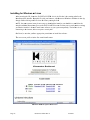
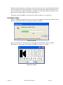
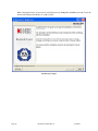
Installation Steps...................................................................................................................................................... 53
Additional Installation notes .................................................................................................................................... 57
Running ROCKTalk ................................................................................................................................................ 58
Running Rockhound on your computer ................................................................................................................... 58
5. Rockhound Modules .............................................................................................................................................. 61
Available categories and modules ........................................................................................................................... 61
Configuration information common to all Rockhound layouts ............................................................................... 64
Multichannel source for data ................................................................................................................................... 65
Altus SDS Input from TCP/IP............................................................................................................................ 65
Altus SDS Input from RS232 ............................................................................................................................. 73
Q330 Input from UDP/IP ................................................................................................................................... 79
Rock Data Interface ............................................................................................................................................ 88
MZD24 Data Interface ..................................................................................................................................... 113
TSASMA Data Interface .................................................................................................................................. 129
Ring Buffer Data Interface .............................................................................................................................. 140
Pseudo Data Waveform Generator (Advanced) ............................................................................................... 145
Data multichannel integrator ................................................................................................................................. 151
Data Integrator ................................................................................................................................................. 151
Status integrator ..................................................................................................................................................... 153
Status Integrator ............................................................................................................................................... 153
Channel extractor ................................................................................................................................................... 153
Channel Extractor ............................................................................................................................................ 153
Channel trigger filter ............................................................................................................................................. 153
Classic Strong Motion Filter ............................................................................................................................ 154
IIR-A Filter ....................................................................................................................................................... 155
IIR-C Filter ....................................................................................................................................................... 156
LPSRO Filter (Advanced) ................................................................................................................................ 157
LPWWSS Filter (Advanced) ............................................................................................................................. 158
GS21 Filter (Advanced) .................................................................................................................................... 159
SPWWSS Filter (Advanced) ............................................................................................................................. 159
Channel trigger ...................................................................................................................................................... 160
Threshold Trigger ............................................................................................................................................. 160
STA/LTA Trigger .............................................................................................................................................. 161
Channel data filter ................................................................................................................................................. 164
DIY FIR Filter (Advanced) .............................................................................................................................. 164
DIY IIR Filter (Advanced) ............................................................................................................................... 165
Velocity IIR Filter (Advanced) ......................................................................................................................... 167
Displacement IIR Filter (Advanced) ................................................................................................................ 168
Post-Integration IIR Filter (Advanced) ........................................................................................................... 169
Voter ...................................................................................................................................................................... 170
Voter .................................................................................................................................................................. 170
CGS Voter ......................................................................................................................................................... 171
Event recorder........................................................................................................................................................ 172
Recorder ............................................................................................................................................................ 172
Continuous recorder .............................................................................................................................................. 173
Continuous Recorder ........................................................................................................................................ 173
File data formatter and archiver ............................................................................................................................. 174
MiniSeed Format Data Archiver ...................................................................................................................... 174
SAC Format Data Archiver .............................................................................................................................. 176
COSMOS Format Data Archiver ..................................................................................................................... 178
MATLAB Format Data Archiver ..................................................................................................................... 180
SEISAN Format Data Archiver ....................................................................................................................... 180
Altus EVT Format Data Archiver .................................................................................................................... 183
Text Format Data Archiver .............................................................................................................................. 186
SUDS Format Data Archiver ........................................................................................................................... 188
SEISLOG Format Data Archiver ..................................................................................................................... 190
Link to external data source ................................................................................................................................... 191
NMS Queue Monitor ........................................................................................................................................ 191
Auto File sender..................................................................................................................................................... 192
FTP File Sender ............................................................................................................................................... 192
SCP File Sender ................................................................................................................................................ 194
E-Mail File Sender ........................................................................................................................................... 196
Command console ................................................................................................................................................. 199
Command console ............................................................................................................................................. 199
System monitoring utilities .................................................................................................................................... 205
Update monitor ................................................................................................................................................. 206
Status Display GUI ................................................................................................................................................ 208
Status Display GUI (Desktop Only) ................................................................................................................. 208
PGA Alarms Display GUI (Desktop Only) ....................................................................................................... 211
Status serving utilities ............................................................................................................................................ 214
Status Server ..................................................................................................................................................... 214
Auto file delete scanner ......................................................................................................................................... 214
Aged Auto File Delete ....................................................................................................................................... 214
Auto Oldest File Delete ..................................................................................................................................... 215
Auto Small EVT File Delete ............................................................................................................................. 217
Statistics generator ................................................................................................................................................. 218
Run Time Parameter Statistics ......................................................................................................................... 218
Summary File Generator .................................................................................................................................. 219
JMA Summary File Generator......................................................................................................................... 221
SOH File Generator ......................................................................................................................................... 224
Web Server ............................................................................................................................................................ 225
Config/Control web server ................................................................................................................................ 226
Telemetry connections ........................................................................................................................................... 241
Waveform viewer .............................................................................................................................................. 241
Data Relay to transmit data stream ........................................................................................................................ 242
DFS Telemetry (Advanced) .............................................................................................................................. 242
SVDR Telemetry (Advanced)............................................................................................................................ 244
Altus Telemetry via RS-232 .............................................................................................................................. 247
Altus Telemetry via TCP/IP .............................................................................................................................. 253
CGS Altus Telemetry via RS-232 ..................................................................................................................... 258
CGS Altus Telemetry via TCP/IP ..................................................................................................................... 264
PPP Dial Generation ........................................................................................................................................ 269
QSCD Packet Telemetry ................................................................................................................................... 270
Local mirror of a data source ................................................................................................................................. 276
SEEDLink Stream Mirrored to Disk ................................................................................................................ 276
Ring Buffer Server................................................................................................................................................. 277
Ring Buffer Server ............................................................................................................................................ 277
Timed event alarm clock ....................................................................................................................................... 281
Alarm Clock ...................................................................................................................................................... 281
User notifier ........................................................................................................................................................... 283
E-Mail Message Sender .................................................................................................................................... 283
SMS Message Sender........................................................................................................................................ 288
File Forwarder .................................................................................................................................................. 292
Interconnect facilities ............................................................................................................................................ 293
Network Trigger ................................................................................................................................................ 293
General Purpose IO interface................................................................................................................................. 296
Rock GPIO ........................................................................................................................................................ 296
Rock PGA GPIO ............................................................................................................................................... 299
OASIS Display GUI .............................................................................................................................................. 306
OASIS Display GUI (Desktop Only) (Advanced) ............................................................................................ 306
OASIS Data bridge ................................................................................................................................................ 307
OASIS Data Bridge (Advanced) ....................................................................................................................... 307
Mathematical integration of data (A-->V-->D) ..................................................................................................... 311
OASIS Mathematical Integrator (Advanced) .................................................................................................. 311
Computes drift between specified displacement channels ..................................................................................... 311
OASIS Drift Computer (Advanced).................................................................................................................. 311
OASIS Statistics generator .................................................................................................................................... 313
OASIS Statistics Generator .............................................................................................................................. 313
OASIS drift trigger ................................................................................................................................................ 315
OASIS Drift trigger (Advanced) ....................................................................................................................... 315
OASIS Alarm controller ........................................................................................................................................ 317
OASIS Alarm controller module (Advanced) .................................................................................................. 317
Channel pre-extractor ............................................................................................................................................ 318
Channel Pre-Extractor ..................................................................................................................................... 318
Data processing plug-ins........................................................................................................................................ 318
Data Plug-in Layout ......................................................................................................................................... 320
6. Network Management ......................................................................................................................................... 321
FTP Server Considerations .................................................................................................................................... 321
Using existing Altus recorders with Rockhound ................................................................................................... 321
Delivery of recorded files ...................................................................................................................................... 322
Notifying the user from Rockhound ...................................................................................................................... 322
Upgrading Rockhound firmware ........................................................................................................................... 322
Upgrading Rockhound configuration .................................................................................................................... 323
7. Troubleshooting ................................................................................................................................................... 325
Rockhound Starts and Crashes in a Loop .............................................................................................................. 325
Rockhound Stops Working After 12 Hours ........................................................................................................... 326
Advanced Features not Accessible ........................................................................................................................ 327
1. Introduction
This manual covers the Kinemetrics Rockhound software.
General Information
Rockhound is a product designed to process data from one or more digitizers, performing the functions on
that data that are needed by the end user. These functions can include among many other capabilities:
- Continuous recording
- Triggered event recording
- Storage management
- Telemetry reformatting and relaying
- Data delivery
- Data post processing
Rockhound is delivered in primarily three forms:
- As a turn-key low power hardware and firmware package
- As a turn-key high capability hardware and firmware package
- As a firmware only product
Contact Kinemetrics to determine which Rockhound product best suits your particular needs.
The Rockhound firmware design is highly modular. These modules may be connected together in many
different ways. Written in Java, the firmware can also be run on a variety of platforms, including
MicroSoft's Windows Operating Systems, Sun MicroSystems' Solaris Operating System, and the Linux
Operating System.
Contact Kinemetrics for further information on compatibility of Rockhound with other platforms.
This modular approach also provides other significant benefits:
- New Rockhound modules can be created and added with little or no impact on the rest of the Rockhound
system.
- Rockhound modules can often be tested in near isolation, improving the speed and accuracy of testing.
6/20/2011
Document 304702 Rev N
Page 1
Definitions
The following terms are used throughout this manual:
SMARTSID - The SMARTSID is a unique name assigned to this unit. The name is stored in hardware.cfg
so that it is kept separate from parameters that might be shared with other units.
Broadcast - A method of notification that allows a Rockhound module to transmit a notification that
something has occurred. One or more listening modules may then act upon the broadcast, or the broadcast
may be ignored. An example would be event notification through pager or e-mail, where the "event start"
and "event end" notifications are broadcast by the EventRecorder module but whether or not these
notifications are acted upon depends on what modules have been included to handle that notification. (See
the section on User Notifiers).
Command Console - The Command Console is a special Rockhound Module that is required in all
Rockhound Layouts. The console is used to allow other computers to connect to Rockhound at a specific IP
Port for the purpose of sending operational instructions to Rockhound. (See the section on the Command
Console later in this manual)
Data filters - Data filters are used to process the data stream for the purpose of altering the data before
recording or transmission. A data filter differs from a trigger filter in that a trigger filter affects only a
trigger but does not affect the recorded data itself. Data filters are generally implemented using a plug-in
mechanism, and consists of a data processing activity for doing the filtering. Data filters as used in plug-ins
can consist of multiple filtering stages. Data filters are usually used for anti-alias filtering, or to reduce the
sample rate (and thus the volume of the data) before storage or transmission.
Dialog - A dialog is a window that pops up during use of a program. A dialog is usually used to allow the
user to make a choice, such as selecting between several available options. Dialogs can be as simple as an
"Are you sure you want to do this?" choice, to something as complex as a complete review of configuration
settings.
DigitizerId - A digitizer name used to identify data as it flows through Rockhound. This is an internal name
that is used only within Rockhound to route data from one of perhaps several digitizers through the different
parts of the Rockhound firmware. If several units have the same layout, with the same type and number of
digitizers, they may all use the same DigitizerIDs internally. This may help aid the user in sharing
configuration information between multiple units that are otherwise identical.
Firmware - In general, firmware is dedicated software that is stored in solid state devices, within an
instrument or appliance. In the context of Rockhound, "firmware" is used to refer to the software that
actually runs on Rockhound itself to help differentiate it from other software such as KMI's ROCKTalk or
other third party software. (See Software).
GUI - Graphical User Interface. A user interface based on graphical (not simply text based) and usually
mouse driven designs. The most common example is a "Windows" program with its menus, tool bars, and
push buttons versus the old style "DOS" programs with entirely text mode interfaces.
IP Address - An "Internet Protocol" address, which defines a computer uniquely on the Internet or on a
Local Area Network. IP Addresses usually have the form xxx.xx.xx.xx, such as 127.0.0.1. The address
127.0.0.1 is a special address that a computer may use to refer to itself.
Page 2
Document 304702 Rev N
6/20/2011
IP Port - A data path within an "Internet Protocol" connection. Typically, one IP Address will be accessed
at many IP Ports. IP Ports 5000 and below are defined for standard purposes such as Telnet, E-mail, and
FTP. IP Ports above 5000 can be defined as needed by programs such as Rockhound. Rockhound requires
the use and definition of several IP Ports, each of which is defaulted to a value that should be useable in
most applications. Typically, Rockhound IP Port defaults are 9000 and above.
JAR - A JAR file is a facility provided by the Java programming language for putting several files together
into one file for compression and/or ease of handling. In many ways, JAR files are similar to ZIP files that
have been used for years by PC users. The difference is that JAR files will work the same way on different
computing platforms just as the Java language will.
Java - A language developed by Sun MicroSystems, Inc. that allows programs to be written once, and with
some care in the design, to be run on any computing platform for which there is a JVM available (see
below). Kinemetrics has chosen to write the Rockhound firmware and software in Java so that Rockhound
may be run on Linux, Windows, Solaris, and other computing platforms.
JVM - Java Virtual Machine. The JVM is a software layer that provides the interface between a Java
program and the host operating system. Running any Java program requires the installation of the
appropriate JVM.
Layout - A collection of modules included in a unit. Which modules are used, how many of each type are
used, and how the modules are connected to produce the desired results are all defined by the layout.
Module - In general, a portion of a larger whole. In the context of Rockhound, a Rockhound module (or
sometimes simply "module") is a portion of the Rockhound firmware with very specific responsibilities.
Modules of differing types are combined to process data through Rockhound and for side calculations such
as triggering.
Plug-in - A Plug-in is a method of data handling within a Rockhound module that supports optional data
processing methods. A plug-in is not a Rockhound module, and is usually used for higher data rate activities
such as data filtering. Plug-ins are an advanced topic, and are more complex than configuring and operating
basic Rockhound. See Plug-in Files and Plug-in Layout Files sections.
Publication - The Rockhound firmware is primarily designed around a "publication/subscription" model.
This means that most modules take data in from one or more modules elsewhere in Rockhound layout that
they have "subscribed" to. Data coming from other sources that this module has not subscribed to is
ignored. Once processed, a module will generally "publish" results for consumption by still other modules.
Reply - The returned results of a Request. See "request".
Request - A special variation of the subscription/publication interface that allows a module to make a
specific request for information, and to have the results of that request returned via a "reply". In Rockhound,
the best example of this "request/reply" method is the interface between a DataIntegrator which contains the
pre-event memory buffers and an EventRecorder, that once triggered, will request the data to be recorded.
Rockhound - The library of Kinemetrics Rockhound code that can be assembled to provide great
flexibility.
Software - In general, software is a set of instructions to a computer. When users think of software, they
tend to think of software stored on hard disks or other such media. In the context of Rockhound, "software"
6/20/2011
Document 304702 Rev N
Page 3
is not used to refer to the software that actually runs the unit, but to user interface software such as
ROCKTalk or to other software for processing or handling the resulting data. (See Firmware)
Subscription - The primary method used for Rockhound modules to accept data from other Rockhound
modules. See "publication".
Unit - A target hardware platform, either provided by Kinemetrics or by the customer that is used for
running the Rockhound firmware. In many cases, this is a box in the field.
Widget - A widget is a component of a GUI display. Widgets can include buttons, checkboxes, pull-down
lists, text areas, scroll bars, and other items.
Overview
The Rockhound firmware and software model consists of the following components:
- The Operating System: This is the basic computer software that provides the management of the
computer's services. Because Rockhound is written in Java, Rockhound is not limited to any one
Operating System. Rockhound code will run on multiple Operating Systems. Contact Kinemetrics for a
complete list. The Operating System is typically a separate commercial product that must be purchased
or obtained separately.
- The Java Virtual Machine, or JVM: The JVM provides the environment in which the compiled Java
code of Rockhound operates. The JVM isolates the Rockhound code from the details of the particular
computer or Operating System employed. As of this writing, Rockhound is written for Sun's 1.4 JVM
or later.
- The Rockhound Firmware: This is the firmware that performs the actual functions of the unit. The exact
functions depend on what modules were selected and how the modules were connected. This firmware
will be updated by Kinemetrics regularly as capabilities are added to the overall Rockhound system,
and as user requirements, data sources, or other factors dictate changes.
- Rockhound Support Software: Also written in Java, support for Rockhound includes ROCKTalk, a
utility that allows the user to quickly and easily configure Rockhound for the most commonly used
applications. Other support utilities are provided as well.
- Configuration Data: If a turn-key system is purchased, configuration data will be created for a standard
implementation of Rockhound. In most cases, it will be necessary to reconfigure Rockhound using
ROCKTalk to fit individual needs. If Rockhound is purchased as a firmware only package, this initial
configuration information will be created by the end user.
Rockhound is made up of modules that process data flowing through Rockhound in a uniform way. These
modules may be connected to one another to split, combine, process, record, or transform data using a
number of different methods.
Page 4
Document 304702 Rev N
6/20/2011
The Ba
asics of Rockhoun
R
nd Modulles
Rockhound
R
mo
odules comm
municate with each other ussing a very staandardized innterface. In geeneral, a
Rockhound
R
mo
odule sends and/or
a
receivees data and meessages to or from other R
Rockhound moodules.
The
T examples in the followiing section arre intended onnly to introduuce the generaal concept of Rockhound
modules.
m
The details
d
of mod
dules are desccribed later inn the manual in a section thhat addresses each modulee.
wever, the
Most
M modules are optional depending
d
on
n the applicatiion. Two moddule types how
CommandCon
C
nsole and the UpdateMonit
U
tor, are requirred in all Rockkhound layouuts and are inccluded
au
utomatically whenever
w
a Rockhound
R
lay
yout is createed. These two modules are not describedd in this
in
ntroductory seection.
A Rockhound module Publlishes output data or messaages to other Rockhound m
modules intereested in its
ou
utput.
A Rockhound module Subsscribes to datta or message s from other R
Rockhound m
modules that iit wants data
frrom.
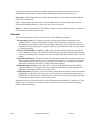
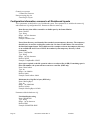
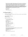
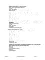
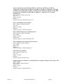
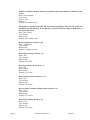
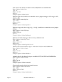
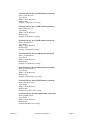
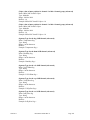
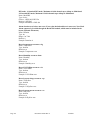
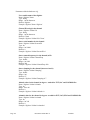
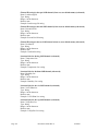
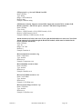
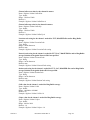
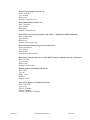
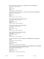
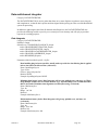
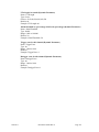
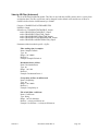
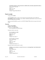
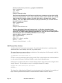
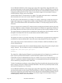
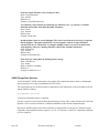
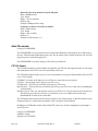
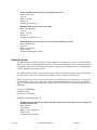
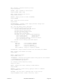
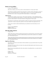
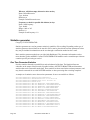
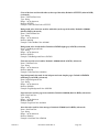
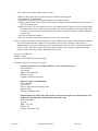
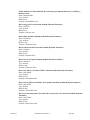
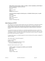
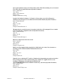
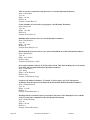
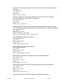
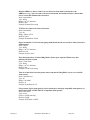
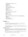
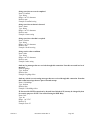
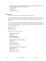
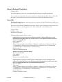
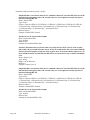
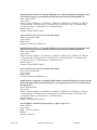
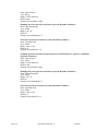
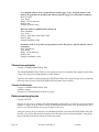
For example, here's
h
a simple example off three modulees:
- DATASOUR
RCE is a sourcce of unfiltereed data
- FILTER is a module that filters
f
the dataa in some wayy
- TRIGGER iss a trigger actiing on the filttered data
Basic Mo
odule Relation
nships
For each modu
ule in the Rocckhound confi
figuration, thee module layoout file layoutt.cfg defines tthe type of
module,
m
the naame of the module, any pub
blications of thhe module (O
Output is assum
med), and anyy subscriptions
th
he module usees. Note that a module may
y publish multtiple messagees for use by vvarious subscrriber moduless,
an
nd a module may
m subscribee to multiple messages froom other modu
dules.
In
n addition, each module haas a configuraation file that defines the value of any parameters useed by the
module.
m
In mo
ost cases, paraameters of a module
m
are onnly of interestt to one particcular module, and if shared
d
ou
utside of the module
m
at all are only sharred on an as-nneeded basis.
For example, a threshold triigger module will define pparameters forr the trigger leevel, detriggeer level, and
nu
umber of votees for that streeam of data in
n its configurration file. If tthe module is named Chan
nnel1Triggerr,
th
hen the config
guration file will
w be called config/Chan
nnel1Triggerr.cfg.
Each
E
module is assigned a debugging
d
lev
vel. This is a hhexadecimal bit mask for each module in the layout.
The
T debugging
g bits are used
d for Kinemetrrics' internal ttesting and deebugging, andd are not intennded for use by
y
th
he customer. Debugging
D
in
nformation is stored in the file debug.cffg.
6/20/2011
Document 304702 Rev N
Page 5
Rockhound
R
wiide parameters, those that are
a expected tto be used by multiple moddules within thhe Rockhound
d
sy
ystem, are sto
ored in smarts.cfg. This fille would holdd parameters ssuch as the iddentifying nam
me of the unitt,
pllus widely neeeded parametters such as PreEvent
P
and PostEvent tim
me if Rockhouund is being uused for even
nt
reecording.
Lastly,
L
hardwaare specific paarameters are stored in the configurationn file hardwaare.cfg. This file is used to
o
ho
old values thaat are unique to
t a particularr set of hardw
ware, and would include succh things as seerial numberss,
ch
hannel countss, sensor types, calibration values, and oother things thhat are particuular to a givenn set of
haardware.
The
T idea is to separate
s
the hardware
h
speccific parts of tthe configuraation from thoose that are noot hardware
deependent, so that
t common Rockhound configuration
c
ns can be usedd at multiple ssites having ssimilar overall
reequirements.
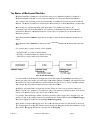
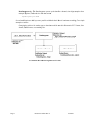
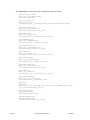
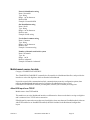
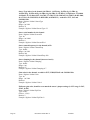
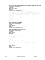
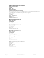
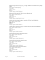
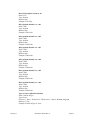
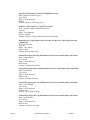
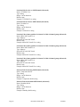
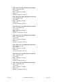
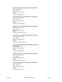
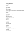
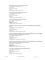
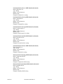
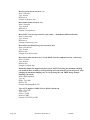
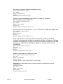
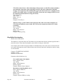
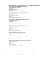
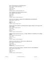
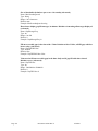
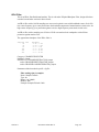
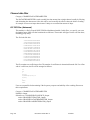
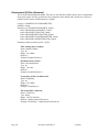
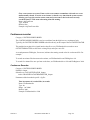
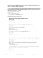
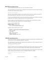
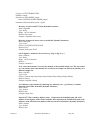
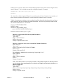
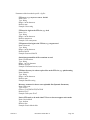
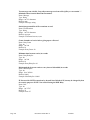
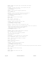
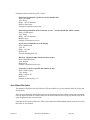
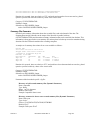
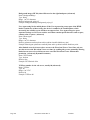
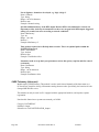
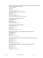
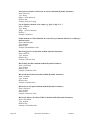
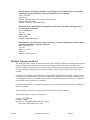
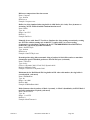
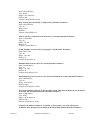
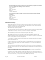
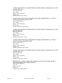
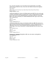
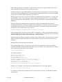
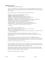
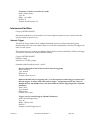
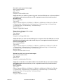
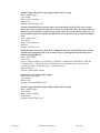
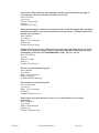
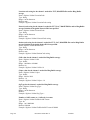
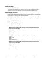
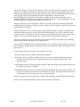
A More Complete Example - Continuo
ous Record
ding
OK,
O we've reviewed the bassics of how Rockhound
R
moodules hook ttogether, so leet's look at a m
more realisticc,
bu
ut still relativ
vely simple ex
xample. Let's look at a Rocckhound conffiguration witth the followinng
ch
haracteristics:
- Input data sou
urce is a Kineemetrics Altu
us recorder useed as a digitizzer (sample raate unimportaant for this
example)
- Data is to be recorded con
ntinuously in 15
1 minute (9000 second) filles
- Data is to be stored in Min
niSEED form
mat
A Simple Contin
nuous Record
der Example
As
A shown, dataa flows from the data source, to the conntinuous recorrder module tthat is responssible for
gaathering all of the data from
m the data source and neattly dividing itt into 15 minuute (900 seconnd) segments.
The
T data is theen in turn passsed to the Arcchiver that is responsible fo
for formattingg it in the selected style - in
n
th
his case MiniS
SEED formatt.
Page 6
Document 304702 Rev N
6/20/2011
The layout.cfg file that describes this simple configuration appears as follows:
Type=AltusTCPFrontEnd
Name=_dig1_1_AltusTCPFrontEnd
SubscribesTo=NOTHING
Type=DataIntegrator
Name=DataIntegrator
SubscribesTo=_dig1_1_AltusTCPFrontEnd_Output
Type=ContinuousRecorder
Name=ContinuousRecorder
SubscribesTo=DataIntegrator_Output
Type=MiniSeedArchiver
Name=MiniSeedArchiver
SubscribesTo=ContinuousRecorder_Output
The smarts.cfg file that describes this configuration would contain no data, and be blank.
The hardware.cfg file that describes this configuration appears as follows:
SMARTSId=KMI
NetworkId=KMI
NChannels=3
dig1.Name=dig1
dig1.TCPPort=9001
dig1.Host=127.0.0.1
dig1.ch1.Id=C1
dig1.ch2.Id=C2
dig1.ch3.Id=C3
RetrySeconds=300
The various module specific configuration files appear as follows:
_dig1_1_AltusTCPFrontEnd.cfg - Reads SDS data from an Altus digitizer
Compress=true
Channels=1,2,3
NDigitizerChannels=3
DigitizerId=dig1
SPS=100
Buffer=64
ContinuousRecorder.cfg - Multichannel data recorder (format independent) that records
continuously
FileDurationSec=900
MiniSeedArchiver.cfg - Data output formatter that records the data in MiniSeed format
Channels=*
ScaleDivisor=1.0
DirLayout=FLAT
OutputDir=\\data\\events\\
6/20/2011
Document 304702 Rev N
Page 7
DataInteg
grator.cfg - The
T DataInteg
grator queues up the data ffor a channel, time aligns ssamples from
multiple digitizers,
d
and
d sends it to th
he data stream
m.
Input
tPluginLayout=NONE
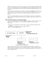
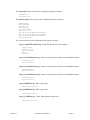
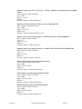
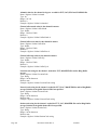
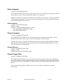
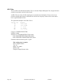
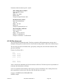
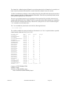
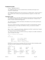
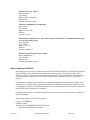
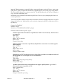
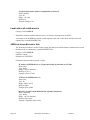
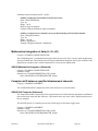
Several modifiications to thiis layout are possible
p
withiin the basic iddea of continuuous recordingg. Two simple
ex
xamples would be:
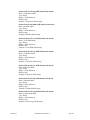
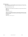
Changing the archiver for another ty
ype so that daata could be sttored in Kinemetrics EVT format, SAC
C
format, SU
UDS format, or something else:
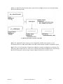
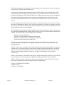
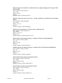
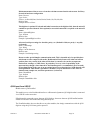
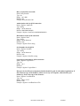
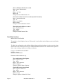
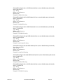
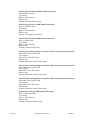
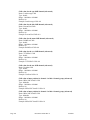
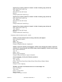
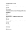
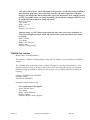
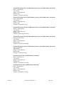
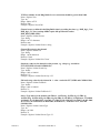
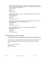
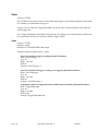
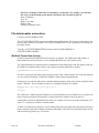
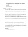
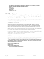
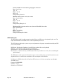
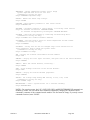
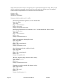
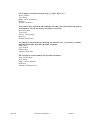
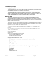
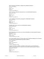
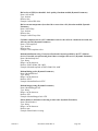
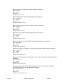
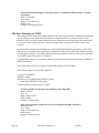
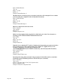
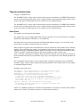
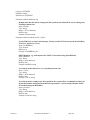
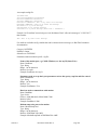
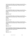
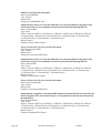
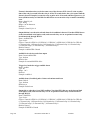
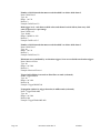
A Continuous Record
der Storing D
Data as EVT Files
Page 8
Document 304702 Rev N
6/20/2011
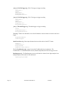
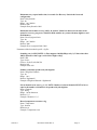
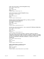
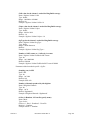
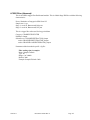
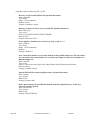
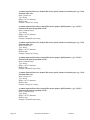
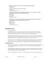
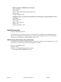
Adding
A
a secon
nd front end so
s that data caan be gathereed from two ddigitizers (not necessarily ttransmitting
daata at the sam
me sample ratee):
A Con
ntinuous Reco
order From Tw
wo Front End
ds
Note
N
1: For a description
d
off the meaning
g of each conffiguration varriable in the eexamples, see the
do
ocumentation
n later on in th
his manual thaat describes thhe available m
modules and ttheir configurration optionss.
Note
N
2: These are relatively
y simple confi
figurations. M
Much more com
mplex configgurations are ccommon. We
will
w look at oth
her examples later on. The process of crreating most ccommon conffigurations is automated by
y
th
he ROCKTalk
k program, so
o increasingly
y complex exaamples shouldd not be causee for concern.
6/20/2011
Document 304702 Rev N
Page 9
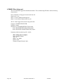
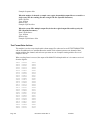
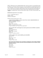
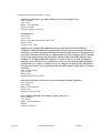
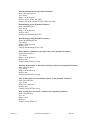
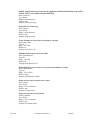
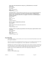
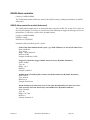
A More Detailed Example - Event Triggered Recording
Event triggered recording results in a more complex example, because in addition to the requirement for a
data source, a data integrator, and a format specific archiver, we now need to add trigger filters, triggers, a
voter, and an event recorder that can deal with pre-event and post-event memory.
In this example, we'll create a configuration with the following characteristics:
- Input data source is a Kinemetrics Altus recorder used as a digitizer (again, sample rate is not important for
the purposes of the example)
- IIR-A trigger filters are used on channels 1 and 2
- A Kinemetrics "Classic Strong Motion" trigger filter is used on channel 3
- STA/LTA triggers are used on channels 1 and 2
- A threshold trigger is used on channel 3
- Two votes are required to trigger the system
- Ten seconds of pre-event memory is used
- Thirty seconds of post-event memory is used
- Data is to be stored in Kinemetrics EVT format
Page 10
Document 304702 Rev N
6/20/2011
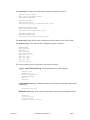
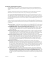
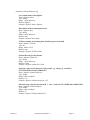
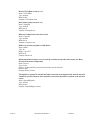
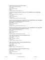
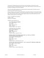
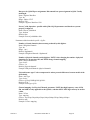
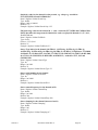
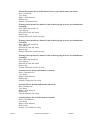
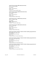
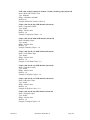
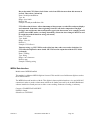
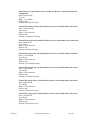
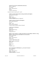
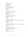
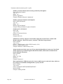
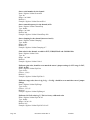
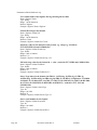
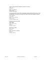
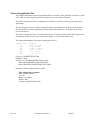
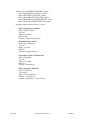
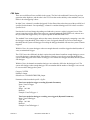
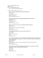
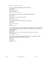
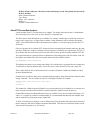
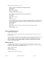
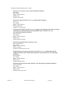
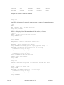
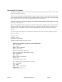
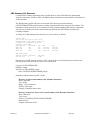
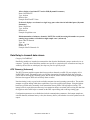
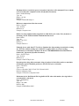
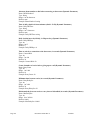
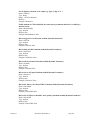
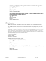
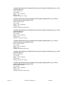
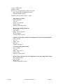
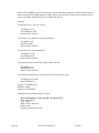
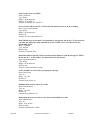
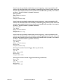
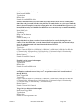
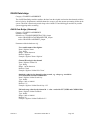
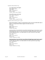
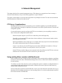
nt Recorder E
Example
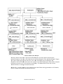
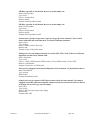
A Basic Even
Note
N here that the data streaam is split fro
om the DataInntegrator into three channel streams by tthe
ChannelExtrac
C
ctors. From th
here, each chaannel stream iis passed throuugh a Filter, aand then throuugh a Triggerr.
The
T output of the
t Triggers are
a all sent to the Voter, wh
who will indicaate start of reccording to thee
EventRecorder
E
r. The EventR
Recorder mak
kes data requeests back to thhe DataIntegrator that provvides adequatee
bu
uffering to prrovide for pre-event and po
ost-event mem
mory. The retu
turned data is then sent on to the
AltusEvtArchi
A
iver for storag
ge in the desirred format.
Realistically,
R
it would probaably be more natural to usee similar filteers and triggerr methods on all channels,
bu
ut this examp
ple demonstraates Rockhoun
nd flexibility..
6/20/2011
Document 304702 Rev N
Page 11
The layout.cfg file that describes this configuration appears as follows:
Type=AltusTCPFrontEnd
Name=_kmi_1_AltusTCPFrontEnd
SubscribesTo=NOTHING
Type=DataIntegrator
Name=DataIntegrator
SubscribesTo=_kmi_1_AltusTCPFrontEnd_Output EventRecorder_Request
Type=ChannelExtractor
Name=_kmi_1_ChannelExtractor
SubscribesTo=DataIntegrator_Output
Type=IIRAFilter
Name=_kmi_1_IIRAFilter
SubscribesTo=_kmi_1_ChannelExtractor_Output
Type=STALTATrigger
Name=_kmi_1_STALTATrigger
SubscribesTo=_kmi_1_IIRAFilter_Output
Type=ChannelExtractor
Name=_kmi_2_ChannelExtractor
SubscribesTo=DataIntegrator_Output
Type=IIRAFilter
Name=_kmi_2_IIRAFilter
SubscribesTo=_kmi_2_ChannelExtractor_Output
Type=STALTATrigger
Name=_kmi_2_STALTATrigger
SubscribesTo=_kmi_2_IIRAFilter_Output
Type=ChannelExtractor
Name=_kmi_3_ChannelExtractor
SubscribesTo=DataIntegrator_Output
Type=CSMFilter
Name=_kmi_3_CSMFilter
SubscribesTo=_kmi_3_ChannelExtractor_Output
Type=ThresholdTrigger
Name=_kmi_3_ThresholdTrigger
SubscribesTo=_kmi_3_CSMFilter_Output
Type=Voter
Name=Voter
SubscribesTo=_kmi_1_STALTATrigger_Output _kmi_2_STALTATrigger_Output
_kmi_3_ThresholdTrigger_Output
Type=EventRecorder
Name=EventRecorder
SubscribesTo=Voter_Output
Type=AltusEvtArchiver
Name=AltusEvtArchiver
SubscribesTo=EventRecorder_Output
Page 12
Document 304702 Rev N
6/20/2011
The smarts.cfg file that describes this configuration appears as follows:
PreEventSec=3
PostEventSec=10
The hardware.cfg file that describes this configuration appears as follows:
SMARTSId=KMI
NetworkId=KMI
NChannels=3
kmi.Name=dig1
kmi.TCPPort=9001
kmi.Host=127.0.0.1
kmi.ch1.FullScaleADCCounts=8388608
kmi.ch2.FullScaleADCCounts=8388608
kmi.ch3.FullScaleADCCounts=8388608
RetrySeconds=300
The various module specific configuration files appear as follows:
_kmi_1_AltusTCPFrontEnd.cfg - Reads SDS data from an Altus digitizer
Compress=true
Channels=1,2,3
DigitizerId=kmi
SPS=100
Buffer=64
_kmi_1_ChannelExtractor.cfg - Extracts a single channel of data from multichannel output
ChannelNumber=1
DigitizerId=kmi
_kmi_2_ChannelExtractor.cfg - Extracts a single channel of data from multichannel output
ChannelNumber=2
DigitizerId=kmi
_kmi_3_ChannelExtractor.cfg - Extracts a single channel of data from multichannel output
ChannelNumber=3
DigitizerId=kmi
_kmi_1_IIRAFilter.cfg - IIR-A trigger filter
SamplesToSettle=3000
_kmi_2_IIRAFilter.cfg - IIR-A trigger filter
SamplesToSettle=3000
_kmi_3_CSMFilter.cfg - Classic Strong Motion trigger filter
SamplesToSettle=3000
6/20/2011
Document 304702 Rev N
Page 13
_kmi_1_STALTATrigger.cfg - STA/LTA trigger to trigger recording
STALength=1.0
Votes=1
LTALength=60
TriggerRatio=4.0
DetriggerPercent=40.0
_kmi_2_STALTATrigger.cfg - STA/LTA trigger to trigger recording
STALength=1.0
Votes=1
LTALength=60
TriggerRatio=4.0
DetriggerPercent=40.0
_kmi_3_ThresholdTrigger.cfg - Threshold trigger to trigger recording
Votes=1
TriggerThreshold=2.0
DetriggerThreshold=2.0
Voter.cfg - Channel voter that tallies votes from all channels to decide whether or not there has been a
trigger
TriggerWindowMS=800
VotesToTrigger=2
AltusEvtArchiver.cfg - Data output formatter that records the data in Altus EVT format
Channels=*
ScaleDivisor=1.0
DirLayout=FLAT
OutputDir=\\data\\events\\
The file EventRecorder.cfg is empty because the EventRecorder has no parameters. The
EventRecorder is a multichannel data recorder (format independent) that records a triggered event.
DataIntegrator.cfg - The DataIntegrator queues up the data for a channel, time aligns samples from
multiple digitizers, and sends it to the data stream.
InputPluginLayout=NONE
Page 14
Document 304702 Rev N
6/20/2011
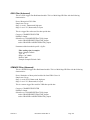
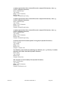
Rockhound and ROCKTalk Passwords
In the following sections, you will see a lot of discussion about passwords. The Rockhound firmware,
ROCKTalk, and the Q330 make use of these passwords in various ways to protect various parts of your
system.
In general, passwords keep the curious or the casual hacker out of an area where they are not wanted.
Passwords are not secure, but in many cases they are "good enough" given the alternatives.
In a typical Q330/Rockhound/ROCKTalk application, there may be several passwords in use at any one
time. Although it is possible to eliminate many of these passwords for ease of use and leave your system
"wide open", Kinemetrics does not recommend this. The other alternative is to implement all passwords and
have different password values for each - this is more complex, but also probably the most secure use of
passwords alone.
As an overview, the passwords available for possible use in a Q330/Rockhound/ROCKTalk application are
listed here. Note that exactly which passwords you will need or use will depend on how your overall system
is configured:
Q330 Serial Number - The Q330 has a long serial number, such as '01000001DEC25E78', which is part of
the registration with the Q330. It is used in conjunction with the Q330 Authorization code to register
with the Q330 remotely. This value is required and is unique to each Q330.
Q330 Authorization Code - The Q330 has an authorization code which is required in order to make a
connection to the Q330. Computers that are to communicate with the Q330 must "register" using this
code and the Q330 serial number before a connection is established. This value is required and is
unique to each Q330.
Rockhound Authorization Code - Rockhound has an authorization code that is assigned by Kinemetrics
and is provided either with turnkey Rockhound hardware, or for use with your computers if you are
using Rockhound firmware on your own computer. Without this authorization code, Rockhound will
only run in demo mode for up to 12 hours. This value is required and is unique to each unit.
Rockhound CommandConsole Password - The Rockhound CommandConsole, which is a command line
interface to Rockhound, includes support for a password. Since the CommandConsole behaves very
much like a Telnet connection for ease of use, it should be protected with a password. The Console
password can be entered for each unit in the ROCKTalk Setup dialog to automate sending of the
password to the Rockhound CommandConsole. This password is set to a default value, but use of a
password is not required.
Rockhound SCP/FTP Password - Kinemetrics' Rockhound turn-key systems, which consist of
Rockhound firmware loaded onto Kinemetrics' hardware, run under the Linux operating system. As
Rockhound records files, they will be stored on the provided storage media. Linux provides a secure
SCP server which is always enabled, and an FTP server, which can be enabled to allow users to retrieve
files remotely using an FTP transfer program - including use of most popular Internet browsers. The
SCP/FTP password restricts those users that can retrieve, change, or delete files. An SCP/FTP
password is set by default, but is not required.
User and Root Passwords - Kinemetrics' Rockhound turn-key systems, which consist of Rockhound
firmware loaded onto Kinemetrics' hardware, run under the Linux operating system. Linux provides
password protected user accounts, including a "root" account for system administration activities, plus
two Rockhound specific accounts that are used for execution of the Rockhound firmware and
configuration of Rockhound. In addition, the user may choose to install his own accounts, which may
have their own passwords. Passwords on the various Linux user accounts are set by default, but are not
required.
6/20/2011
Document 304702 Rev N
Page 15
ROCKTalk Advanced User Password - ROCKTalk allows for restriction of Advanced User features.
The Advanced User password is set on the ROCKTalk Setup dialog. By default, no Advanced User
password is set.
FTP Server Password - In addition to the unit acting as an SCP/FTP Server allowing remote retrieval of
files, Rockhound can transmit files automatically to an FTP Server that the user has set up to accept
these files. Setup and maintenance of an FTP Server is the responsibility of the user if desired.
Normally, the FTP Server would have accounts and passwords to restrict reading, writing, or changing
of files on the FTP Server. The FTP Server's address, account name, and password must be given to the
Rockhound FTPSender module in the form of parameters. See FTPSender Rockhound module.
Default Passwords
Passwords are set for various parts of Rockhound and ROCKTalk system by default. These default
passwords are listed here for your convenience in getting started. Please note that the trade-off in listing the
passwords for your convenience is that these passwords are then not secure. You are encouraged to
change the passwords to private settings.
Rockhound Administration: Account name admin, password kmi - The administration password used
for firmware and configuration updates. This is the account and password that should be used as the
"SCP/FTP login name and password" for ROCKTalk to communicate with Linux based hardware via
SCP/FTP. This password can be changed via the Linux "passwd" command from the Linux admin
account.
Rockhound Client: Account name client, password kmi - A client account used for READ ONLY
access to the Linux based SCP/FTP server when using SCP or in the event that FTP is used and
anonymous FTP access is disabled. This account has wider access than the anonymous login, and can
traverse other Linux directories beyond limited to the /pub directory. To access the SCP/FTP site with
write access, such as to delete files, you must log into the unit's SCP/FTP server using the admin
account. This password can be changed via the Linux "passwd" command from the Linux client
account.
Rockhound Command Console Password: Q330 - The password used to control access to the
Rockhound Command Console. This password must be set in two places, in the Rockhound Command
Console configuration parameters and in ROCKTalk's Command Console parameter under
ROCKTalk Setup.
Anonymous FTP: Account name anonymous, password emailaddress - This account is provided by
default for anonymous READ ONLY access to the Linux based FTP server. To access recorded files
anonymously, log into the FTP site using this account and your e-mail address as a password. To log
into the SCP/FTP site with write access, use the admin account. Files are typically stored under
/pub/data/events/
In higher security applications, a better protection method is use of "secure" communications functions,
such as secure shell, secure telnet, and SCP. These methods are significantly more complicated, and use
encryption that makes the data meaningless to anyone "sniffing" the connection, and denies unauthorized
connections to your system totally.
Page 16
Document 304702 Rev N
6/20/2011
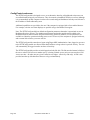
One Final Word on the Overview
From the overview descriptions so far on Rockhound, it should be clear that Rockhound is a very flexible
collection of firmware modules that can be combined in a number of ways to provide a great deal of
flexibility.
The Rockhound architecture is very scalable, allowing more channels and more elaborate processing to be
done, limited only by the available computing resources.
New Rockhound modules are expected to be added to the list of modules described in this manual. For
specific applications, it is possible that existing modules can be combined in ways not considered, or that
new modules are being designed now that do what is needed. It is also possible that a custom module could
be quickly designed that would meet the exact criteria. Contact Kinemetrics for further information.
6/20/2011
Document 304702 Rev N
Page 17
2. ROCKTal
R
lk
This chap
pter covers thee program RO
OCKTalk thatt provides thee primary userr interface to Rockhound ffor setup and
parameterr editing.
ROCKT
Talk Overview
As
A seen from the
t example descriptions
d
giiven in the ovverview, the cconfiguration of Rockhounnd is done with
h
teext files, and communicatio
c
on with Rock
khound can bee done primarrily through sstandard interffaces such as
Telnet
T
and SCP
P/FTP.
However,
H
it sh
hould also be clear
c
by now that the numbber of availabble Rockhounnd modules annd the numbeer
off configuratio
on options maake manual co
onfiguration aan intimidatinng prospect foor anyone withh better things
to
o do than to leearn all of thee detailed intriicacies of Rocckhound interrnals.
For this reason
n, Kinemetrics developed a program callled ROCKTaalk.
ROCKTalk
R
is designed to walk
w that fine line betweenn hiding the coomplexities oof dealing withh Rockhound
d
an
nd limiting acccess to the po
ower of that complexity.
c
Inn other wordss, ROCKTalkk tries to provvide the best of
o
bo
oth worlds.
ROCKTalk
R
is written in Jav
va like the resst of the Rockkhound softwaare. This meaans that ROCK
KTalk can bee
ru
un on any com
mputing platfo
orm that supp
ports Java - suuch as the variious Window
ws Operating S
Systems, Sun's
Solaris, and Liinux. It also means
m
that alth
hough a unit m
may be runniing on Linux,, the user can communicatee
with
w it effectiv
vely from a deesktop compu
uter running W
Windows.
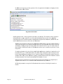
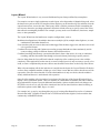
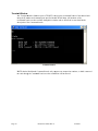
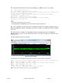
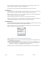
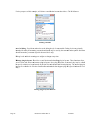
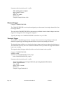
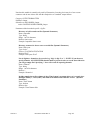
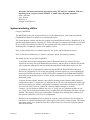
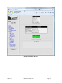
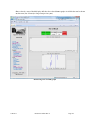
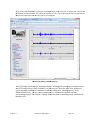
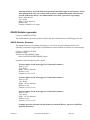
ROCKTalk Displaay
Looking
L
at thee display, notee the followin
ng major compponents of thhe ROCKTalkk display:
- Title bar show
ws the name of
o the program
m (KMI ROC
CKTalk) and tthe currently selected unit
- Menu for acccess to functio
ons of ROCK
KTalk
- Tool bar butttons for fast access
a
to the most
m commonnly used functtions of ROC
CKTalk
- Scrollable tex
xt area to disp
play status
- Status line at the bottom of
o the display
6/20/2011
Document 304702 Rev N
Page 19
Notice that the title bar includes standard window functions supported by the Operating System. This
display example was taken under Windows, so it includes Minimize, Maximize, and Exit buttons.
What can ROCKTalk do?
ROCKTalk has a wide variety of capabilities, most of which will be described in detail further in this
section. However, here's a quick overview:
- Controls multiple units
- Remembers connection addresses
- Interfaces with remote Rockhound via SCP/FTP or a network file sharing LAN
- Layout wizard for creation of Rockhound layouts from standardized templates
- Rockhound parameter editor
- Retrieval and sending of Rockhound parameters
- Archival of Rockhound configurations for later use
- Module replacement
- Terminal window access to units
- Waveform viewer window
- Validation of Rockhound layout to make sure it is correct
- Management of Rockhound registration codes
- Firmware update of units
- Advanced functions:
- Module delete
- Module insert
- Debug level control (Special advanced level only)
- Manage plug-in layouts (Special advanced level only)
- Module rename (Special advanced level only)
- Subscription editing (Special advanced level only)
Page 20
Document 304702 Rev N
6/20/2011
Menu
The ROCKTalk menu includes the following functions. Most of these functions are described further in the
tool bar section, with the exception of those few infrequently used functions that are available only through
the menu. These menu only functions are described here.
FILE
Open Layout - Opens a Rockhound layout, usually for editing. Layouts can be read from a unit.
Save Layout - Save a Rockhound layout. Layouts can be saved to a unit.
Archive Layout (Special advanced level only) - Archive a layout by placing all files of the layout into a
JAR file for later reference.
De-archive Layout (Special advanced level only) - De-archive a layout by extracting files from a
specified JAR file. De-archived layout information may be extracted with or without hardware
specifics of an individual unit.
Exit - Exits from ROCKTalk.
SETUP
Layout Wizard - Creates Rockhound layouts from a list of standardized templates. Pick the basic way
Rockhound should be used, and the wizard asks the questions needed to complete the layout.
Terminal Window - Opens a terminal window (via TELNET) to the selected unit.
Waveform Viewer Window - Opens a waveform viewer window that connects to the selected unit's
Telemetry Connection module, if one is included in the Rockhound layout. See the description of the
Waveform Viewer tool bar button, and the description of the Telemetry Connection Rockhound
module.
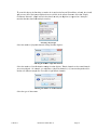
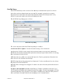
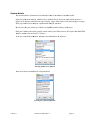
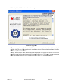
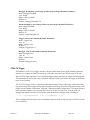
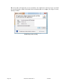
Get Registration Info - Gets registration info from the selected unit. This function gets registration
information that is used to authorize use of the main Rockhound firmware as well as additional
chargeable options for Rockhound.
When this function is selected, a file dialog will appear that is to be used to determine where the
registration information is to be stored. The registration information is stored as a .CFG file.
Kinemetrics recommends that registration information be uploaded and archived by the customer
so that this information is available as a backup. Be sure to assign a unique and meaningful name
to the registration data file.
This information is useful when registering new hardware, when assigning additional registration
codes to Rockhound to enable additional chargeable features as well as if it should become
necessary to determine the authorization status of a unit.
NOTE: Registration is not required for Rockhound when used on a Rock digitizer such as a
Granite.
6/20/2011
Document 304702 Rev N
Page 21
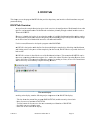
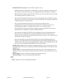
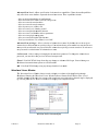
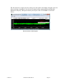
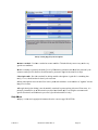
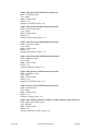
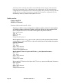
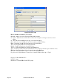
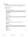
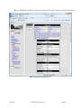
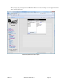
In add
dition to the creation
c
of thee registration file, the regisstration inform
mation is dispplayed in the
centerr window of ROCKTalk:
R
Registra
ation informattion
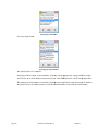
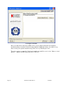
Send Regiistration Info - Sends regisstration info too the selectedd unit. This fuunction sends registration
informatio
on that is used
d to authorizee use of the m
main Rockhounnd firmware aas well as addditional
chargeablee options for Rockhound. After
A
sendingg updated regiistration inforrmation, ROC
CKTalk will
instruct Ro
ockhound to restart
r
to utiliize the new reegistration.
Witho
out valid registration codess access to Roockhound funnctionality is sseverely limitted. Without a
valid registration code
c
for the main
m Rockhouund firmware,, the Rockhouund firmwaree will start butt
will display
d
warnin
ng messages on
o startup andd will run in ddemo mode ffor up to 12 hoours and will
then terminate.
t
In this
t demo mo
ode, all Rockhhound modules may be useed but only foor the 12 hourr
trial period.
p
If a vaalid registratiion code existts for the mainn Rockhoundd firmware, thhen there is obbviously no 12
2
hour limit.
l
However, if addition
nal modules aare added to thhe configurattion that are nnot part of the
basic Rockhound firmware
f
pack
kage (but are separately auuthorized chaargeable optioons) then those
ules WILL NO
OT START. Modules
M
requuiring separatee authorizatioon will be marrked as such in
n
modu
the do
ocumentation
n. Check the documentation
d
n (this manuaal) to be sure.
n registration information is
i supplied byy Kinemetricss for Rockhouund, it will geenerally be
When
suppllied in the form
m of a .CFG file that can bbe transmittedd directly to thhe unit.
NOTE
E: Registratio
on is not required for Rockkhound when used on a Roock digitizer ssuch as a
Graniite.
Page 22
Document 304702 Rev N
6/20/2011
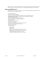
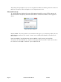
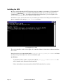
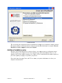
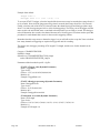
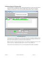
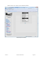
Rockhound Firmware Update - Sends a firmware update to a unit.
Rockhound firmware is distributed as a JAR file that is a single file containing a collection of files.
This is similar to a ZIP file in many ways. See Definitions for more information on JAR files.
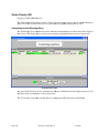
When the Firmware Update menu selection is made, the user will be requested to select the JAR
file containing the firmware update to be sent.
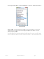
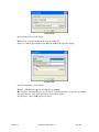
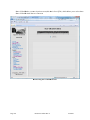
After selecting the firmware image, the user will be presented with a list of available units. This
allows the user to update one or more units at one time. ROCKTalk will manage the transmission
of updated firmware to all selected units.
Once selected, ROCKTalk will connect to the selected units by talking to their
CommandConsole(s) and will determine where the firmware is located on the unit. Every
Rockhound layout includes a CommandConsole module - See Command Console.
Next, ROCKTalk will transfer the firmware update to the unit using SCP/FTP or file copy as
determined by the configuration of each unit within ROCKTalk.
After transfer of the update, ROCKTalk will command the unit to restart. Restarting the unit
allows it to extract, install and execute the update. Validation of the new firmware is done
automatically by the unit before accepting and installing the new firmware. The validation process
can take up to a minute to complete.
Please note that unlike previous Kinemetrics products, the design of Rockhound allows new
firmware to be loaded without having to default parameters and reconfigure Rockhound like you
would do with an Altus recorder after updating firmware. Kinemetrics recommends however, that
the user still review the Rockhound parameters after a firmware update.
Edit Hardware Config - Edits the hardware configuration parameters of the selected unit. These are
the parameters that are unique to a particular unit such as the Rockhound name, serial number, sensor
information, etc.
Edit Parameters - Edits the Rockhound parameters of the selected unit. These parameters are not
unique to a particular unit, and these parameters should be useable by a group of units that are set up
similarly.
Replace Module - Replace a module with another compatible module type.
Advanced Features - Access to advanced ROCKTalk features.
HELP
About - ROCKTalk version and copyright information.
6/20/2011
Document 304702 Rev N
Page 23
Tool Bar
B
The
T tool bar prrovides fast acccess to ROCKTalk functioons without hhaving to naviigate through a menu. Mosst
fu
unctions availlable on the to
ool bar are alsso available oon the menu th
though, so forr most activitiies, use of thee
menu
m
or use off the tool bar is a matter off personal preeference.
This
T section deescribes ROC
CKTalk functiions in detail,, with only a ffew functionss that are not aavailable
th
hrough the too
ol bar describ
bed in the Men
nu section.
Notice
N
that too
ol bar and diallog buttons co
ontain tool tipps. So if the ccursor is placeed over a buttton or other
diisplay widgett and held there for about two
t seconds, a tool tip thatt briefly descrribes the funcction of the
diisplay elemen
nt will appearr:
ROCK
KTalk Tool Tiips
Open La
ayout
This
T operation
n opens a Rock
khound layou
ut by reading it from a seleected unit.
Rockhound
R
lay
youts consist of multiple fiiles, as describbed earlier inn this manual. The Open Laayout function
n
reeads all of theese files into ROCKTalk
R
so
o that they maay be revieweed, changed, oor saved.
When
W
Open Laayout is seleccted, the user is
i presented w
with a selectioon dialog as ffollows:
Open Layout Dialoog
Page 24
Document 304702 Rev N
6/20/2011
Reads
R
the layo
out from the cu
urrently seleccted unit. Thiss is done by R
ROCKTalk auutomatically pperforming the
fo
ollowing steps:
- Connect to th
he selected un
nit's Command
dConsole to ddetermine wheere the layoutt is located onn the unit. (See
Command
dConsole)
- Transfer the layout
l
using SCP/FTP
S
or file
f copy as seelected for thiis unit.
- Place the retrrieved layout into the layou
ut configuratiion directory and expand itt into the variious files that
comprise the
t layout.
Iff the layout vaalidates, ROC
CKTalk will display
d
the vaalidation messsage.
Save La
ayout
This
T operation
n saves a Rock
khound layou
ut by sending it to a selecteed unit.
Rockhound
R
lay
youts consist of multiple fiiles, as describbed earlier inn this manual. The Save Laayout function
n
writes
w
all of theese files from
m ROCKTalk so
s that they m
may be stored for future usee or transmitteed to a unit fo
or
im
mmediate use.
When
W
Save Laayout is selectted, the user is
i presented w
with a selectioon dialog as fo
follows:
Save Layout Dialogg
S
the layout to the currrently selecteed unit. This iis done by RO
OCKTalk autoomatically
Send to unit - Sends
peerforming thee following stteps:
- Write the currrent layout/co
onfiguration that
t ROCKTaalk has open iinto a temporrary JAR file called
"config.jarr".
- Connect to th
he selected un
nit CommandC
Console to deetermine wheere the layout is located on the unit.
- Transfer the layout
l
using SCP/FTP
S
or file
f copy as seelected for thiis unit.
- Instruct the unit
u (via the CommandCon
C
nsole) to termiinate the currrent Rockhounnd layout andd JVM and
restart so that
t the new layout
l
and/or configurationn activates.
6/20/2011
Document 304702 Rev N
Page 25
Layout Wizard
The Layout Wizard makes it easy to create Rockhound layouts from predefined layout templates.
For example, to create a simple continuous recorder layout, select the number of channels being used, select
the data source (such as an RS-232 interfaced Altus digitizer or an IP interfaced Q330), and then select the
output format of how to store the data. That's pretty much it. Edit the parameters before transmitting the
new layout to the unit to set/change parameters from their default values or to specify some of the values
that cannot be meaningfully defaulted. For example, you may need to set IP addresses, baud rates, sample
rates, or other parameters.
The Layout Wizard can also handle more complex configurations, such as:
Rockhound configurations with multiple data sources (multiple Q330s, multiple Altus digitizers, or some
combination of dissimilar datasources).
Event recorders with one or more data sources that trigger filter the data, trigger on it, and then event record
it in a specified format.
Combined Event recording and Continuous recording systems that both store data continuously and do
event recording, perhaps in different formats, and on different drives.
Combined recording and telemetry systems that take data in from a data source, do event or continuous
recording, and then forward the data through a selected telemetry link using a specific protocol.
One nice thing about the Layout Wizard is that the complexity of the creation process scales with the
complexity of the application. In other words, to create a simple layout it is only necessary to specify a few
items; to create a complicated layout more choices must be made because there are obviously more choices.
When a layout template calls for the inclusion of a module into the layout, the Layout Wizard will check to
see how many compatible modules of that type exist. If there is more than one choice then the user will be
requested to select the desired module. If on the other hand there is only one choice, then the module is
silently added and the user is not bothered with a question.
Once all of the modules of the layout have been selected, the final step of the Layout Wizard will be to
display a list of predefined options. These are modules (or combinations of modules) that can be added to
the completed basic layout to provide additional functionality. Options would include such things as an
HTTP Server (web server), auto file delete, timed activities such as timed checkin or timed recording, or
notification options such as SMS, Pager, or e-mail.
For example, let's go step by step through the process of creating a Rockhound Layout for a Continuous
Recorder that takes 3 channels of data in from a TCP/IP interfaced Altus digitizer, and records the data
continuously in MiniSEED format.
Page 26
Document 304702 Rev N
6/20/2011
To
T create this layout,
l
the firrst thing we neeed to do is too select the Laayout Wizardd. Once selectted, the wizard
d
will
w present a list
l of the layo
out templatess that are avai lable in the cuurrent firmwaare. Select thee "Simple
Continuous
C
Reecorder", simp
ple in that it takes
t
data from
m only one ddigitizer (as oppposed to a "ccomplex"
reecorder that taakes data from
m multiple reccorders:
Selecting a layout tyype
mber of physiccal channels coming
c
from tthe digitizer:
Select the num
Sellecting the num
mber of physiical channels
mber of virtuall channels com
ming from thhe digitizer. V
Virtual channeels are the actuual channels
Select the num
ou want produced - for exaample, you might
m
have 4 pphysical channnels (1-4), buut want data pproduced for
yo
eaach at two diffferent samplee rates for a to
otal of eight vvirtual channeels:
Seelecting the nu
umber of virtu
ual channels
Select the typee of data sourcce:
6/20/2011
Document 304702 Rev N
Page 27
urce
Selecting the data sou
Select the outp
put format:
Selecting the output foormat
The
T initial layo
out is now com
mplete.
Using
U
the paraameter editor, set the param
meters of the nnew layout apppropriately. In this particuular example
yo
ou will have to
t set the IP address
a
and po
ort used by thhe "Altus SDS
S Input thru T
TCP/IP" and pperhaps otherss.
The
T meaning of
o each param
meter is describ
bed in the help
lp string at thee bottom of thhe edit window
w. In addition
n,
deescriptions arre given in thee description of each Rockkhound modulle, located latter on in this m
manual.
Page 28
Document 304702 Rev N
6/20/2011
After
A
making all
a the needed
d edits to the Rockhound
R
pparameters, thhe parameter llist for this coonfiguration
sh
hould look so
omething like this:
Parameters after setup coomplete
6/20/2011
Document 304702 Rev N
Page 29
Termina
al Window
w
The
T Terminal Window
W
funcction opens a TELNET sesssion to the C
CommandConnsole of the seelected unit
ussing the IP ad
ddress and com
mmand port specified
s
in R
ROCKTalk Seetup. All funcctions of the
CommandCon
C
nsole are then available thro
ough this winndow and are described in some detail inn the
deescription of the Command
dConsole.
Term
minal Window
w
NOTE
N
that thee Rockhound CommandCo
onsole only suupports one coonnection at a time, so whhile connected
d
to
o a unit throug
gh its CommaandConsole no
n other conneection will bee allowed.
Page 30
Document 304702 Rev N
6/20/2011
RockTa
alk Setup
Enters
E
ROCKT
Talk Setup to allow selectiion of unit andd setup of com
mmunicationns options for each unit.
s
of th
he advanced user
u passwordd. This passw
word is primarrily there to reestrict
Itt also allows selection
in
nexperienced users from so
ome of the mo
ore complex ffunctions. Noo advanced usser password is set by
deefault. If a paassword is neeeded, select Set Password aand specify oone.
The
T ROCKTallk Setup dialo
og appears as follows:
ROCKT
Talk Setup Diaalog
The
T various co
omponents off the ROCKTaalk Setup diallog are as folllows:
unit Selection and List Up
pdates - Proviides the meanns to manage a list of know
wn unit.
A pull down list ("ROCK1"" in this exam
mple) allows seelection betw
ween several ppreviously deffined unit.
ROCKTalk
R
wiill remember communicatio
c
ons options foor each unit, ssaving the useer the trouble of re-entering
g
th
hese each timee a new unit is
i selected.
ADD
A
allows th
he user to deffine a new uniit and add it too the list. Thee first questioon that will bee asked is the
naame of the neew unit. This name
n
must bee unique.
DELETE
D
allow
ws deletion off a unit from the
t list of knoown unit. To delete a unit ffrom the list, select it from
m
th
he pull down list and selectt DELETE.
RENAME
R
allo
ows renaming
g of an existing
g unit. To renname a unit, seelect it from tthe pull downn list and selecct
RENAME.
R
IP
P Address an
nd Command
d Port of uniit - ROCKTallk uses TCP/IIP to communnicate with a uunit. Use of
TCP/IP
T
requirees an IP addreess and a Com
mmandConsolle IP Port num
mber. The most important ppart of TCP/IP
P
co
ommunication
n with the uniit is the ability
y to connect too the CommaandConsole off the unit. Theese parameters
alllow specificaation of the un
nit IP addresss and commannd port. (See CommandCoonsole)
6/20/2011
Document 304702 Rev N
Page 31
IP ADDRESS (127.0.0.1 in this example) specifies the IP address of the selected unit. Each unit will be
assigned a unique IP address by whoever sets up your network, just as each computer on a LAN is assigned
a unique IP address. In this example, 127.0.0.1 is used, an IP addressing convention that indicates that the
selected unit is running on the same computer as ROCKTalk.
CONTROL PORT (9900 in this example) specifies the CommandConsole port for the unit. 9900 is the
default for the CommandConsole module.
CONSOLE PASSWORD must be set to the same value as the unit command console password parameter.
Unless changed here and in the unit layout, both the unit and ROCKTalk will use the same default
password. See the detailed description of the CommandConsole module.
NOTE: All Rockhound layouts must include a CommandConsole.
SCP/FTP Login name and password of unit - If file communication between ROCKTalk and the unit
will be done via SCP/FTP, then an SCP/FTP login name and SCP/FTP password must be specified. If file
copy will be used instead of SCP/FTP (as in this example), then the SCP/FTP login name and SCP/FTP
password will be disabled.
LOGIN NAME Specifies the login name used for SCP/FTP login.
SCP/FTP PASSWORD specifies the SCP/FTP password expected by the unit.
File Path to unit - If file communication between ROCKTalk and the unit will be done via file copies, then
a file path to the unit must be specified. The path can be specified by typing it in directly, or by using the
Browse Path button to navigate to the unit directory.
If this method is used, the File Path must be directly accessible from the ROCKTalk computer. In other
words, it should be possible to use the copy and directory functions of the operating system to access the
directory and the files in that directory without needing to use SCP/FTP or other such methods. Local hard
drives are certainly supported, but "shared" or "network mounted" drives can also be used in this way.
The selected directory should be the one that contains the subdirectories bin, classes, config, injar, lib and
outjar.
FTP used for file transfers - This is where the choice is made to use FTP or file copies for file
communication between ROCKTalk and this unit. The option is set independently for each unit.
SCP used for file transfers - This is where the choice is made to use SCP or file copies for file
communication between ROCKTalk and this unit. The option is set independently for each unit.
Page 32
Document 304702 Rev N
6/20/2011
Advanced
A
Useer Level - Alllows specification of advaanced user cappabilities. Theese advancedd capabilities
on
nly affect tho
ose users that have
h
requesteed advanced uuser status. Thhese capabilitties include:
- Allow archiv
ving/dearchiviing of configu
urations
- Allow choicee of SCP/FTP
P or COPY forr config accesss
- Allow accesss to advanced modules
- Allow accesss to advanced parameters
- Allow layoutt save to or fro
om a file
- Allow accesss to Level of Debug
D
contro
ol
- Allow accesss to Module Rename
R
functiion
- Allow accesss to Test Mod
dules and test parameters
- Allow accesss to plugin maanagement
- Allow accesss to Subscriptiion Edit functtion
- View layout each time it is validated, even if OK
Advanced
A
Useer privileges - Allows seleection of advaanced user staatus. By defauult, the user iss not given
ad
dvanced user status and haas no special privileges.
p
If aan advanced uuser passwordd has been sett, then the useer
must
m provide the advanced user password before advaanced user priivileges can bbe turned on. No advanced
d
usser password is needed to turn
t
off advan
nced user stattus.
Set Password - Allows settting or changiing the advannced user passsword. To chaange the advaanced user
paassword, you must know th
he previous advanced
a
userr password.
Cancel
C
- Exitss ROCKTalk Setup discard
ding any channges to Advannced Privilegees. Unsaved cchanges to
Rockhound
R
communication
ns options are also discardeed.
OK
O - Exits RO
OCKTalk Setu
up saving any
y changes thatt have been m
made.
Wavefo
orm Viewerr Window
The
T Waveform
m Viewer Win
ndow button is
i used to dispplay waveform
ms of the dataa flowing throough
Rockhound.
R
Prressing the Waveform
W
Viewer Window
w button will ccause ROCKT
Talk to show a list of
av
vailable chann
nels on the un
nit. One or mo
ore of the wavveforms representing these channels mayy be displayed
d
by
y selecting fro
om the list. Each
E
waveform
m will be dispplayed in a seeparate windoow.
Waveform Viiewer Selectioon display
6/20/2011
Document 304702 Rev N
Page 33
The
T componen
nts of the Wav
veform Vieweer Selection ddisplay, or "R
ROCK Vision" are as follow
ws:
Ho
ost - The IP
I address of
o the unit
Po
ort - The Telemetry
T
Co
onnection port of the unit
Di
isconnect - Press to disconnect,
d
press agai
in to reconn
nect to this unit or a
another unit
t
? - Help on this versio
on of Rock Vision
Ch
hannels Ava
ailable - Ch
hannels reported by th
he unit as a
available f
for telemetr
ry
Ro
ockhound Id
d - Rockhoun
nd ID string
Me
essage box - Telemetry
y related status messa
ages
Vi
iew Channel
l - Press to
o display waveform win
ndows of sel
lected chan
nnels
Co
onnected - Rock Vision
n status
Notes:
N
- The Rock Vision window may be resized
- Closing the Rock
R
Vision window
w
closes all waveforrm windows ccreated by it.
The
T viewer is intended
i
as a quick check of the overalll condition off the unit, andd not as a dataa collection orr
daata processing
g facility. How
wever, within
n those restricctions, it can ggive a good geeneral feel forr the condition
n
off the unit.
The
T Waveform
m Viewer requ
uires a corresp
ponding Teleemetry Conneection object tto be includedd in the
Rockhound
R
lay
yout. If none is present, theen the Wavefform Viewer ddialog will staart, but will inndicate a portt
nu
umber of zero
o.
The
T Waveform
m Viewer appears as follow
ws:
Waveforrm Viewer dissplay
The
T functions across the too
ol bar portion
n of the Wave form Viewer window are aas follows:
UN
NITS - Shor
rt here in counts.
c
Incl
ludes count
ts, Volts, G
G, gal, cm/s^2, and cu
ustom units.
.
RE
ESET - Clea
ars the disp
play and sample counte
er.
PA
AUSE - Paus
ses the disp
play, but does not aff
fect data fl
lowing thro
ough Rockhou
und.
RE
ESUME - Res
sumes displa
ay of data after a pau
use.
WI
IDTH – Widt
th of the wi
indow in seconds.
Y LIMIT – Se
ets the Y ax
xis display limit if n
not auto-sca
aled.
UTOSCALE - Autoscales the data to fit the d
display.
AU
ME
EAN - Remov
ves the mean
n from the displayed d
data.
Page 34
Document 304702 Rev N
6/20/2011
The
T Waveform
m Viewer may
y be paused by clicking in the data portiion of the dispplay. Doing tthis pauses thee
diisplay and sho
ows instantan
neous values such
s
as the saample numberr, amplitude oof the markedd sample,
in
nstantaneous frequency,
f
an
nd segment ab
bsolute peak-tto-peak valuee. Click RESU
UME to continue the
diisplay.
Waveform Viewer
V
clicked to pause
6/20/2011
Document 304702 Rev N
Page 35
Edit Harrdware Co
onfiguration
n
The
T Rockhoun
nd configuratiion data is log
gically divideed into two sections: That w
which is hardw
ware specificc,
an
nd that which
h is not.
This
T function allows
a
editing
g of those parrameters that aare hardware specific. Posssible hardwarre specific
paarameters cou
uld include in
ndividual unit serial numbeers or sensor iinformation.
Upon
U
selecting
g Edit Hardwaare Configuraation, a standaardized edit ddialog will appear that willl contain as
many
m
hardware related paraameters as aree appropriate to the currentt configuratioon.
Hardw
ware Edit Diallog
Note
N the brief description of each parameter to the lefft of the valuee, that some vvalues are readd-only (like
maximum
m
num
mber of chann
nels), and also
o note the exteended descripption for the ccurrent param
meter at the
bo
ottom of the dialog.
d
On
O exit from th
he dialog, parrameters are range
r
checkedd to make suree that they aree of the propeer type and are
within
w
their deefined limits.
Page 36
Document 304702 Rev N
6/20/2011
This
T example is
i from the Co
ontinuous Recording exam
mple built in tthe Layout W
Wizard section..
Edit Parrameters
The
T Rockhoun
nd configuratiion data is log
gically divideed into two sections: That w
which is hardw
ware specificc,
an
nd that which
h is not.
This
T function allows
a
editing
g of those parrameters that aare NOT harddware specific. Upon seleccting Edit
Parameters, a standardized
s
edit
e dialog wiill appear that will contain aas many param
meters as are appropriate to
o
th
he current con
nfiguration.
Param
meter Edit Diallog
Note
N the brief description off each parameeter to the left
ft of the value,, the fact that some values are read-only
y,
an
nd also note the
t extended description
d
fo
or the current parameter at the bottom oof the dialog. A
Also note the
sccroll bar to th
he right of the dialog becau
use it is very llikely that theere will be moore parameterrs in the
co
onfiguration than
t
can fit on
n one screen.
6/20/2011
Document 304702 Rev N
Page 37
On
O exit from th
he dialog, parrameters are range
r
checkedd to make surre that parameeters entered are of the
prroper type and are within the
t limits declared for eachh parameter.
This
T example is
i from the Co
ontinuous Recording exam
mple built in tthe Layout W
Wizard section..
Archive
e Layout
This
T function allows
a
the currrent Rockhou
und layout annd configuration to be storeed as a single JAR file. This
alllows the layo
out to be storeed for future use
u as a singlee file. (Speciaal advanced level only)
When
W
the funcction is selecteed, a file selection dialog w
will be presennted that is ussed to select thhe name and
lo
ocation of a JA
AR file to holld the presentt configuratioon.
NOTE
N
that reg
gistration info
ormation is no
ot affected by Archive and De-Archive functions.
Naming
N
is left totally up to the
t user, so a name
n
should bbe selected thhat indicates w
what unit this information is
frrom, and perh
haps additionaal information
n about what type of layouut is containedd in it.
De-Arch
hive Layou
ut
This
T function allows
a
openin
ng of an archiv
ve JAR file soo that a configguration may bbe restored too a unit or used
d
ass a basis for configuration
c
of another un
nit. (Special aadvanced leveel only)
When
W
the funcction is selecteed, a file selection dialog w
will be presennted that is ussed to select thhe name and
lo
ocation of a JA
AR file to be opened and de-archived.
d
De-Arch
hive type selecction
After
A
selecting
g the file, the user
u must select between ttwo de-archivve options:
Full
F unit specific restore - Restores all aspects
a
of thee layout and cconfiguration,, including haardware and
non-hardw
ware specific components.
Model
M
restoree based on an
nother unit - Restores onlyy those parts of the layout configurationn that are not
hardware specific - thatt is to say eveerything exceppt hardware.ccfg. This allow
ws the inform
mation to be
used as the basis for thee layout and configuration
c
n of another siimilar unit.
NOTE
N
that in either
e
case, reegistration infformation is nnot affected bby Archive annd De-Archivee functions.
Page 38
Document 304702 Rev N
6/20/2011
Replace
e Module
This
T function allows
a
replaceement of Rocckhound moduules with anoother compatibble module.
Using
U
the replaacement funcction, moduless can be replaaced after the layout has beeen initially ccreated. A
trrigger can be replaced
r
with
h a different ty
ype of trigger,, trigger filterrs replaced wiith different tyypes of triggeer
fiilters, input daata sources ch
hanged, outpu
ut formats chaanged, and soo on.
In
n each case, th
he user's choiices are limiteed to compatib
ible modules dduring a replaacement.
Using
U
the Conttinuous Recorder examplee created in thhe Layout Wizzard section, llet's replace thhe MiniSEED
D
Archiver
A
modu
ule with an Altus EVT Arcchiver.
To
T do this, seleect Replace Module,
M
and th
hen select thee module to bbe replaced:
Selecting module
m
to be reeplaced
Then
T
select thee new modulee that is being
g substituted:
Selecting thee replacementt module
6/20/2011
Document 304702 Rev N
Page 39
After
A
making the
t replacemeent, be sure to review the paarameters to m
make sure thatt any parametters of the new
w
module
m
are sett properly beffore sending th
he revised coonfiguration too the unit.
Advanc
ced Feature
es
The
T Advanced
d Features fun
nction allows more detailedd operations w
which are more difficult cooncepts and
which
w
should not
n be attemp
pted by other than
t
advancedd users. The aadvanced feattures selection appears as
fo
ollows:
Advanced
d Features seleection
In
nsert a modu
ule - Providess a method to insert modulees into the layyout. As withh deleting moddules, this can
n
qu
uickly becom
me complicated. For examp
ple, in many ccases moduless publish dataa that is subsccribed to by
otther modules..
Iff you insert module
m
C into the data streaam between m
modules A and B you may need to edit tthe
su
ubscriptions such
s
that mod
dule B now su
ubscribes to thhe output of thhe new moduule C and the nnew module C
no
ow subscribes to the outpu
ut of module A.
A It gets com
mplicated fastt.
Page 40
Document 304702 Rev N
6/20/2011
For the purposes of this exaample, we'll in
nsert a modulle that has no subscribers - We'll insert a Web Serverr:
Inserrting a modulee
Delete
D
a modu
ule - Providess a method to delete modulles out of the layout. Althoough this seem
ms simple
en
nough, it can become comp
plicated if thee module beinng deleted puublishes data w
which is then in turn
su
ubscribed to by
b other modu
ules.
Iff you delete module
m
B of a data stream consisting
c
of modules A, B
B, and C you may need to first change
module
m
C so th
hat it now sub
bscribes to mo
odule A and tthen delete moodule B. Agaain, it gets com
mplicated fastt.
6/20/2011
Document 304702 Rev N
Page 41
For the purposses of this exaample, we'll delete
d
a modulle that has noo subscribers - The Web Seerver:
Deleting a modulee
Level
L
of debug - Provides a method to set the debug llevels of eachh module. Deebug levels aree primarily
in
ntended for usse by Kinemettrics personneel and should only be used by the custom
mer under speecific direction
n
frrom Kinemetrrics personnell. (Special advanced level only)
Debug
D
levels and
a their mean
nings are subjject to changee at any time..
Manage
M
plug--in layouts - Provides
P
a sett of functionss for handlingg plug-in layoouts. These funnctions allow
w
yo
ou to create, edit,
e
delete an
nd rename plu
ug-in layouts. Once plug-inn layouts are ccreated, they may be edited
d
to
o specify activ
vities to be peerformed on the data for eaach channel (tthe actual pluug-ins). The ccreated plug-in
n
laayouts are avaailable for selection from Rockhound
R
m
modules that suupport plug-inns. (Special aadvanced leveel
on
nly)
Manage plug
g-in layouts fu
unctions
Page 42
Document 304702 Rev N
6/20/2011
Neewly created plug-in
p
layout description
Rename
R
a mo
odule - Provid
des a method to rename moodules. This sshould only bbe necessary uunder very
sp
pecial test con
nditions.
Module
M
renam
ming is primarily intended for
f use by Kinnemetrics perrsonnel and shhould only bee used by the
cu
ustomer undeer specific direection from Kinemetrics
K
ppersonnel. (Sppecial advanceed level only))
Subscription edit
e - Providees a method for
f editing moodule subscripptions. Againn this is sometthing that
raarely, if ever, should need to
t be done by
y the customeer.
Editing
E
subscriiptions alters the data flow
w in the system
m and could leeave some moodules as "orpphans" that no
o
lo
onger receive data.
Although
A
subscription editin
ng is not subsstantially resttricted beyondd requiring A
Advanced Userr status, it is
prrimarily inten
nded for use by
b Kinemetriccs personnel aand should onnly be used byy the customeer under
sp
pecific directiion from Kineemetrics personnel. (Speciial advanced llevel only)
Help Ab
bout
Displays
D
versio
on and copyriight informatiion about the current copyy of ROCKTaalk.
6/20/2011
Document 304702 Rev N
Page 43
3. How Do I...
This chapter addresses commonly asked questions about the configuration and operation of the Rockhound
firmware and/or the ROCKTalk software.
The main goal here is to deal with common questions and operational issues.
Add a unit to ROCKTalk
To add a unit to ROCKTalk so that it is remembered in the list of available units, select the Open Layout or
Save Layout function, and then go to ROCKTalk Setup.
Once in ROCKTalk Setup, click the Add button at the top of the dialog and enter the name of the new unit
when asked. The name is only for display purposes within ROCKTalk and can be any reasonable length.
Press OK after entering the name.
Enter additional information needed to communicate with the unit including its IP address and file transfer
method (SCP/FTP or file copies) and any other needed details.
If communication with the unit will be via SCP/FTP, then specify:
- IP address of unit
- Command port of unit (default is 9900)
- Select the checkbox for "FTP used for file transfers" or "SCP used for file transfers"
- SCP/FTP login name
- SCP/FTP password
- Press ROCKTalk Setup's OK button to save the changes
If communication with the unit will be using file transfers, then specify:
- IP address of unit
- Command port of unit (default if 9900)
- Uncheck the checkboxes for "FTP used for file transfers" and "SCP used for file transfers"
- File path to the unit SMARTSDist directory
- Press ROCKTalk Setup's OK button to save the changes
6/20/2011
Document 304702 Rev N
Page 45
Select a unit
To select which instrument ROCKTalk communicates with, select the Open Layout or Save Layout
function, and then go to ROCKTalk Setup.
Once in ROCKTalk Setup, pull down on the list of units at the upper left hand corner of the dialog and
select a unit. If the unit needed is not yet in the list, follow the directions as described in "Add a unit". Press
OK after entering the name.
After exiting ROCKTalk Setup, the name of the unit will be displayed on the title bar of the ROCKTalk
window.
Make a New Configuration
To discard the current configuration of the unit and create a new layout and configuration, make sure to
select the unit to be affected first.
Next, select the Layout Wizard from the menu or the tool bar. The Layout Wizard is described in another
section of this manual.
After using the Layout Wizard to create the layout, edit the unit parameters to set up the parameters in detail
as required. To do this, select Edit Parameters from the menu or tool bar and set the parameters as needed.
Once the Layout has been created and the parameters properly adjusted to meet the requirements, send the
updated configuration to the unit by selecting Save Layout from the menu or tool bar and then press Send to
unit.
The layout can also be saved to a file or the layout can be archived for future use.
Edit Rockhound Parameters
To edit parameters of an existing Rockhound configuration, select the unit to be affected first.
Next, load the configuration from the unit (or from a file) by selecting Open Layout from the menu or tool
bar and then selecting From a File or From a unit as appropriate.
Once the configuration is loaded into ROCKTalk, select Edit Parameters from the menu or tool bar and edit
the parameters as needed.
To change modules - for example to change an event recorder to use STA/LTA triggering instead of
threshold triggering, or to use an IIR trigger filter rather than a Classic Strong Motion trigger filter, use the
Replace Module function rather than the Edit Parameters function. Edit Parameters is intended for altering
parameters within currently included modules. After changing the layout by replacing, inserting, or deleting
modules it is a good idea to review the parameters using Edit Parameters.
After editing the parameters, select Save Layout from the menu or toolbar and then choose Send to unit or
Save to File as needed.
Archive a Rockhound Layout
After creating a new layout or making significant changes to Rockhound parameters, it is a good idea to
archive a copy of the parameters for future reference or backup.
Page 46
Document 304702 Rev N
6/20/2011
With the layout currently loaded into ROCKTalk, select Archive Layout from the menu or tool bar. Specify
the location and name of the JAR file into which the layout will be saved. Be sure to use a filename that will
be meaningful in identifying the unit and/or type of layout.
De-archive a Rockhound Layout
To restore a previously archived Rockhound layout, make sure to select the unit to be affected first if the
layout will be sent to a unit after de-archiving it.
Select De-Archive Layout from the menu or tool bar. Specify the name of the JAR file that is being
de-archived using the file selection dialog.
After giving the filename, choose whether to do a "Full Unit Specific Restore", which extracts all of the
layout including those items that are specific to an individual unit (hardware.cfg), or select "Model Restore
Based on Another Unit", which extracts everything except the parameters unique to an individual unit
(everything except hardware.cfg). This second method allows using a layout for multiple units where
similar setup is desired.
After extracting the layout, review and/or correct the parameters using Edit Parameters and finally send the
parameters to the unit by selecting Save Layout and then Send to unit.
Open a Terminal Window
To open a terminal window to the unit, make sure to select the unit to be affected first.
Next, select the Terminal Window function from the menu or tool bar. This function will open a TELNET
session (a terminal window) using the IP address and command port as listed for the unit on the ROCKTalk
Setup dialog.
Update Rockhound Firmware
To update Rockhound Firmware, first locate the firmware update file. This will be a JAR file and will be
named in the form UpdateXXXX.jar. Make sure to select the unit to be updated first.
Select Rockhound Firmware Update from the menu and select the update file. The file will be sent to the
unit using the connection specified in ROCKTalk Setup for that unit and then Rockhound will be
commanded to restart.
When Rockhound restarts, it will see the update firmware file and will unpack it and install it, and then will
restart again to make use of the new firmware.
After updating firmware be sure to review the unit parameters.
6/20/2011
Document 304702 Rev N
Page 47
Access the Linux Console
To access the Linux console on a Linux based system, connect an RS-232 connection to the RS-232 console
port (/dev/console). This port is enabled at 9600 baud, 8-N-1.
In some cases, it may be necessary to initially log into Linux via the console before the network has been
configured, and before access via Telnet is possible.
Manage Plug-in Files
The files that contain attributes of plug-ins, including those used for data filtering, are contained in what are
called Plug-in Files. These files have a ".plg" extension. Some plug-in files are supplied by Kinemetrics
with the Rockhound Distribution, and will be automatically placed in the config/plugins directory when the
Rockhound distribution is installed either on the unit itself, or in the config/pluginarchive directory on the
PC used to run ROCKTalk.
When a configuration is sent to a unit, the contents of the config/pluginarchive directory will be included in
the config.jar file that is sent to the unit. These files will be unpacked into the config/plugins directory on
the unit. The user may define his own plug-in files subject to the definition of the structure of plug-in files,
and may include these files in the config/pluginarchive directory on the PC used to run ROCKTalk. These
additional files will be sent to the unit when configuration information is sent, and these user defined files
will not be overwritten on the PC by a Rockhound software update or other configuration change.
Please note that the plug-in files stored on the PC will be included in the configuration information for every
unit that is accessed and controlled by ROCKTalk on that PC.
The details of the contents of a Plug-in File are dependent on the type of plug-in, and will be described in
the detailed description of the plug-in, which includes plug-in filters.
Manage Plug-in Layout Files
Plug-in layout files define data processing activities to be performed for a particular unit. Plug-in layouts
must be created for each unit, and each plug-in layout's data must be edited to specify the data processing
activities (the actual plug-ins used) for each channel of the plug-in layout.
Plug-in layout files are located in config/pluginlo, and are included in any configuration data uploaded or
downloaded from each unit.
Page 48
Document 304702 Rev N
6/20/2011
4. Software Installation
This chapter addresses installation of ROCKTalk software, as well as use of the Rockhound firmware on a customer
supplied computer.
Descriptions are given of the installation process, which varies from the highly automated methods that Kinemetrics
expects to be most commonly used, through less commonly used applications requiring more manual intervention
during or after installation.
Overview
Rockhound firmware and support software are written in Java. As one result of this, the distribution has
been reduced to a single CD. This CD can be can be used to install Rockhound support software on multiple
platforms, such as Windows operating systems, Sun workstations, Linux, and more.
Kinemetrics will include in the installation only those platforms that have been tested, even if it is possible
that the software might work on another platform.
The following are included on the CD:
- Rockhound firmware, as an UPDATExx.JAR file.
- ROCKTalk support software.
- Installation routines for supported platforms.
- JVMs for supported platforms.
- Support libraries for supported platforms.
- This manual as a PDF file.
This section describes the process of installing the Rockhound software from CD. The installation process
uses Zero G's InstallAnywhere software, which is a multi-platform installer. So although the installation
examples you'll see here are for a Windows computer, they are essentially the same as what you'd see on a
Linux machine or Sun workstation.
6/20/2011
Document 304702 Rev N
Page 49
Installiing the JV
VM
In
n order to run
n Rockhound or
o ROCKTalk
k software onn your compuuter, you mustt have a JVM installed. If
yo
ou know for sure
s
that you have a compaatible JVM innstalled on yoour system, yoou can skip too the step
"A
Additional Installation Nottes". This secction will tell yyou how to ddetermine if you are using tthe correct
veersion of the JVM
J
and if not,
n how to insstall the correect version.
On
O Windows, Linux, and Unix
U
the fastesst way to findd out what verrsion of the JV
VM you havee installed is to
o
op
pen a commaand window and
a type "javaa -version"" as follows:
Checking
g the Java verrsion
The
T version sh
hould be versiion 1.4.0 or hiigher. If it is nnot then folloow the instrucctions on how
w to install thee
neew version.
Itt may be neceessary to use a command su
uch as "/usr//java/jre1.4.0_01/bin java -versiion" on Linux
x
orr Solaris if the java directo
ories have nott been added tto the path.
For
F Windows:
To install the JVM for windows, loccate and run thhe file j2re-11_4_0_01-wiindows-i586--i.exe that
will be inccluded on the Kinemetrics Rockhound C
CD.
Follow thee installation instructions and
a install thee JVM. Recheeck the Java vversion.
Page 50
Document 304702 Rev N
6/20/2011
For Linux:
Locate the file j2re-1_4_0_01-linux-i586.bin that will be included on the Kinemetrics Rockhound
CD. This is the Linux JVM installation. Place the file in a directory /usr/java that you may have to
create. Make the file executable and run it, by using the following command from the directory in
which it is now located:
./j2re-1_4_0_01-linux-i586.bin
The script will display a binary license agreement, which you will be asked to agree to before
installation can proceed. Once you have agreed to the license, the install script will install the JVM in a
directory named jdk1.4.0_01 in the current directory.
For Solaris:
Locate the file j2re-1_4_0_01-solaris-sparc.sh that will be included on the Kinemetrics
Rockhound CD. This is the Linux JVM installation. Place the file in a directory /usr/java that you
may have to create. Make the file executable and run it, by using the following command from the
directory in which it is now located:
./j2re-1_4_0_01-solaris-sparc.sh
The script will display a binary license agreement, which you will be asked to agree to before
installation can proceed. Once you have agreed to the license, the install script will install the JVM in a
directory named jdk1.4.0_01 in the current directory.
Create a "jar" file in the /usr/java/jre1.4.0_01/bin directory (or equivalent). It should be
executable for all users and contain the following one line:
java sun.tools.jar.Main $*
Reboot or log out and recheck the Java version.
Installing for Solaris
Installation on a Sun workstation is mostly the same as described for Linux or Windows, but the CD format
common to many Solaris systems is somewhat incompatible with the formats created by the tools used by
Kinemetrics.
It is recommended that you transfer these files to your workstation via FTP or another similar method, and
then directly execute the install.bin file located in the subdirectory InstData/Unix/Solaris.
Be sure that you have appropriate permissions to install the software.
Once you are able to begin the installation, skip to the step "Installation Steps".
6/20/2011
Document 304702 Rev N
Page 51
Installiing for Windows
W
or
o Linux
After
A
inserting
g the CD, locaate the file IN
NSTALL.HTM
M - this is the file that is thhe starting poiint for the
In
nstallAnywheere installer. Open
O
this file with your broowser, whichh on most Winndows machinnes is done by
y
siimply double--clicking on the
t file icon. On
O Linux youu single-clickk.
NOTE:
N
On som
me systems itt may be neceessary to downnload the insttall to your haard drive, andd follow the
siimple installattion instructio
ons given on the
t INSTALL
L.HTM screenn. You may seee a security nnotice warning
g
yo
ou that the installer is abou
ut to install so
ome software on your systeem temporariily. The installler is not
co
onnecting to the
t internet, itt does not posse a security rrisk.
On
O Linux, be sure
s
that you have
h
approprriate permissioons to install the software..
The
T next screeen you'll see iss the first actu
ual install screeen:
IN
NSTALL.HTM
M file open in tthe browser.
Page 52
Document 304702 Rev N
6/20/2011
Note
N that in thiis example the screen inclu
udes a one cli ck button (in this case, "Sttart Installer ffor Windows")
to
o start the insttaller for yourr particular pllatform. This shows the plaatform that thhe installer deetected. The
otther availablee installers forr other platforrms are listedd below. (If yoour display dooesn't show thhe one click
bu
utton, then seelect from thatt list of availaable installerss below.)
Download" iss little mislead
ding, as the download is reeally from thee CD to your hard drive.
"D
Installa
ation Steps
Once
O
the installlation gets sttarted in detaiil, you may seee a screen suuch as the folllowing to indiicate that the
in
nstaller is unp
packing the so
oftware and getting it readyy for installattion:
Insta
all preparation
n
Next,
N
you'll bee allowed to select the locaale (or languagge) for the insstallation. Thhis is a standarrd
In
nstallAnywheere feature, an
nd will changee the standarddized messagees of the instaaller.
Installl locale selectioon
6/20/2011
Document 304702 Rev N
Page 53
After
A
selecting
g the locale, seeveral screens will displayy to step throuugh the installlation processs. First is the
sccreen indicating that the in
nstaller is read
dy to begin:
Installl ready to beg in
Page 54
Document 304702 Rev N
6/20/2011
Following this is the Kinem
metrics softwaare license agrreement:
Install liicense agreem
ment
The
T next screen
n selects the installation
i
fo
older. Kinemeetrics recomm
mends that the software be iinstalled in the
deefault folder. The rest of th
he examples in
i the installaation section w
will assume thhat the softwaare is installed
d
in
nto D:\Progra
am Files\SM
MARTS.
NOTE:
N
That on Windows Vista,
V
Rockho
ound cannot bbe installed innto Program F
Files because of restrictions
th
hat Windows Vista
V
places on
o programs in
i the Program
m Files directoory. For Winddows Vista, w
we recommend
d
th
hat you installl Rockhound off of the roo
ot directory innto a folder likke \Rockhounnd\SMARTS..
6/20/2011
Document 304702 Rev N
Page 55
Choosing
g the install foolder
Now
N you will be
b asked to seelect the JVM
M that will be used to run thhe Rockhounnd code. Kinem
metrics
reecommends th
hat you selectt the JVM thaat is shipped w
with the Rockkhound software. If you doon't see any
ch
hoices at this point, quit th
he installation and go back to the step "IInstalling the JVM".
Iff you know yo
ou have a com
mpatible JVM
M already instaalled and wouuld like to usee it, select "Chhoose a virtuaal
machine..."
m
and
d then make the
t appropriatte choice. Cliick Next.
Page 56
Document 304702 Rev N
6/20/2011
Cho
oose the JVM
The
T screens that follow may
y indicate thatt the installatiion has changged your envirronment variaables, and thaat
th
he computer will
w have to bee rebooted forr the changes rrequired by thhe installationn to be compleete. When the
in
nstallation is totally comp
pleted, reboo
ot your comp
puter.
Additio
onal Insta
allation notes
n
In
n order to run
n Rockhound firmware
f
or support
s
softw
ware, your com
mputer must bbe configuredd to support
TCP/IP.
T
Settin
ng up your com
mputer for IP
P is not withinn the scope off this documenntation. However, you
sh
hould be able to "ping" ano
other computeer or use Telnnet or FTP to communicatee with anotheer computer to
o
prrove this capaability is prop
perly set up beefore you prooceed.
Iff you don't kn
now what ping
g, Telnet, and
d FTP are, conntact your sysstem administtrator or referr to your
co
omputer's doccumentation.
6/20/2011
Document 304702 Rev N
Page 57
Running ROCKTalk
The installation process will have created icons or shortcuts on your system to ROCKTalk. ROCKTalk is
the program that is used to communicate with one or more units from your computer. On most systems, no
further installation should be necessary.
Note: On some versions of Windows, such as the Japanese version of Windows 98 - it may be necessary to
manually create your own shortcut to the file ROCKTalk.exe.
See the section of this manual that describes ROCKTalk.
Running Rockhound on your computer
Running Rockhound on your computer (allowing your computer to act as a unit and thus directly control
your digitizers) requires some additional steps. You DO NOT need to perform these steps if you only plan
to run ROCKTalk.
For Windows:
If running Windows 98, or ME, you'll need to locate the file winrun.bat and make a copy of it (in the
same directory) called winrerun.bat. After doing this, right click on the file icon and set the amount
of environment memory to as large as possible, and select the "close on exit" option. Select APPLY
and OK. Repeat this for both files. This should only be necessary at the first install.
For Windows NT through Windows Vista, no additional setup is required to enable these batch files.
To run Rockhound, run the batch file winrun.bat.
For Linux:
If you plan to have your unit communicate with the digitizer via an RS-232 connection, then perform
the following additional steps:
Make the serial ports /dev/ttyS0 and /dev/ttyS1 read/write for all users. Note that these
serial ports are specifically enabled for use in unixrun.sh this prevents the serial library from
trying to access all possible ports in the world - taking longer to start AND generating lots of
unneeded messages.
Reboot your computer.
To run Rockhound, run the script file "sh unixrun.sh".
Page 58
Document 304702 Rev N
6/20/2011
For Solaris:
Kinemetrics does not supply the necessary support libraries and instructions to support RS-232
interface to a digitizer. Most Sun workstations have few if any serial ports, and Kinemetrics believes
that most digitizers controlled by Sun workstations will be interfaced via an IP connection.
If you feel you need to use Kinemetrics' Rockhound to control digitizers via RS-232 from a Sun
workstation, contact Kinemetrics for further assistance.
To run Rockhound, run the script file "sh unixrun.sh".
Once Rockhound is running, you will probably see a message at startup of the batch or script file that
indicates that the Authorization code is missing, such as:
HWId: 00b0b9f246a2
Warning: Missing or invalid registration.
Demo Mode: Rockhound will halt in 12 hours!
This message means that authorization to use the Rockhound software must be obtained from Kinemetrics
in order to use your computer as a unit. See the section on "Get Registration Information" in the ROCKTalk
section of this manual, or contact Kinemetrics for further information.
On computers using the Windows Operating System, you may see a message such as:
HWId: JHWId ERROR
This most likely means that your computer is not set up with the NetBIOS service enabled. This service is
required in order to get the hardware identification information from your computer necessary to run the
Rockhound software.
6/20/2011
Document 304702 Rev N
Page 59
5. Rockhound Modules
This section describes each Rockhound module in terms of its behavior, possible subscriptions, and parameters.
In the following examples, some parameter names or values are created using other values defined by Rockhound.
These include:
'digitizer' = The name of the related digitizer
'digchannels' = The number of channels for this digitizer
'nchannels' = The total number of channels affected by this Rockhound configuration
'chan' = The current channel number
'plug-ins list' = The list of defined data plug-ins
'plug-in layouts list' = The list of user defined plug-in layouts
Available categories and modules
Each Rockhound module belongs to a category of similar modules. For example, there might be several
different types of trigger filters available, but they all share one common feature - namely that they are all
trigger filters. In other cases, such as the Voter, there might only be one choice.
When selections are made based on module category, the software will determine how many modules there
are of that category. If there is only one module of that category, the software will choose that module
without further user input. One the other hand, if there are several choices possible, then the software will
ask the user to choose which module should be used.
Current categories and modules supported are:
Multichannel source for data
- Altus SDS Input from TCP/IP
- Altus SDS Input from RS232
- Q330 Input from UDP/IP
- Rock Data Interface
- MZD24 Data Interface
- TSASMA Data Interface
- Ring Buffer Data Interface
- Pseudo Data Waveform Generator (Advanced)
Data multichannel integrator
- Data Integrator
Status integrator
- Status Integrator
Channel extractor
- Channel Extractor
6/20/2011
Document 304702 Rev N
Page 61
Channel trigger filter
- Classic Strong Motion Filter
- IIR-A Filter
- IIR-C Filter
- LPSRO Filter (Advanced)
- LPWWSS Filter (Advanced)
- GS21 Filter (Advanced)
- SPWWSS Filter (Advanced)
Channel trigger
- Threshold Trigger
- STA/LTA Trigger
Channel data filter
- DIY FIR Filter (Advanced)
- DIY IIR Filter (Advanced)
- Velocity IIR Filter (Advanced)
- Displacement IIR Filter (Advanced)
- Post-Integration IIR Filter (Advanced)
Voter
- Voter
- CGS Voter
Event recorder
- Recorder
Continuous recorder
- Continuous Recorder
File data formatter and archiver
- MiniSeed Format Data Archiver
- SAC Format Data Archiver
- COSMOS Format Data Archiver
- MATLAB Format Data Archiver
- SEISAN Format Data Archiver
- Altus EVT Format Data Archiver
- Text Format Data Archiver
- SUDS Format Data Archiver
- SEISLOG Format Data Archiver
Link to external data source
- NMS Queue Monitor
Auto File sender
- FTP File Sender
- SCP File Sender
- E-Mail File Sender
Command console
- Command console
System monitoring utilities
- Update monitor
Status Display GUI
- Status Display GUI (Desktop Only)
- PGA Alarms Display GUI (Desktop Only)
Status serving utilities
- Status Server
Page 62
Document 304702 Rev N
6/20/2011
Auto file delete scanner
- Aged Auto File Delete
- Auto Oldest File Delete
- Auto Small EVT File Delete
Statistics generator
- Run Time Parameter Statistics
- Summary File Generator
- JMA Summary File Generator
- SOH File Generator
Web Server
- Config/Control web server
Telemetry connections
- Waveform viewer
Data Relay to transmit data stream
- DFS Telemetry (Advanced)
- SVDR Telemetry (Advanced)
- Altus Telemetry via RS-232
- Altus Telemetry via TCP/IP
- CGS Altus Telemetry via RS-232
- CGS Altus Telemetry via TCP/IP
- PPP Dial Generation
- QSCD Packet Telemetry
Local mirror of a data source
- SEEDLink Stream Mirrored to Disk
Ring Buffer Server
- Ring Buffer Server
Timed event alarm clock
- Alarm Clock
User notifier
- E-Mail Message Sender
- SMS Message Sender
- File Forwarder
Interconnect facilities
- Network Trigger
General Purpose IO interface
- Rock GPIO
- Rock PGA GPIO
OASIS Display GUI
- OASIS Display GUI (Desktop Only) (Advanced)
OASIS Data bridge
- OASIS Data Bridge (Advanced)
Mathematical integration of data (A-->V-->D)
- OASIS Mathematical Integrator (Advanced)
Computes drift between specified displacement channels
- OASIS Drift Computer (Advanced)
OASIS Statistics generator
- OASIS Statistics Generator
OASIS drift trigger
- OASIS Drift trigger (Advanced)
OASIS Alarm controller
- OASIS Alarm controller module (Advanced)
6/20/2011
Document 304702 Rev N
Page 63
Channel pre-extractor
- Channel Pre-Extractor
Data processing plug-ins
- Data Plug-in Layout
Configuration information common to all Rockhound layouts
A few parameters are defined for every Rockhound system. These parameters are added to the smarts.cfg
and/or hardware.cfg configuration files. Parameters added to smarts.cfg:
Data directory that will be scanned for available space by the Status Monitor
Name: DataDir
Type: String
Range: 1 to 100 characters
Default: \data
Example: DataDir=\data
If used, data directory used instead of the standard system temporary directory. The temporary
data directory is used for working files such as the raw data recorded before it is converted to
the final data output format. This could be used for example to relocate the temporary directory
to an available SD card. If set to NONE, the standard system temporary directory is used.
(Advanced)
Name: TempDataDir
Type: String
Range: 1 to 100 characters
Default: NONE
Example: TempDataDir=NONE
Spare space required on the file system in order to record new files (in KB). If remaining space is
below this number, the system will not create new event files. (KMI only)
Name: DataCushion
Type: int
Range: 0 to 4000000
Default: 10000
Example: DataCushion=10000
Maximum size of log files in bytes (KMI only)
Name: MaxLogBytes
Type: int
Range: 1 to 409600000
Default: 102400
Example: MaxLogBytes=102400
Parameters added to hardware.cfg:
Unit identification string
Name: SMARTSId
Type: String
Range: 1 to 20 characters
Default: KMI
Example: SMARTSId=KMI
Page 64
Document 304702 Rev N
6/20/2011
Network identification string
Name: NetworkId
Type: String
Range: 1 to 20 characters
Default: KM
Example: NetworkId=KM
Site identification string
Name: SiteId
Type: String
Range: 0 to 20 characters
Default: none
Example: SiteId=string
User defined comment string
Name: Comment
Type: String
Range: 0 to 64 characters
Default: none
Example: Comment=string
Number of channels total in this system
Name: NChannels
Type: int
Range: 1 to 99
Default: 'nchannels'
Example: NChannels='nchannels'
Multichannel source for data
Category: CHANNELDATASOURCE
The CHANNELDATASOURCE is normally the first module in a Rockhound data flow, and provides the
interface to each of the digitizers which are attached to Rockhound.
It provides control of the communications link, communications protocols, configuration options, data
retrieval, and Rockhound initiated control of a digitizer. Rockhound may have several
CHANNELDATASOURCE modules providing data, limited by the available processing time.
Altus SDS Input from TCP/IP
Module name: AltusTCPFrontEnd
This module serves as the Rockhound interface to a Kinemetrics Altus recorder that is serving as a digitizer
and is connected via a TCP/IP socket connection.
If Rockhound is connected to more than one Altus digitizer, then more than one FrontEnd module (either an
AltusTCPFrontEnd or an AltusRS232FrontEnd) should be included in the Rockhound configuration
layout.
6/20/2011
Document 304702 Rev N
Page 65
The FrontEnd module does not subscribe to any other modules, but communicates with the Altus digitizer
in Kinemetrics Serial Data Streams (SDS) mode.
On startup, the FrontEnd requests the current status of the Altus digitizer, and checks the various Altus
parameters against the FrontEnd parameters to make sure they match. Parameters would include, but are
not limited to sampling rate, SDS enabled, SDS buffer size, SDS compression mode, and selected channels.
If the Altus and FrontEnd parameters do not match, then the FrontEnd module will modify the Altus
parameters and send them back to the Altus, and acquisition and SDS may or may not be restarted as
needed.
Once the parameters of the Altus and FrontEnd match, several of the parameters are stored in the run time
parameters of Rockhound so that they can be used by other modules (for example, for inclusion in recorded
files). At this point, SDS data will be accepted from the digitizer and passed into the Rockhound system for
further processing by the rest of the modules.
If the configuration of the Altus has not been changed, the FrontEnd will attempt to recover data missing
since the last Rockhound shutdown. Missing data will not be recovered if the Altus SDS configuration has
changed. The amount of data recovered depends on several things:
- The Size of the Altus SDS buffer
- The Retry Seconds parameter in hardware configuration
- The Recovery Limit parameter in the module configuration
- The amount of data actually in the SDS buffer
The default parameter settings will recover data as needed for up to 1800 seconds (30 minutes). "As
Needed" is specified as the Recovery Limit parameter, and the 1800 seconds is specified as the Retry
Seconds parameter.
NOTE 1: In order to use very long recovery limits (Retry Seconds set to more than 1800), you must make
sure that there is sufficient SDS storage on the digitizer and that available bandwidth allows current data
plus recovered data for extended periods of time - otherwise the missing data may never be recovered or
will take an unacceptably long time. For large recovery limits, Altus firmware v2.99 or higher is
recommended.
NOTE 2: Altus firmware v2.89 and below only support 100sps streaming data. Firmware versions 2.90 and
later will support any of the sampling rates supported by the Rockhound Altus front end modules.
NOTE 3: Make sure that the Altus does not contain an internal modem, as this will interfere with Altus
block mode communications needed for proper interface with Rockhound.
Category: CHANNELDATASOURCE
Publishes: Output
Subscribes to: NOTHING
Page 66
Document 304702 Rev N
6/20/2011
Parameters added to hardware.cfg:
User settable name of the digitizer
Name: 'digitizer'.Name
Type: String
Range: 1 to 80 characters
Default: 'digitizer'
Example: 'digitizer'.Name='digitizer'
Host address of the incoming data socket
Name: 'digitizer'.Host
Type: String
Range: 0 to 80 characters
Default: none
Example: 'digitizer'.Host=string
TCP Port number for incoming data, should be greater than 2000
Name: 'digitizer'.TCPPort
Type: int
Range: 2000 to 32767
Default: none
Example: 'digitizer'.TCPPort=2000
Channel ID string for the channel
Name: 'digitizer'.ch'chan'.Id
Type: String
Range: 1 to 80 characters
Default: C'chan'
Example: 'digitizer'.ch'chan'.Id=C'chan'
Sensitivity value for the channel in volts per unit, e.g. volts per g - needed for
EVT,SUDS,SEISAN and COSMOS files
Name: 'digitizer'.ch'chan'.Sensitivity
Type: double
Range: 0.001 to 10000.0
Default: 1.25
Example: 'digitizer'.ch'chan'.Sensitivity=1.25
Full scale range value for the channel in +/- volts - needed for EVT,SUDS and COSMOS files
Name: 'digitizer'.ch'chan'.FullScale
Type: double
Range: 0.001 to 10000.0
Default: 2.5
Example: 'digitizer'.ch'chan'.FullScale=2.5
6/20/2011
Document 304702 Rev N
Page 67
Sensor Type index for the channel (10=FBA-11, 11=FBA-4g, 12=FBA-2g, 13=FBA-1g,
14=FBA-0.5g, 15=FBA-0.25g, 16=FBA-0.1g, 20=FBA-23, 30=WR-1, 32=EpiSensor, 33=S6000,
34=Mark L22, 35=Mark L4C, 36=CMG, 37=CMG3T, 38=CMG40T, 39=CMG5, 40=KS-2000,
41=GT-S13, 42=CMG3ESP, 43=KMI-SH1, 44=KMI-SV1) - needed for EVT, SAC and
COSMOS files
Name: 'digitizer'.ch'chan'.SensorType
Type: int
Range: 0 to 9999
Default: 32
Example: 'digitizer'.ch'chan'.SensorType=32
Sensor serial number for the channel
Name: 'digitizer'.ch'chan'.SensorSN
Type: int
Range: 0 to 99999
Default: 0
Example: 'digitizer'.ch'chan'.SensorSN=0
Sensor natural frequency for the channel, in Hz
Name: 'digitizer'.ch'chan'.NaturalFreq
Type: double
Range: 0 to 9999
Default: 200
Example: 'digitizer'.ch'chan'.NaturalFreq=200
Sensor damping for the channel (between 0 and 1)
Name: 'digitizer'.ch'chan'.Damping
Type: double
Range: 0 to 1
Default: 0.7
Example: 'digitizer'.ch'chan'.Damping=0.7
Gain value for the channel - needed for EVT,SUDS,SEISAN and COSMOS files
Name: 'digitizer'.ch'chan'.Gain
Type: int
Range: 1 to 5000
Default: 1
Example: 'digitizer'.ch'chan'.Gain=1
EpiSensor gain value, should be set to match the sensor's jumper settings (1=2.5V range, 2=5.0V,
4=10V, 8=20V)
Name: 'digitizer'.ch'chan'.EpiGain
Type: choice
Choices: 1,2,4,8
Default: 2
Example: 'digitizer'.ch'chan'.EpiGain=2
Page 68
Document 304702 Rev N
6/20/2011
EpiSensor range code, where 1=4g, 2=2g, ... 5=0.25g - should be set to match the sensor's jumper
settings
Name: 'digitizer'.ch'chan'.EpiRange
Type: choice
Choices: 1,2,3,4,5
Default: 1
Example: 'digitizer'.ch'chan'.EpiRange=1
EpiSensor Cal Coil value in g/V. This is a factory calibrated value
Name: 'digitizer'.ch'chan'.EpiCalCoil
Type: double
Range: 0.05 to 0.10
Default: 0.05
Example: 'digitizer'.ch'chan'.EpiCalCoil=0.05
Altitude value for the channel in degrees - needed for EVT,SAC and COSMOS files
Name: 'digitizer'.ch'chan'.Altitude
Type: int
Range: -90 to 90
Default: 0
Example: 'digitizer'.ch'chan'.Altitude=0
Azimuth value for the channel in degrees - needed for EVT,SAC,SUDS and COSMOS files
Name: 'digitizer'.ch'chan'.Azimuth
Type: int
Range: 0 to 360
Default: 0
Example: 'digitizer'.ch'chan'.Azimuth=0
Channel offset north value for the channel in meters
Name: 'digitizer'.ch'chan'.OffsetNorth
Type: double
Range: -32000 to 32000
Default: 0
Example: 'digitizer'.ch'chan'.OffsetNorth=0
Channel offset east value for the channel in meters
Name: 'digitizer'.ch'chan'.OffsetEast
Type: double
Range: -32000 to 32000
Default: 0
Example: 'digitizer'.ch'chan'.OffsetEast=0
Channel offset up value for the channel in meters
Name: 'digitizer'.ch'chan'.OffsetUp
Type: double
Range: -32000 to 32000
Default: 0
Example: 'digitizer'.ch'chan'.OffsetUp=0
6/20/2011
Document 304702 Rev N
Page 69
Location code string for the channel - needed for EVT, MiniSEED files and/or Ring Buffer
storage
Name: 'digitizer'.ch'chan'.LocationCode
Type: String
Range: 0 to 80 characters
Default: none
Example: 'digitizer'.ch'chan'.LocationCode=string
Network code string for the channel - needed for EVT, SAC, MiniSEED files and/or Ring Buffer
storage. Defaults to the global Network ID if not specified.
Name: 'digitizer'.ch'chan'.NetworkCode
Type: String
Range: 0 to 80 characters
Default: none
Example: 'digitizer'.ch'chan'.NetworkCode=string
Station code string for the channel - needed for EVT, SAC, MiniSEED files and/or Ring Buffer
storage. Defaults to the global Station ID if not specified.
Name: 'digitizer'.ch'chan'.StationCode
Type: String
Range: 0 to 80 characters
Default: none
Example: 'digitizer'.ch'chan'.StationCode=string
Calib value for the channel - needed for Ring Buffer storage
Name: 'digitizer'.ch'chan'.Calib
Type: double
Range: -1000000 to 1000000
Default: 0.0
Example: 'digitizer'.ch'chan'.Calib=0.0
Calper value for the channel - needed for Ring Buffer storage
Name: 'digitizer'.ch'chan'.Calper
Type: double
Range: -9999 to 9999
Default: -1.0
Example: 'digitizer'.ch'chan'.Calper=-1.0
SegType for the channel - needed for Ring Buffer storage
Name: 'digitizer'.ch'chan'.SegType
Type: String
Range: 0 to 80 characters
Default: Example: 'digitizer'.ch'chan'.SegType=Number of ADC counts at +/- full scale, in counts
Name: 'digitizer'.ch'chan'.FullScaleADCCounts
Type: int
Range: 1 to 100000000
Default: 8388608
Example: 'digitizer'.ch'chan'.FullScaleADCCounts=8388608
Page 70
Document 304702 Rev N
6/20/2011
Maximum retry request buffer time, in seconds. See Recovery Limit in the front end
configuration.
Name: RetrySeconds
Type: int
Range: 1 to 1209600
Default: 1800
Example: RetrySeconds=1800
Maximum current data recovery buffer, in packets. Limits how much current data can be
queued as recovery progresses. Should be made smaller on systems with many digitizers and
small memory.
Name: RecoveryQueueLimit
Type: int
Range: 1 to 1209600
Default: 3000
Example: RecoveryQueueLimit=3000
Parameters added to module specific .cfg file:
Sampling rate, in SPS [NOTES: 1) Etna supports 100,200,250sps only. 2) Values other than
100sps allowed in Altus App version 2.96 or higher only!]
Name: SPS
Type: choice
Choices: 20,40,50,100,200,250
Default: 100
Example: SPS=100
Number of channels produced by this digitizer
Name: NDigitizerChannels
Type: int
Range: 1 to 6
Default: 'digchannels'
Example: NDigitizerChannels='digchannels'
List of channels to be sent, e.g.: 1,2,3. NOTE: Number of selected channels MUST be less or
equal to the number of channels to be produced by this digitizer.
Name: Channels
Type: String
Range: 1 to 80 characters
Default: 1,2,3
Example: Channels=1,2,3
Record temperature stream as .deg
Name: Temperature
Type: boolean
Default: true
Example: Temperature=true
6/20/2011
Document 304702 Rev N
Page 71
Record VofV12Batt stream as .vvb
Name: VofV12Batt
Type: boolean
Default: false
Example: VofV12Batt=false
Record time quality stream as .lcq
Name: TimeQual
Type: boolean
Default: true
Example: TimeQual=true
Difference compression of the data stream
Name: Compress
Type: boolean
Default: true
Example: Compress=true
Buffer size of Altus ring buffer in 16kb blocks
Name: Buffer
Type: int
Range: 0 to 65535
Default: 64
Example: Buffer=64
Maximum amount of data to recover from the real-time stream when unit restarts. See Retry
Seconds in hardware configuration
Name: Recover
Type: choice
Choices: As Needed,None,10 min,20 min,30 min,1 hr,2 hr,4 hr,8 hr
Default: None
Example: Recover=None
This digitizer is optional. If selected and initial connection to the digitizer fails, then the unit will
continue to operate without it. If not optional, a successful connection is required or the unit will
restart.
Name: OptionalDigitizer
Type: boolean
Default: false
Example: OptionalDigitizer=false
Page 72
Document 304702 Rev N
6/20/2011
Drum recorder special simplex communication mode. This is intended only for specialized use
with drum recorder output. In this mode, Rockhound will only listen to the Altus and will not
send any data. Any control of the Altus will be done by someone else (such as an upstream
Earthworm, Antelope, or NMS client). In particular, recovery is the responsibility of the
upstream host, though a short timeout for the DataIntegrator is recommended (10-15 seconds)
to keep data flowing in the case of an opccasional non-recovered packet loss. SOH channels will
not be published. This module's parameters should be set up to match those of the Altus for
channel count, sample rate, and other parameters. (Advanced)
Name: DrumMode
Type: boolean
Default: false
Example: DrumMode=false
Altus SDS Input from RS232
Module name: AltusRS232FrontEnd
Same as an AltusTCPFrontEnd, except that the recorder is connected via an RS-232 connection rather than
via a TCP/IP socket connection.
Category: CHANNELDATASOURCE
Publishes: Output
Subscribes to: NOTHING
Parameters added to hardware.cfg:
User settable name of the digitizer
Name: 'digitizer'.Name
Type: String
Range: 1 to 80 characters
Default: 'digitizer'
Example: 'digitizer'.Name='digitizer'
Channel ID string for the channel
Name: 'digitizer'.ch'chan'.Id
Type: String
Range: 1 to 80 characters
Default: C'chan'
Example: 'digitizer'.ch'chan'.Id=C'chan'
Sensitivity value for the channel in volts per unit, e.g. volts per g - needed for
EVT,SUDS,SEISAN and COSMOS files
Name: 'digitizer'.ch'chan'.Sensitivity
Type: double
Range: 0.001 to 10000.0
Default: 1.25
Example: 'digitizer'.ch'chan'.Sensitivity=1.25
6/20/2011
Document 304702 Rev N
Page 73
Full scale range value for the channel in +/- volts - needed for EVT,SUDS and COSMOS files
Name: 'digitizer'.ch'chan'.FullScale
Type: double
Range: 0.001 to 10000.0
Default: 2.5
Example: 'digitizer'.ch'chan'.FullScale=2.5
Sensor Type index for the channel (10=FBA-11, 11=FBA-4g, 12=FBA-2g, 13=FBA-1g,
14=FBA-0.5g, 15=FBA-0.25g, 16=FBA-0.1g, 20=FBA-23, 30=WR-1, 32=EpiSensor, 33=S6000,
34=Mark L22, 35=Mark L4C, 36=CMG, 37=CMG3T, 38=CMG40T, 39=CMG5, 40=KS-2000,
41=GT-S13, 42=CMG3ESP, 43=KMI-SH1, 44=KMI-SV1) - needed for EVT, SAC and
COSMOS files
Name: 'digitizer'.ch'chan'.SensorType
Type: int
Range: 0 to 9999
Default: 32
Example: 'digitizer'.ch'chan'.SensorType=32
Sensor serial number for the channel
Name: 'digitizer'.ch'chan'.SensorSN
Type: int
Range: 0 to 99999
Default: 0
Example: 'digitizer'.ch'chan'.SensorSN=0
Sensor natural frequency for the channel, in Hz
Name: 'digitizer'.ch'chan'.NaturalFreq
Type: double
Range: 0 to 9999
Default: 200
Example: 'digitizer'.ch'chan'.NaturalFreq=200
Sensor damping for the channel (between 0 and 1)
Name: 'digitizer'.ch'chan'.Damping
Type: double
Range: 0 to 1
Default: 0.7
Example: 'digitizer'.ch'chan'.Damping=0.7
Gain value for the channel - needed for EVT,SUDS,SEISAN and COSMOS files
Name: 'digitizer'.ch'chan'.Gain
Type: int
Range: 1 to 5000
Default: 1
Example: 'digitizer'.ch'chan'.Gain=1
Page 74
Document 304702 Rev N
6/20/2011
EpiSensor gain value, should be set to match the sensor's jumper settings (1=2.5V range, 2=5.0V,
4=10V, 8=20V)
Name: 'digitizer'.ch'chan'.EpiGain
Type: choice
Choices: 1,2,4,8
Default: 2
Example: 'digitizer'.ch'chan'.EpiGain=2
EpiSensor range code, where 1=4g, 2=2g, ... 5=0.25g - should be set to match the sensor's jumper
settings
Name: 'digitizer'.ch'chan'.EpiRange
Type: choice
Choices: 1,2,3,4,5
Default: 1
Example: 'digitizer'.ch'chan'.EpiRange=1
EpiSensor Cal Coil value in g/V. This is a factory calibrated value
Name: 'digitizer'.ch'chan'.EpiCalCoil
Type: double
Range: 0.05 to 0.10
Default: 0.05
Example: 'digitizer'.ch'chan'.EpiCalCoil=0.05
Altitude value for the channel in degrees - needed for EVT,SAC and COSMOS files
Name: 'digitizer'.ch'chan'.Altitude
Type: int
Range: -90 to 90
Default: 0
Example: 'digitizer'.ch'chan'.Altitude=0
Azimuth value for the channel in degrees - needed for EVT,SAC,SUDS and COSMOS files
Name: 'digitizer'.ch'chan'.Azimuth
Type: int
Range: 0 to 360
Default: 0
Example: 'digitizer'.ch'chan'.Azimuth=0
Channel offset north value for the channel in meters
Name: 'digitizer'.ch'chan'.OffsetNorth
Type: double
Range: -32000 to 32000
Default: 0
Example: 'digitizer'.ch'chan'.OffsetNorth=0
Channel offset east value for the channel in meters
Name: 'digitizer'.ch'chan'.OffsetEast
Type: double
Range: -32000 to 32000
Default: 0
Example: 'digitizer'.ch'chan'.OffsetEast=0
6/20/2011
Document 304702 Rev N
Page 75
Channel offset up value for the channel in meters
Name: 'digitizer'.ch'chan'.OffsetUp
Type: double
Range: -32000 to 32000
Default: 0
Example: 'digitizer'.ch'chan'.OffsetUp=0
Location code string for the channel - needed for EVT, MiniSEED files and/or Ring Buffer
storage
Name: 'digitizer'.ch'chan'.LocationCode
Type: String
Range: 0 to 80 characters
Default: none
Example: 'digitizer'.ch'chan'.LocationCode=string
Network code string for the channel - needed for EVT, SAC, MiniSEED files and/or Ring Buffer
storage. Defaults to the global Network ID if not specified.
Name: 'digitizer'.ch'chan'.NetworkCode
Type: String
Range: 0 to 80 characters
Default: none
Example: 'digitizer'.ch'chan'.NetworkCode=string
Station code string for the channel - needed for EVT, SAC, MiniSEED files and/or Ring Buffer
storage. Defaults to the global Station ID if not specified.
Name: 'digitizer'.ch'chan'.StationCode
Type: String
Range: 0 to 80 characters
Default: none
Example: 'digitizer'.ch'chan'.StationCode=string
Calib value for the channel - needed for Ring Buffer storage
Name: 'digitizer'.ch'chan'.Calib
Type: double
Range: -1000000 to 1000000
Default: 0.0
Example: 'digitizer'.ch'chan'.Calib=0.0
Calper value for the channel - needed for Ring Buffer storage
Name: 'digitizer'.ch'chan'.Calper
Type: double
Range: -9999 to 9999
Default: -1.0
Example: 'digitizer'.ch'chan'.Calper=-1.0
SegType for the channel - needed for Ring Buffer storage
Name: 'digitizer'.ch'chan'.SegType
Type: String
Range: 0 to 80 characters
Default: Example: 'digitizer'.ch'chan'.SegType=-
Page 76
Document 304702 Rev N
6/20/2011
Number of ADC counts at +/- full scale, in counts
Name: 'digitizer'.ch'chan'.FullScaleADCCounts
Type: int
Range: 1 to 100000000
Default: 8388608
Example: 'digitizer'.ch'chan'.FullScaleADCCounts=8388608
Maximum retry request buffer time, in seconds. See Recovery Limit in the front end
configuration.
Name: RetrySeconds
Type: int
Range: 1 to 1209600
Default: 1800
Example: RetrySeconds=1800
Maximum current data recovery buffer, in packets. Limits how much current data can be
queued as recovery progresses. Should be made smaller on systems with many digitizers and
small memory.
Name: RecoveryQueueLimit
Type: int
Range: 1 to 1209600
Default: 3000
Example: RecoveryQueueLimit=3000
Parameters added to module specific .cfg file:
COM port specification, e.g. COM1 (Windows) or /dev/ttySX (Linux/Unix)
Name: ComPort
Type: String
Range: 1 to 80 characters
Default: /dev/ttyS1
Example: ComPort=/dev/ttyS1
Serial baud rate
Name: Baud
Type: choice
Choices: 2400,4800,9600,19200,38400,57600
Default: 57600
Example: Baud=57600
Sampling rate, in SPS [NOTES: 1) Etna supports 100,200,250sps only. 2) Values other than
100sps allowed in Altus App version 2.96 or higher only!]
Name: SPS
Type: choice
Choices: 20,40,50,100,200,250
Default: 100
Example: SPS=100
6/20/2011
Document 304702 Rev N
Page 77
Number of channels produced by this digitizer
Name: NDigitizerChannels
Type: int
Range: 1 to 6
Default: 'digchannels'
Example: NDigitizerChannels='digchannels'
List of channels to be sent, e.g.: 1,2,3. NOTE: Number of selected channels MUST be less or
equal to the number of channels to be produced by this digitizer.
Name: Channels
Type: String
Range: 1 to 80 characters
Default: 1,2,3
Example: Channels=1,2,3
Record temperature stream as .deg
Name: Temperature
Type: boolean
Default: true
Example: Temperature=true
Record VofV12Batt stream as .vvb
Name: VofV12Batt
Type: boolean
Default: false
Example: VofV12Batt=false
Record time quality stream as .lcq
Name: TimeQual
Type: boolean
Default: true
Example: TimeQual=true
Difference compression of the data stream
Name: Compress
Type: boolean
Default: true
Example: Compress=true
Buffer size of Altus ring buffer in 16kb blocks
Name: Buffer
Type: int
Range: 0 to 65535
Default: 64
Example: Buffer=64
Page 78
Document 304702 Rev N
6/20/2011
Maximum amount of data to recover from the real-time stream when the unit restarts. See Retry
Seconds in hardware configuration
Name: Recover
Type: choice
Choices: As Needed,None,10 min,20 min,30 min,1 hr,2 hr,4 hr,8 hr
Default: None
Example: Recover=None
This digitizer is optional. If selected and initial connection to the digitizer fails, then the unit will
continue to operate without it. If not optional, a successful connection is required or the unit will
restart.
Name: OptionalDigitizer
Type: boolean
Default: false
Example: OptionalDigitizer=false
Advanced serial port settings for data bits, parity, etc. (Default is 8 bits, no parity, 1 stop bit)
(Advanced)
Name: ComSettings
Type: String
Range: 0 to 80 characters
Default: none
Example: ComSettings=string
Drum recorder special simplex communication mode. This is intended only for specialized use
with drum recorder output. In this mode, Rockhound will only listen to the Altus and will not
send any data. Any control of the Altus will be done by someone else (such as an upstream
Earthworm, Antelope, or NMS client). In particular, recovery is the responsibility of the
upstream host, though a short timeout for the DataIntegrator is recommended (10-15 seconds)
to keep data flowing in the case of an opccasional non-recovered packet loss. SOH channels will
not be published. This module's parameters should be set up to match those of the Altus for
channel count, sample rate, and other parameters. (Advanced)
Name: DrumMode
Type: boolean
Default: false
Example: DrumMode=false
Q330 Input from UDP/IP
Module name: Q330FrontEnd
This module serves as the Rockhound interface to a Kinemetrics/Quanterra Q330 digitizer that is connected
via a UDP/IP socket connection.
If Rockhound is connected to more than one Q330 digitizer, then more than one Q330FrontEnd module
should be included in the Rockhound configuration layout.
The FrontEnd module does not subscribe to any other modules, but simply communicates with the Q330
digitizer using the Q330's binary packet protocol.
6/20/2011
Document 304702 Rev N
Page 79
On startup, the FrontEnd requests the current status of the Q330 digitizer, and checks the various
parameters against the FrontEnd parameters to make sure they match. Parameters would include, but are
not limited to sampling rate and selected channels.
If the Q330 and FrontEnd parameters do not match, then the FrontEnd module will modify the Q330
parameters and send them back to the Q330.
Once the parameters of the Q330 and FrontEnd match, several of the parameters are stored in the run time
parameters of Rockhound so that they can be used by other modules (for example, for inclusion in recorded
files). At this point, data will be accepted from the digitizer and passed into the Rockhound system for
further processing by the rest of the modules.
Category: CHANNELDATASOURCE
Publishes: Output
Subscribes to: NOTHING
Parameters added to hardware.cfg:
User settable name of the digitizer
Name: 'digitizer'.Name
Type: String
Range: 1 to 80 characters
Default: 'digitizer'
Example: 'digitizer'.Name='digitizer'
Channel ID string for the channel
Name: 'digitizer'.ch'chan'.Id
Type: String
Range: 1 to 80 characters
Default: C'chan'
Example: 'digitizer'.ch'chan'.Id=C'chan'
Sensitivity value for the channel in volts per unit, e.g. volts per g - needed for
EVT,SUDS,SEISAN and COSMOS files
Name: 'digitizer'.ch'chan'.Sensitivity
Type: double
Range: 0.001 to 10000.0
Default: 10.0
Example: 'digitizer'.ch'chan'.Sensitivity=10.0
Full scale range value for the channel in +/- volts - needed for EVT,SUDS and COSMOS files
Name: 'digitizer'.ch'chan'.FullScale
Type: double
Range: 0.001 to 10000.0
Default: 20.0
Example: 'digitizer'.ch'chan'.FullScale=20.0
Page 80
Document 304702 Rev N
6/20/2011
Sensor Type index for the channel (10=FBA-11, 11=FBA-4g, 12=FBA-2g, 13=FBA-1g,
14=FBA-0.5g, 15=FBA-0.25g, 16=FBA-0.1g, 20=FBA-23, 30=WR-1, 32=EpiSensor, 33=S6000,
34=Mark L22, 35=Mark L4C, 36=CMG, 37=CMG3T, 38=CMG40T, 39=CMG5, 40=KS-2000,
41=GT-S13, 42=CMG3ESP, 43=KMI-SH1, 44=KMI-SV1) - needed for EVT, SAC and
COSMOS files
Name: 'digitizer'.ch'chan'.SensorType
Type: int
Range: 0 to 9999
Default: 32
Example: 'digitizer'.ch'chan'.SensorType=32
Sensor serial number for the channel
Name: 'digitizer'.ch'chan'.SensorSN
Type: int
Range: 0 to 99999
Default: 0
Example: 'digitizer'.ch'chan'.SensorSN=0
Sensor natural frequency for the channel, in Hz
Name: 'digitizer'.ch'chan'.NaturalFreq
Type: double
Range: 0 to 9999
Default: 200
Example: 'digitizer'.ch'chan'.NaturalFreq=200
Sensor damping for the channel (between 0 and 1)
Name: 'digitizer'.ch'chan'.Damping
Type: double
Range: 0 to 1
Default: 0.7
Example: 'digitizer'.ch'chan'.Damping=0.7
Gain value for the channel
Name: 'digitizer'.ch'chan'.Gain
Type: int
Range: 1 to 5000
Default: 1
Example: 'digitizer'.ch'chan'.Gain=1
EpiSensor gain value, should be set to match the sensor's jumper settings (1=2.5V range, 2=5.0V,
4=10V, 8=20V)
Name: 'digitizer'.ch'chan'.EpiGain
Type: choice
Choices: 1,2,4,8
Default: 2
Example: 'digitizer'.ch'chan'.EpiGain=2
6/20/2011
Document 304702 Rev N
Page 81
EpiSensor range code, where 1=4g, 2=2g, ... 5=0.25g - should be set to match the sensor's jumper
settings
Name: 'digitizer'.ch'chan'.EpiRange
Type: choice
Choices: 1,2,3,4,5
Default: 1
Example: 'digitizer'.ch'chan'.EpiRange=1
EpiSensor Cal Coil value in g/V. This is a factory calibrated value
Name: 'digitizer'.ch'chan'.EpiCalCoil
Type: double
Range: 0.05 to 0.10
Default: 0.05
Example: 'digitizer'.ch'chan'.EpiCalCoil=0.05
Altitude value for the channel in degrees - needed for EVT,SAC and COSMOS files
Name: 'digitizer'.ch'chan'.Altitude
Type: int
Range: -90 to 90
Default: 0
Example: 'digitizer'.ch'chan'.Altitude=0
Azimuth value for the channel in degrees - needed for EVT,SAC,SUDS and COSMOS files
Name: 'digitizer'.ch'chan'.Azimuth
Type: int
Range: 0 to 360
Default: 0
Example: 'digitizer'.ch'chan'.Azimuth=0
Channel offset north value for the channel in meters
Name: 'digitizer'.ch'chan'.OffsetNorth
Type: double
Range: -32000 to 32000
Default: 0
Example: 'digitizer'.ch'chan'.OffsetNorth=0
Channel offset east value for the channel in meters
Name: 'digitizer'.ch'chan'.OffsetEast
Type: double
Range: -32000 to 32000
Default: 0
Example: 'digitizer'.ch'chan'.OffsetEast=0
Channel offset up value for the channel in meters
Name: 'digitizer'.ch'chan'.OffsetUp
Type: double
Range: -32000 to 32000
Default: 0
Example: 'digitizer'.ch'chan'.OffsetUp=0
Page 82
Document 304702 Rev N
6/20/2011
Location code string for the channel - needed for EVT, MiniSEED files and/or Ring Buffer
storage
Name: 'digitizer'.ch'chan'.LocationCode
Type: String
Range: 0 to 80 characters
Default: none
Example: 'digitizer'.ch'chan'.LocationCode=string
Network code string for the channel - needed for EVT, SAC, MiniSEED files and/or Ring Buffer
storage. Defaults to the global Network ID if not specified.
Name: 'digitizer'.ch'chan'.NetworkCode
Type: String
Range: 0 to 80 characters
Default: none
Example: 'digitizer'.ch'chan'.NetworkCode=string
Station code string for the channel - needed for EVT, SAC, MiniSEED files and/or Ring Buffer
storage. Defaults to the global Station ID if not specified.
Name: 'digitizer'.ch'chan'.StationCode
Type: String
Range: 0 to 80 characters
Default: none
Example: 'digitizer'.ch'chan'.StationCode=string
Calib value for the channel - needed for Ring Buffer storage
Name: 'digitizer'.ch'chan'.Calib
Type: double
Range: -1000000 to 1000000
Default: 0.0
Example: 'digitizer'.ch'chan'.Calib=0.0
Calper value for the channel - needed for Ring Buffer storage
Name: 'digitizer'.ch'chan'.Calper
Type: double
Range: -9999 to 9999
Default: -1.0
Example: 'digitizer'.ch'chan'.Calper=-1.0
SegType for the channel - needed for Ring Buffer storage
Name: 'digitizer'.ch'chan'.SegType
Type: String
Range: 0 to 80 characters
Default: Example: 'digitizer'.ch'chan'.SegType=Number of ADC counts at +/- full scale, in counts
Name: 'digitizer'.ch'chan'.FullScaleADCCounts
Type: int
Range: 1 to 100000000
Default: 8388608
Example: 'digitizer'.ch'chan'.FullScaleADCCounts=8388608
6/20/2011
Document 304702 Rev N
Page 83
Retry request time, in seconds
Name: RetrySeconds
Type: int
Range: 1 to 14400
Default: 300
Example: RetrySeconds=300
Authorization code for Q330 connection
Name: 'digitizer'.AuthCode
Type: String
Range: 1 to 80 characters
Default: 0000000000000000
Example: 'digitizer'.AuthCode=0000000000000000
Host address of the Q330 connection
Name: 'digitizer'.Host
Type: String
Range: 0 to 80 characters
Default: none
Example: 'digitizer'.Host=string
Serial number for the Q330
Name: 'digitizer'.SerialNo
Type: String
Range: 1 to 80 characters
Default: none
Example: 'digitizer'.SerialNo=string
Logical port connection for Q330 connection
Name: 'digitizer'.LogicalPort
Type: int
Range: 1 to 4
Default: 1
Example: 'digitizer'.LogicalPort=1
Base port for local IP port assignments. Default should be good for all standard applications. If
more than one copy of the firmware will be run on any one computer, offset this base port
number by 50 for each copy of the firmware.
Name: 'digitizer'.LocalBasePort
Type: int
Range: 5000 to 32767
Default: 9700
Example: 'digitizer'.LocalBasePort=9700
Page 84
Document 304702 Rev N
6/20/2011
Base port for Q330 IP port assignments. Must match base port assignment in Q330. Usually
unchanged.
Name: 'digitizer'.BasePort
Type: int
Range: 5000 to 32767
Default: 5330
Example: 'digitizer'.BasePort=5330
Power Cycled Operation - possible with Q330s if Q330 parameters and hardware systems
properly configured
Name: PowerCycledMode
Type: boolean
Default: false
Example: PowerCycledMode=false
Parameters added to module specific .cfg file:
Number of virtual channels (data streams) produced by this digitizer
Name: NDigitizerChannels
Type: int
Range: 1 to 6
Default: 'digchannels'
Example: NDigitizerChannels='digchannels'
Number of physical channels on this digitizer. NOTE! After changing the number of physical
channels, save by pressing OK, and THEN change channel mapping.
Name: NPhysicalChannels
Type: choice
Choices: 3,6
Default: 'physical channels'
Example: NPhysicalChannels='physical channels'
Unit architecture type. Used to compensate for minor protocol differences between models of the
Q330 family
Name: ArchType
Type: choice
Choices: Q330,Q330HR,Q330S,Q330S+
Default: Q330
Example: ArchType=Q330
Channel mapping. See Physical Channels parameter. NOTE that high frequency rates of 250,
500, and 1000 are only applicable to the Q330S+, and that ONLY ONE high rate may be used at
a time.
Name: VChxx
Type: mapping
Choices: 1sps,10sps,20sps,40sps,50sps,100sps,200sps,250sps,500sps,1000sps
Default: none
Example: VChxx=mapping
6/20/2011
Document 304702 Rev N
Page 85
Number of auxiliary channels, must be accounted for in the total number of channels for the
system
Name: NAuxChannels
Type: choice
Choices: 0,4,8
Default: 0
Example: NAuxChannels=0
This digitizer is optional. If selected and connection to the digitizer fails, then the system will
continue to operate without it. If not optional, a successful connection must be maintained or
the system will restart.
Name: Survivability
Type: boolean
Default: false
Example: Survivability=false
Record temperature stream as .deg
Name: Temperature
Type: boolean
Default: false
Example: Temperature=false
Record input voltage stream as .vep
Name: VEP
Type: boolean
Default: false
Example: VEP=false
Record system current stream as .vec
Name: VEC
Type: boolean
Default: false
Example: VEC=false
Record antenna current stream as .vea
Name: VEA
Type: boolean
Default: false
Example: VEA=false
Record voltage controlled oscillator offset stream as .vco
Name: VCO
Type: boolean
Default: false
Example: VCO=false
Record clock quality stream as .lcq
Name: LCQ
Type: boolean
Default: false
Example: LCQ=false
Page 86
Document 304702 Rev N
6/20/2011
Record clock phase stream as .lce
Name: LCE
Type: boolean
Default: false
Example: LCE=false
Mass position channel 1 as .vm1
Name: VM1
Type: boolean
Default: false
Example: VM1=false
Mass position channel 2 as .vm2
Name: VM2
Type: boolean
Default: false
Example: VM2=false
Mass position channel 3 as .vm3
Name: VM3
Type: boolean
Default: false
Example: VM3=false
Mass position channel 4 as .vm4
Name: VM4
Type: boolean
Default: false
Example: VM4=false
Mass position channel 5 as .vm5
Name: VM5
Type: boolean
Default: false
Example: VM5=false
Mass position channel 6 as .vm6
Name: VM6
Type: boolean
Default: false
Example: VM6=false
Type of sensor calibration function
Name: SensorCalType
Type: choice
Choices: 0 - Sine,1 - Red noise,2 - White noise,3 - Step,4 - Random telegraph
Default: 0 - Sine
Example: SensorCalType=0 - Sine
6/20/2011
Document 304702 Rev N
Page 87
Sensor calibration duration in seconds
Name: SensorCalDurationSec
Type: int
Range: 1 to 7200
Default: 30
Example: SensorCalDurationSec=30
Connection recheck interval in seconds (Dynamic Parameter)
Name: ConnectionRecheck
Type: int
Range: 60 to 500000
Default: 86400
Example: ConnectionRecheck=86400
Flush Q330 packet buffer on connect
Name: FlushOnConnect
Type: boolean
Default: false
Example: FlushOnConnect=false
Rock Data Interface
Module name: RockFrontEnd
This module is a Rock digitizer front end. This module is used in Rock family digitizers such as the Basalt
and Granite.
The Rock front end interfaces with the Rock digitizer's data acquisition hardware in order to produce a data
stream which can be further processed by the included Rockhound software also installed on the digitizer to
allow event recording, continuous recording, or telemetry.
Category: CHANNELDATASOURCE
Publishes: Output
Subscribes to: NOTHING
Parameters added to hardware.cfg:
User settable name of the digitizer
Name: 'digitizer'.Name
Type: String
Range: 1 to 80 characters
Default: 'digitizer'
Example: 'digitizer'.Name='digitizer'
Channel ID string for the channel
Name: 'digitizer'.ch'chan'.Id
Type: String
Range: 1 to 80 characters
Default: C'chan'
Example: 'digitizer'.ch'chan'.Id=C'chan'
Page 88
Document 304702 Rev N
6/20/2011
Sensitivity value for the channel in volts per unit, e.g. volts per g - needed for
EVT,SUDS,SEISAN and COSMOS files
Name: 'digitizer'.ch'chan'.Sensitivity
Type: double
Range: 0.001 to 10000.0
Default: 1.25
Example: 'digitizer'.ch'chan'.Sensitivity=1.25
Full scale range value for the channel in +/- volts - needed for EVT,SUDS and COSMOS files.
NOTE that full scale ranges must be identical for each set of physical channels 1-3, 5-7, 9-11,
13-15, 17-19, etc.
Name: 'digitizer'.ch'chan'.FullScale
Type: choice
Choices: 2.5,5.0,20.0
Default: 2.5
Example: 'digitizer'.ch'chan'.FullScale=2.5
Sensor Type index for the channel (10=FBA-11, 11=FBA-4g, 12=FBA-2g, 13=FBA-1g,
14=FBA-0.5g, 15=FBA-0.25g, 16=FBA-0.1g, 20=FBA-23, 30=WR-1, 32=EpiSensor, 33=S6000,
34=Mark L22, 35=Mark L4C, 36=CMG, 37=CMG3T, 38=CMG40T, 39=CMG5, 40=KS-2000,
41=GT-S13, 42=CMG3ESP, 43=KMI-SH1, 44=KMI-SV1) - needed for EVT, SAC and
COSMOS files
Name: 'digitizer'.ch'chan'.SensorType
Type: int
Range: 0 to 9999
Default: 32
Example: 'digitizer'.ch'chan'.SensorType=32
Sensor serial number for the channel
Name: 'digitizer'.ch'chan'.SensorSN
Type: int
Range: 0 to 99999
Default: 0
Example: 'digitizer'.ch'chan'.SensorSN=0
Sensor natural frequency for the channel, in Hz
Name: 'digitizer'.ch'chan'.NaturalFreq
Type: double
Range: 0 to 9999
Default: 200
Example: 'digitizer'.ch'chan'.NaturalFreq=200
Sensor damping for the channel (between 0 and 1)
Name: 'digitizer'.ch'chan'.Damping
Type: double
Range: 0 to 1
Default: 0.7
Example: 'digitizer'.ch'chan'.Damping=0.7
6/20/2011
Document 304702 Rev N
Page 89
Gain value for the channel - needed for EVT,SUDS,SEISAN and COSMOS files
Name: 'digitizer'.ch'chan'.Gain
Type: int
Range: 1 to 5000
Default: 1
Example: 'digitizer'.ch'chan'.Gain=1
EpiSensor gain value, should be set to match the sensor's jumper settings (1=2.5V range, 2=5.0V,
4=10V, 8=20V)
Name: 'digitizer'.ch'chan'.EpiGain
Type: choice
Choices: 1,2,4,8
Default: 2
Example: 'digitizer'.ch'chan'.EpiGain=2
EpiSensor range code, where 1=4g, 2=2g, ... 5=0.25g - should be set to match the sensor's jumper
settings
Name: 'digitizer'.ch'chan'.EpiRange
Type: choice
Choices: 1,2,3,4,5
Default: 1
Example: 'digitizer'.ch'chan'.EpiRange=1
EpiSensor Cal Coil value in g/V. This is a factory calibrated value
Name: 'digitizer'.ch'chan'.EpiCalCoil
Type: double
Range: 0.05 to 0.10
Default: 0.05
Example: 'digitizer'.ch'chan'.EpiCalCoil=0.05
Altitude value for the channel in degrees - needed for EVT,SAC and COSMOS files
Name: 'digitizer'.ch'chan'.Altitude
Type: int
Range: -90 to 90
Default: 0
Example: 'digitizer'.ch'chan'.Altitude=0
Azimuth value for the channel in degrees - needed for EVT,SAC,SUDS and COSMOS files
Name: 'digitizer'.ch'chan'.Azimuth
Type: int
Range: 0 to 360
Default: 0
Example: 'digitizer'.ch'chan'.Azimuth=0
Channel offset north value for the channel in meters
Name: 'digitizer'.ch'chan'.OffsetNorth
Type: double
Range: -32000 to 32000
Default: 0
Example: 'digitizer'.ch'chan'.OffsetNorth=0
Page 90
Document 304702 Rev N
6/20/2011
Channel offset east value for the channel in meters
Name: 'digitizer'.ch'chan'.OffsetEast
Type: double
Range: -32000 to 32000
Default: 0
Example: 'digitizer'.ch'chan'.OffsetEast=0
Channel offset up value for the channel in meters
Name: 'digitizer'.ch'chan'.OffsetUp
Type: double
Range: -32000 to 32000
Default: 0
Example: 'digitizer'.ch'chan'.OffsetUp=0
Location code string for the channel - needed for EVT, MiniSEED files and/or Ring Buffer
storage
Name: 'digitizer'.ch'chan'.LocationCode
Type: String
Range: 0 to 80 characters
Default: none
Example: 'digitizer'.ch'chan'.LocationCode=string
Network code string for the channel - needed for EVT, SAC, MiniSEED files and/or Ring Buffer
storage. Defaults to the global Network ID if not specified.
Name: 'digitizer'.ch'chan'.NetworkCode
Type: String
Range: 0 to 80 characters
Default: none
Example: 'digitizer'.ch'chan'.NetworkCode=string
Station code string for the channel - needed for EVT, SAC, MiniSEED files and/or Ring Buffer
storage. Defaults to the global Station ID if not specified.
Name: 'digitizer'.ch'chan'.StationCode
Type: String
Range: 0 to 80 characters
Default: none
Example: 'digitizer'.ch'chan'.StationCode=string
Calib value for the channel - needed for Ring Buffer storage
Name: 'digitizer'.ch'chan'.Calib
Type: double
Range: -1000000 to 1000000
Default: 0.0
Example: 'digitizer'.ch'chan'.Calib=0.0
Calper value for the channel - needed for Ring Buffer storage
Name: 'digitizer'.ch'chan'.Calper
Type: double
Range: -9999 to 9999
Default: -1.0
Example: 'digitizer'.ch'chan'.Calper=-1.0
6/20/2011
Document 304702 Rev N
Page 91
SegType for the channel - needed for Ring Buffer storage
Name: 'digitizer'.ch'chan'.SegType
Type: String
Range: 0 to 80 characters
Default: Example: 'digitizer'.ch'chan'.SegType=Number of ADC counts at +/- full scale, in counts
Name: 'digitizer'.ch'chan'.FullScaleADCCounts
Type: int
Range: 1 to 100000000
Default: 8388608
Example: 'digitizer'.ch'chan'.FullScaleADCCounts=8388608
Maximum retry request buffer time, in seconds. See Recovery Limit in the front end
configuration.
Name: RetrySeconds
Type: int
Range: 1 to 1209600
Default: 1800
Example: RetrySeconds=1800
Channel ID string for the deg SOH channel (if not set, uses default name) (Advanced)
Name: Temperature.Id
Type: String
Range: 0 to 80 characters
Default: none
Example: Temperature.Id=string
Channel ID string for the hum SOH channel (if not set, uses default name) (Advanced)
Name: Humidity.Id
Type: String
Range: 0 to 80 characters
Default: none
Example: Humidity.Id=string
Channel ID string for the vvb SOH channel (if not set, uses default name) (Advanced)
Name: VofV12Batt.Id
Type: String
Range: 0 to 80 characters
Default: none
Example: VofV12Batt.Id=string
Channel ID string for the vep SOH channel (if not set, uses default name) (Advanced)
Name: VofSysPwr.Id
Type: String
Range: 0 to 80 characters
Default: none
Example: VofSysPwr.Id=string
Page 92
Document 304702 Rev N
6/20/2011
Channel ID string for the vec SOH channel (if not set, uses default name) (Advanced)
Name: IofSysPwr.Id
Type: String
Range: 0 to 80 characters
Default: none
Example: IofSysPwr.Id=string
Channel ID string for the lcq SOH channel (if not set, uses default name) (Advanced)
Name: TimeQual.Id
Type: String
Range: 0 to 80 characters
Default: none
Example: TimeQual.Id=string
Channel ID string for the lce SOH channel (if not set, uses default name) (Advanced)
Name: TCXODrift.Id
Type: String
Range: 0 to 80 characters
Default: none
Example: TCXODrift.Id=string
Channel ID string for the cpu SOH channel (if not set, uses default name) (Advanced)
Name: LoadAverage.Id
Type: String
Range: 0 to 80 characters
Default: none
Example: LoadAverage.Id=string
Channel ID string for the dsk SOH channel (if not set, uses default name) (Advanced)
Name: PercentUsed.Id
Type: String
Range: 0 to 80 characters
Default: none
Example: PercentUsed.Id=string
Channel ID string for the mem SOH channel (if not set, uses default name) (Advanced)
Name: RAMUsed.Id
Type: String
Range: 0 to 80 characters
Default: none
Example: RAMUsed.Id=string
Channel ID string for the vco SOH channel (if not set, uses default name) (Advanced)
Name: TCXODAC.Id
Type: String
Range: 0 to 80 characters
Default: none
Example: TCXODAC.Id=string
6/20/2011
Document 304702 Rev N
Page 93
Channel ID string for the usr SOH channel (if not set, uses default name) (Advanced)
Name: UserStat.Id
Type: String
Range: 0 to 80 characters
Default: none
Example: UserStat.Id=string
ID string of mass position for channel 1 of this 4 channel group (if not set, uses default name)
(Advanced)
Name: MPos'ADC board'1.Id
Type: bdgroup
Selections for each ADC board
Default: none
Example: MPos'ADC board'1.Id=string
ID string of mass position for channel 2 of this 4 channel group (if not set, uses default name)
(Advanced)
Name: MPos'ADC board'2.Id
Type: bdgroup
Selections for each ADC board
Default: none
Example: MPos'ADC board'2.Id=string
ID string of mass position for channel 3 of this 4 channel group (if not set, uses default name)
(Advanced)
Name: MPos'ADC board'3.Id
Type: bdgroup
Selections for each ADC board
Default: none
Example: MPos'ADC board'3.Id=string
Location Code for the deg SOH channel (Advanced)
Name: Temperature.Loc
Type: String
Range: 0 to 80 characters
Default: none
Example: Temperature.Loc=string
Location Code for the hum SOH channel (Advanced)
Name: Humidity.Loc
Type: String
Range: 0 to 80 characters
Default: none
Example: Humidity.Loc=string
Location Code for the vvb SOH channel (Advanced)
Name: VofV12Batt.Loc
Type: String
Range: 0 to 80 characters
Default: none
Example: VofV12Batt.Loc=string
Page 94
Document 304702 Rev N
6/20/2011
Location Code for the vep SOH channel (Advanced)
Name: VofSysPwr.Loc
Type: String
Range: 0 to 80 characters
Default: none
Example: VofSysPwr.Loc=string
Location Code for the vec SOH channel (Advanced)
Name: IofSysPwr.Loc
Type: String
Range: 0 to 80 characters
Default: none
Example: IofSysPwr.Loc=string
Location Code for the lcq SOH channel (Advanced)
Name: TimeQual.Loc
Type: String
Range: 0 to 80 characters
Default: none
Example: TimeQual.Loc=string
Location Code for the lce SOH channel (Advanced)
Name: TCXODrift.Loc
Type: String
Range: 0 to 80 characters
Default: none
Example: TCXODrift.Loc=string
Location Code for the cpu SOH channel (Advanced)
Name: LoadAverage.Loc
Type: String
Range: 0 to 80 characters
Default: none
Example: LoadAverage.Loc=string
Location Code for the dsk SOH channel (Advanced)
Name: PercentUsed.Loc
Type: String
Range: 0 to 80 characters
Default: none
Example: PercentUsed.Loc=string
Location Code for the mem SOH channel (Advanced)
Name: RAMUsed.Loc
Type: String
Range: 0 to 80 characters
Default: none
Example: RAMUsed.Loc=string
6/20/2011
Document 304702 Rev N
Page 95
Location Code for the vco SOH channel (Advanced)
Name: TCXODAC.Loc
Type: String
Range: 0 to 80 characters
Default: none
Example: TCXODAC.Loc=string
Location Code for the usr SOH channel (Advanced)
Name: UserStat.Loc
Type: String
Range: 0 to 80 characters
Default: none
Example: UserStat.Loc=string
Location Code of mass position for channel 1 of this 4 channel group (Advanced)
Name: MPos'ADC board'1.Loc
Type: bdgroup
Selections for each ADC board
Default: none
Example: MPos'ADC board'1.Loc=string
Location Code of mass position for channel 2 of this 4 channel group (Advanced)
Name: MPos'ADC board'2.Loc
Type: bdgroup
Selections for each ADC board
Default: none
Example: MPos'ADC board'2.Loc=string
Location Code of mass position for channel 3 of this 4 channel group (Advanced)
Name: MPos'ADC board'3.Loc
Type: bdgroup
Selections for each ADC board
Default: none
Example: MPos'ADC board'3.Loc=string
Network Code for the deg SOH channel (Advanced)
Name: Temperature.NwId
Type: String
Range: 0 to 80 characters
Default: none
Example: Temperature.NwId=string
Network Code for the hum SOH channel (Advanced)
Name: Humidity.NwId
Type: String
Range: 0 to 80 characters
Default: none
Example: Humidity.NwId=string
Page 96
Document 304702 Rev N
6/20/2011
Network Code for the vvb SOH channel (Advanced)
Name: VofV12Batt.NwId
Type: String
Range: 0 to 80 characters
Default: none
Example: VofV12Batt.NwId=string
Network Code for the vep SOH channel (Advanced)
Name: VofSysPwr.NwId
Type: String
Range: 0 to 80 characters
Default: none
Example: VofSysPwr.NwId=string
Network Code for the vec SOH channel (Advanced)
Name: IofSysPwr.NwId
Type: String
Range: 0 to 80 characters
Default: none
Example: IofSysPwr.NwId=string
Network Code for the lcq SOH channel (Advanced)
Name: TimeQual.NwId
Type: String
Range: 0 to 80 characters
Default: none
Example: TimeQual.NwId=string
Network Code for the lce SOH channel (Advanced)
Name: TCXODrift.NwId
Type: String
Range: 0 to 80 characters
Default: none
Example: TCXODrift.NwId=string
Network Code for the cpu SOH channel (Advanced)
Name: LoadAverage.NwId
Type: String
Range: 0 to 80 characters
Default: none
Example: LoadAverage.NwId=string
Network Code for the dsk SOH channel (Advanced)
Name: PercentUsed.NwId
Type: String
Range: 0 to 80 characters
Default: none
Example: PercentUsed.NwId=string
6/20/2011
Document 304702 Rev N
Page 97
Network Code for the mem SOH channel (Advanced)
Name: RAMUsed.NwId
Type: String
Range: 0 to 80 characters
Default: none
Example: RAMUsed.NwId=string
Network Code for the vco SOH channel (Advanced)
Name: TCXODAC.NwId
Type: String
Range: 0 to 80 characters
Default: none
Example: TCXODAC.NwId=string
Network Code for the usr SOH channel (Advanced)
Name: UserStat.NwId
Type: String
Range: 0 to 80 characters
Default: none
Example: UserStat.NwId=string
Network Code of mass position for channel 1 of this 4 channel group (Advanced)
Name: MPos'ADC board'1.NwId
Type: bdgroup
Selections for each ADC board
Default: none
Example: MPos'ADC board'1.NwId=string
Network Code of mass position for channel 2 of this 4 channel group (Advanced)
Name: MPos'ADC board'2.NwId
Type: bdgroup
Selections for each ADC board
Default: none
Example: MPos'ADC board'2.NwId=string
Network Code of mass position for channel 3 of this 4 channel group (Advanced)
Name: MPos'ADC board'3.NwId
Type: bdgroup
Selections for each ADC board
Default: none
Example: MPos'ADC board'3.NwId=string
Station Code for the deg SOH channel (Advanced)
Name: Temperature.StnId
Type: String
Range: 0 to 80 characters
Default: none
Example: Temperature.StnId=string
Page 98
Document 304702 Rev N
6/20/2011
Station Code for the hum SOH channel (Advanced)
Name: Humidity.StnId
Type: String
Range: 0 to 80 characters
Default: none
Example: Humidity.StnId=string
Station Code for the vvb SOH channel (Advanced)
Name: VofV12Batt.StnId
Type: String
Range: 0 to 80 characters
Default: none
Example: VofV12Batt.StnId=string
Station Code for the vep SOH channel (Advanced)
Name: VofSysPwr.StnId
Type: String
Range: 0 to 80 characters
Default: none
Example: VofSysPwr.StnId=string
Station Code for the vec SOH channel (Advanced)
Name: IofSysPwr.StnId
Type: String
Range: 0 to 80 characters
Default: none
Example: IofSysPwr.StnId=string
Station Code for the lcq SOH channel (Advanced)
Name: TimeQual.StnId
Type: String
Range: 0 to 80 characters
Default: none
Example: TimeQual.StnId=string
Station Code for the lce SOH channel (Advanced)
Name: TCXODrift.StnId
Type: String
Range: 0 to 80 characters
Default: none
Example: TCXODrift.StnId=string
Station Code for the cpu SOH channel (Advanced)
Name: LoadAverage.StnId
Type: String
Range: 0 to 80 characters
Default: none
Example: LoadAverage.StnId=string
6/20/2011
Document 304702 Rev N
Page 99
Station Code for the dsk SOH channel (Advanced)
Name: PercentUsed.StnId
Type: String
Range: 0 to 80 characters
Default: none
Example: PercentUsed.StnId=string
Station Code for the mem SOH channel (Advanced)
Name: RAMUsed.StnId
Type: String
Range: 0 to 80 characters
Default: none
Example: RAMUsed.StnId=string
Station Code for the vco SOH channel (Advanced)
Name: TCXODAC.StnId
Type: String
Range: 0 to 80 characters
Default: none
Example: TCXODAC.StnId=string
Station Code for the usr SOH channel (Advanced)
Name: UserStat.StnId
Type: String
Range: 0 to 80 characters
Default: none
Example: UserStat.StnId=string
Station Code of mass position for channel 1 of this 4 channel group (Advanced)
Name: MPos'ADC board'1.StnId
Type: bdgroup
Selections for each ADC board
Default: none
Example: MPos'ADC board'1.StnId=string
Station Code of mass position for channel 2 of this 4 channel group (Advanced)
Name: MPos'ADC board'2.StnId
Type: bdgroup
Selections for each ADC board
Default: none
Example: MPos'ADC board'2.StnId=string
Station Code of mass position for channel 3 of this 4 channel group (Advanced)
Name: MPos'ADC board'3.StnId
Type: bdgroup
Selections for each ADC board
Default: none
Example: MPos'ADC board'3.StnId=string
Page 100
Document 304702 Rev N
6/20/2011
Calib value for the deg SOH channel (Advanced)
Name: Temperature.Calib
Type: double
Range: -1000000 to 1000000
Default: 0.0
Example: Temperature.Calib=0.0
Calib value for the hum SOH channel (Advanced)
Name: Humidity.Calib
Type: double
Range: -1000000 to 1000000
Default: 0.0
Example: Humidity.Calib=0.0
Calib value for the vvb SOH channel (Advanced)
Name: VofV12Batt.Calib
Type: double
Range: -1000000 to 1000000
Default: 0.0
Example: VofV12Batt.Calib=0.0
Calib value for the vep SOH channel (Advanced)
Name: VofSysPwr.Calib
Type: double
Range: -1000000 to 1000000
Default: 0.0
Example: VofSysPwr.Calib=0.0
Calib value for the vec SOH channel (Advanced)
Name: IofSysPwr.Calib
Type: double
Range: -1000000 to 1000000
Default: 0.0
Example: IofSysPwr.Calib=0.0
Calib value for the lcq SOH channel (Advanced)
Name: TimeQual.Calib
Type: double
Range: -1000000 to 1000000
Default: 0.0
Example: TimeQual.Calib=0.0
Calib value for the lce SOH channel (Advanced)
Name: TCXODrift.Calib
Type: double
Range: -1000000 to 1000000
Default: 0.0
Example: TCXODrift.Calib=0.0
6/20/2011
Document 304702 Rev N
Page 101
Calib value for the cpu SOH channel (Advanced)
Name: LoadAverage.Calib
Type: double
Range: -1000000 to 1000000
Default: 0.0
Example: LoadAverage.Calib=0.0
Calib value for the dsk SOH channel (Advanced)
Name: PercentUsed.Calib
Type: double
Range: -1000000 to 1000000
Default: 0.0
Example: PercentUsed.Calib=0.0
Calib value for the mem SOH channel (Advanced)
Name: RAMUsed.Calib
Type: double
Range: -1000000 to 1000000
Default: 0.0
Example: RAMUsed.Calib=0.0
Calib value for the vco SOH channel (Advanced)
Name: TCXODAC.Calib
Type: double
Range: -1000000 to 1000000
Default: 0.0
Example: TCXODAC.Calib=0.0
Calib value for the usr SOH channel (Advanced)
Name: UserStat.Calib
Type: double
Range: -1000000 to 1000000
Default: 0.0
Example: UserStat.Calib=0.0
Calib value of mass position for channel 1 of this 4 channel group (Advanced)
Name: MPos'ADC board'1.Calib
Type: bddouble
Range: -1000000 to 1000000
Default: 0.0
Example: MPos'ADC board'1.Calib=0.0
Calib value of mass position for channel 2 of this 4 channel group (Advanced)
Name: MPos'ADC board'2.Calib
Type: bddouble
Range: -1000000 to 1000000
Default: 0.0
Example: MPos'ADC board'2.Calib=0.0
Page 102
Document 304702 Rev N
6/20/2011
Calib value of mass position for channel 3 of this 4 channel group (Advanced)
Name: MPos'ADC board'3.Calib
Type: bddouble
Range: -1000000 to 1000000
Default: 0.0
Example: MPos'ADC board'3.Calib=0.0
Calper value for the deg SOH channel (Advanced)
Name: Temperature.Calper
Type: double
Range: -9999 to 9999
Default: -1.0
Example: Temperature.Calper=-1.0
Calper value for the hum SOH channel (Advanced)
Name: Humidity.Calper
Type: double
Range: -9999 to 9999
Default: -1.0
Example: Humidity.Calper=-1.0
Calper value for the vvb SOH channel (Advanced)
Name: VofV12Batt.Calper
Type: double
Range: -9999 to 9999
Default: -1.0
Example: VofV12Batt.Calper=-1.0
Calper value for the vep SOH channel (Advanced)
Name: VofSysPwr.Calper
Type: double
Range: -9999 to 9999
Default: -1.0
Example: VofSysPwr.Calper=-1.0
Calper value for the vec SOH channel (Advanced)
Name: IofSysPwr.Calper
Type: double
Range: -9999 to 9999
Default: -1.0
Example: IofSysPwr.Calper=-1.0
Calper value for the lcq SOH channel (Advanced)
Name: TimeQual.Calper
Type: double
Range: -9999 to 9999
Default: -1.0
Example: TimeQual.Calper=-1.0
6/20/2011
Document 304702 Rev N
Page 103
Calper value for the lce SOH channel (Advanced)
Name: TCXODrift.Calper
Type: double
Range: -9999 to 9999
Default: -1.0
Example: TCXODrift.Calper=-1.0
Calper value for the cpu SOH channel (Advanced)
Name: LoadAverage.Calper
Type: double
Range: -9999 to 9999
Default: -1.0
Example: LoadAverage.Calper=-1.0
Calper value for the dsk SOH channel (Advanced)
Name: PercentUsed.Calper
Type: double
Range: -9999 to 9999
Default: -1.0
Example: PercentUsed.Calper=-1.0
Calper value for the mem SOH channel (Advanced)
Name: RAMUsed.Calper
Type: double
Range: -9999 to 9999
Default: -1.0
Example: RAMUsed.Calper=-1.0
Calper value for the vco SOH channel (Advanced)
Name: TCXODAC.Calper
Type: double
Range: -9999 to 9999
Default: -1.0
Example: TCXODAC.Calper=-1.0
Calper value for the usr SOH channel (Advanced)
Name: UserStat.Calper
Type: double
Range: -9999 to 9999
Default: -1.0
Example: UserStat.Calper=-1.0
Calper value of mass position for channel 1 of this 4 channel group (Advanced)
Name: MPos'ADC board'1.Calper
Type: bddouble
Range: -9999 to 9999
Default: -1.0
Example: MPos'ADC board'1.Calper=-1.0
Page 104
Document 304702 Rev N
6/20/2011
Calper value of mass position for channel 2 of this 4 channel group (Advanced)
Name: MPos'ADC board'2.Calper
Type: bddouble
Range: -9999 to 9999
Default: -1.0
Example: MPos'ADC board'2.Calper=-1.0
Calper value of mass position for channel 3 of this 4 channel group (Advanced)
Name: MPos'ADC board'3.Calper
Type: bddouble
Range: -9999 to 9999
Default: -1.0
Example: MPos'ADC board'3.Calper=-1.0
Segment Type for the deg SOH channel (Advanced)
Name: Temperature.Seg
Type: String
Range: 0 to 80 characters
Default: Example: Temperature.Seg=Segment Type for the hum SOH channel (Advanced)
Name: Humidity.Seg
Type: String
Range: 0 to 80 characters
Default: Example: Humidity.Seg=Segment Type for the vvb SOH channel (Advanced)
Name: VofV12Batt.Seg
Type: String
Range: 0 to 80 characters
Default: Example: VofV12Batt.Seg=Segment Type for the vep SOH channel (Advanced)
Name: VofSysPwr.Seg
Type: String
Range: 0 to 80 characters
Default: Example: VofSysPwr.Seg=Segment Type for the vec SOH channel (Advanced)
Name: IofSysPwr.Seg
Type: String
Range: 0 to 80 characters
Default: Example: IofSysPwr.Seg=-
6/20/2011
Document 304702 Rev N
Page 105
Segment Type for the lcq SOH channel (Advanced)
Name: TimeQual.Seg
Type: String
Range: 0 to 80 characters
Default: Example: TimeQual.Seg=Segment Type for the lce SOH channel (Advanced)
Name: TCXODrift.Seg
Type: String
Range: 0 to 80 characters
Default: Example: TCXODrift.Seg=Segment Type for the cpu SOH channel (Advanced)
Name: LoadAverage.Seg
Type: String
Range: 0 to 80 characters
Default: Example: LoadAverage.Seg=Segment Type for the dsk SOH channel (Advanced)
Name: PercentUsed.Seg
Type: String
Range: 0 to 80 characters
Default: Example: PercentUsed.Seg=Segment Type for the mem SOH channel (Advanced)
Name: RAMUsed.Seg
Type: String
Range: 0 to 80 characters
Default: Example: RAMUsed.Seg=Segment Type for the vco SOH channel (Advanced)
Name: TCXODAC.Seg
Type: String
Range: 0 to 80 characters
Default: Example: TCXODAC.Seg=Segment Type for the usr SOH channel (Advanced)
Name: UserStat.Seg
Type: String
Range: 0 to 80 characters
Default: Example: UserStat.Seg=-
Page 106
Document 304702 Rev N
6/20/2011
Segment Type of mass position for channel 1 of this 4 channel group (Advanced)
Name: MPos'ADC board'1.Seg
Type: bdgroup
Selections for each ADC board
Default: Example: MPos'ADC board'1.Seg=Segment Type of mass position for channel 2 of this 4 channel group (Advanced)
Name: MPos'ADC board'2.Seg
Type: bdgroup
Selections for each ADC board
Default: Example: MPos'ADC board'2.Seg=Segment Type of mass position for channel 3 of this 4 channel group (Advanced)
Name: MPos'ADC board'3.Seg
Type: bdgroup
Selections for each ADC board
Default: Example: MPos'ADC board'3.Seg=Parameters added to module specific .cfg file:
Number of virtual channels (data streams) produced by this digitizer
Name: NDigitizerChannels
Type: int
Range: 1 to 6
Default: 'digchannels'
Example: NDigitizerChannels='digchannels'
Number of physical channels on this digitizer. NOTE! After changing the number of physical
channels, save by pressing OK, and THEN change channel mapping or channel sensor groups.
Name: NPhysicalChannels
Type: int
Range: 1 to 60
Default: 'physical channels'
Example: NPhysicalChannels='physical channels'
Channel mapping. See Physical Channels parameter.
Name: VChxx
Type: mapping
Choices: 1sps,10sps,20sps,50sps,100sps,200sps,250sps,500sps,1000sps,2000sps
Default: none
Example: VChxx=mapping
FIR filter type used for all channels that are set to this sample rate
Name: FilterType1
Type: choice
Choices: acausal,causal
Default: acausal
Example: FilterType1=acausal
6/20/2011
Document 304702 Rev N
Page 107
FIR filter type used for all channels that are set to this sample rate
Name: FilterType10
Type: choice
Choices: acausal,causal
Default: acausal
Example: FilterType10=acausal
FIR filter type used for all channels that are set to this sample rate
Name: FilterType20
Type: choice
Choices: acausal,causal
Default: acausal
Example: FilterType20=acausal
FIR filter type used for all channels that are set to this sample rate
Name: FilterType50
Type: choice
Choices: acausal,causal
Default: acausal
Example: FilterType50=acausal
FIR filter type used for all channels that are set to this sample rate
Name: FilterType100
Type: choice
Choices: acausal,causal
Default: acausal
Example: FilterType100=acausal
FIR filter type used for all channels that are set to this sample rate
Name: FilterType200
Type: choice
Choices: acausal,causal
Default: acausal
Example: FilterType200=acausal
FIR filter type used for all channels that are set to this sample rate
Name: FilterType250
Type: choice
Choices: acausal,causal
Default: acausal
Example: FilterType250=acausal
FIR filter type used for all channels that are set to this sample rate
Name: FilterType500
Type: choice
Choices: acausal,causal
Default: acausal
Example: FilterType500=acausal
Page 108
Document 304702 Rev N
6/20/2011
FIR filter type used for all channels that are set to this sample rate
Name: FilterType1000
Type: choice
Choices: acausal,causal
Default: acausal
Example: FilterType1000=acausal
FIR filter type used for all channels that are set to this sample rate
Name: FilterType2000
Type: choice
Choices: acausal,causal
Default: acausal
Example: FilterType2000=acausal
Channel sensor groups. Assigns sensor types to each group of four channels. Used to control
sensor calibration and control functions. See Physical Channels parameter.
Name: Grpxx
Type: chgroup
Choices: Sensor control CSQ scripts
Default: none
Example: Grpxx=CSQ control script
Timing source for unit. Supports internal or external GPS, NTP or TOE (Time Over Ethernet).
Supported external GPS is Acutime Gold.
Name: TimeSource
Type: choice
Choices: 1-TOE,2-GPS Internal,3-GPS External (<50 ft),4-GPS External (>50 ft),5-NTP
Default: 2-GPS Internal
Example: TimeSource=2-GPS Internal
This system is equipped with an internal EpiSensor deck on channels 1-3 (Dynamic Parameter)
Name: InternalDeck
Type: boolean
Default: false
Example: InternalDeck=false
Sample rate to use for output of a DFS data stream from the first four channels. Unit must be
equipped with a DFS option board and this sample rate must be selected on at least one channel
of channels 1-4 in order to get any DFS output.
Name: DFS
Type: choice
Choices: OFF,1sps,10sps,20sps,50sps,100sps
Default: OFF
Example: DFS=OFF
6/20/2011
Document 304702 Rev N
Page 109
DFS mode. 1=Standard DFS mode, Maximum 4 16 bit channels up to 100sps at 19200 baud.
2=Extended DFS mode, Maximum 3 24 bit channels up to 100sps at 19200 baud.
Name: ModeDFS
Type: choice
Choices: 1-DFS Std,2-DFS Ext
Default: 1-DFS Std
Example: ModeDFS=1-DFS Std
Alarm duration (sec) before auto-reset. If zero, then latched and doesn't auto-reset. Note: Rock
Alarm outputs are provided through the RockGPIO module, which must be included in the
layout. (Dynamic Parameter)
Name: Duration
Type: int
Range: 0 to 7200
Default: 0
Example: Duration=0
Record temperature stream as .deg
Name: Temperature
Type: boolean
Default: true
Example: Temperature=true
Record humidity stream as .hum
Name: Humidity
Type: boolean
Default: true
Example: Humidity=true
Record VofV12Batt stream as .vvb
Name: VofV12Batt
Type: boolean
Default: true
Example: VofV12Batt=true
Record system voltage stream as .vep
Name: VofSysPwr
Type: boolean
Default: true
Example: VofSysPwr=true
Record system current stream as .vec
Name: IofSysPwr
Type: boolean
Default: true
Example: IofSysPwr=true
Page 110
Document 304702 Rev N
6/20/2011
Record time quality stream as .lcq
Name: TimeQual
Type: boolean
Default: true
Example: TimeQual=true
Record clock phase stream as .lce
Name: TCXODrift
Type: boolean
Default: true
Example: TCXODrift=true
Record CPU Load Average stream as .cpu (values < ~200 indicate sufficient idle time)
Name: LoadAverage
Type: boolean
Default: true
Example: LoadAverage=true
Record Percent of Data Storage Used stream as .dsk
Name: PercentUsed
Type: boolean
Default: false
Example: PercentUsed=false
Record mass position stream as .um#1
Name: MassPos1
Type: boolean
Default: false
Example: MassPos1=false
Record mass position stream as .um#2
Name: MassPos2
Type: boolean
Default: false
Example: MassPos2=false
Record mass position stream as .um#3
Name: MassPos3
Type: boolean
Default: false
Example: MassPos3=false
Record RAM Used stream as .mem (Advanced)
Name: RAMUsed
Type: boolean
Default: false
Example: RAMUsed=false
6/20/2011
Document 304702 Rev N
Page 111
Record TCXO DAC stream as .vco (Advanced)
Name: TCXODAC
Type: boolean
Default: false
Example: TCXODAC=false
Record user status stream as .usr. See the ROCK Console command 'userstat'. (Advanced)
Name: UserStat
Type: boolean
Default: false
Example: UserStat=false
Maximum sample rate supported by this system. NOTE! Increasing the maximum sampling
rate should be done carefully to avoid producing more data than the system can process. After
changing the maximum sampling rate, save by pressing OK, and THEN change channel
mapping. (Advanced)
Name: MaxSampleRate
Type: int
Range: 50 to 2000
Default: 200
Example: MaxSampleRate=200
ADC gain (for special use only - will reduce effective dynamic range) (Advanced)
Name: Gain
Type: int
Range: 1 to 16
Default: 1
Example: Gain=1
Effective Number of Bits. Can be used to reduce the number of significant gits in recorded data.
For example, ENOBS=12 effectively masks the samples with 0xFFFFF000. Scale factors are
unaffected. (Advanced)
Name: ENOBS
Type: int
Range: 8 to 24
Default: 24
Example: ENOBS=24
Resync the main CPU (Linux) clock if time varies from GPS time more than this amount, in
seconds (Advanced)
Name: NeedsResync
Type: int
Range: 5 to 200
Default: 30
Example: NeedsResync=30
Page 112
Document 304702 Rev N
6/20/2011
Resync the main CPU (Linux) clock if time varies from GPS time more than this amount, in
seconds. Then reboot. (Advanced)
Name: NeedsSyncAndReboot
Type: int
Range: 60 to 14400
Default: 240
Example: NeedsSyncAndReboot=240
UTC Offset value in hours. Affects timestamps of data streams, recorded files, and most displays
and commands. Some time values originating from GPS will not be compensated. Daylight
Savings is not used because that would produce gaps in the data stream, so for example you will
get PST, but not PDT (unless you change it manually). Linux time is not changed. MUST be used
in conjunction with the timezone string. (Advanced)
Name: UTCOffset
Type: double
Range: -24 to 24
Default: 0
Example: UTCOffset=0
Timezone string, e.g. PDT. Will be used to label any time values converted to local time. See
UTC Offset description for more details. MUST be used in conjunction with the UTC Offset.
(Advanced)
Name: TZString
Type: String
Range: 0 to 8 characters
Default: none
Example: TZString=string
MZD24 Data Interface
Module name: MZD24FrontEnd
This module is a Metrozet MZD24 digitizer front end. This module is used in Metrozet digitizers such as
the iCOBI and iDAS.
The MZD24 front end interfaces with the TSA digitizer's data acquisition hardware via a special RS-485
connection in order to produce a data stream which can be further processed by the included Rockhound
software installed on central processor to allow event recording, continuous recording, or telemetry.
Category: CHANNELDATASOURCE
Publishes: Output
Subscribes to: NOTHING
6/20/2011
Document 304702 Rev N
Page 113
Parameters added to hardware.cfg:
User settable name of the digitizer
Name: 'digitizer'.Name
Type: String
Range: 1 to 80 characters
Default: 'digitizer'
Example: 'digitizer'.Name='digitizer'
Channel ID string for the channel
Name: 'digitizer'.ch'chan'.Id
Type: String
Range: 1 to 80 characters
Default: C'chan'
Example: 'digitizer'.ch'chan'.Id=C'chan'
Sensor serial number for the channel
Name: 'digitizer'.ch'chan'.SensorSN
Type: int
Range: 0 to 99999
Default: 0
Example: 'digitizer'.ch'chan'.SensorSN=0
Sensor natural frequency for the channel, in Hz
Name: 'digitizer'.ch'chan'.NaturalFreq
Type: double
Range: 0 to 9999
Default: 200
Example: 'digitizer'.ch'chan'.NaturalFreq=200
Sensor damping for the channel (between 0 and 1)
Name: 'digitizer'.ch'chan'.Damping
Type: double
Range: 0 to 1
Default: 0.7
Example: 'digitizer'.ch'chan'.Damping=0.7
Altitude value for the channel in degrees - needed for EVT,SAC and COSMOS files
Name: 'digitizer'.ch'chan'.Altitude
Type: int
Range: -90 to 90
Default: 0
Example: 'digitizer'.ch'chan'.Altitude=0
Azimuth value for the channel in degrees - needed for EVT,SAC,SUDS and COSMOS files
Name: 'digitizer'.ch'chan'.Azimuth
Type: int
Range: 0 to 360
Default: 0
Example: 'digitizer'.ch'chan'.Azimuth=0
Page 114
Document 304702 Rev N
6/20/2011
Channel offset north value for the channel in meters
Name: 'digitizer'.ch'chan'.OffsetNorth
Type: double
Range: -32000 to 32000
Default: 0
Example: 'digitizer'.ch'chan'.OffsetNorth=0
Channel offset east value for the channel in meters
Name: 'digitizer'.ch'chan'.OffsetEast
Type: double
Range: -32000 to 32000
Default: 0
Example: 'digitizer'.ch'chan'.OffsetEast=0
Channel offset up value for the channel in meters
Name: 'digitizer'.ch'chan'.OffsetUp
Type: double
Range: -32000 to 32000
Default: 0
Example: 'digitizer'.ch'chan'.OffsetUp=0
Location code string for the channel - needed for EVT, MiniSEED files and/or Ring Buffer
storage
Name: 'digitizer'.ch'chan'.LocationCode
Type: String
Range: 0 to 80 characters
Default: none
Example: 'digitizer'.ch'chan'.LocationCode=string
Network code string for the channel - needed for EVT, SAC, MiniSEED files and/or Ring Buffer
storage. Defaults to the global Network ID if not specified.
Name: 'digitizer'.ch'chan'.NetworkCode
Type: String
Range: 0 to 80 characters
Default: none
Example: 'digitizer'.ch'chan'.NetworkCode=string
Station code string for the channel - needed for EVT, SAC, MiniSEED files and/or Ring Buffer
storage. Defaults to the global Station ID if not specified.
Name: 'digitizer'.ch'chan'.StationCode
Type: String
Range: 0 to 80 characters
Default: none
Example: 'digitizer'.ch'chan'.StationCode=string
Calib value for the channel - needed for Ring Buffer storage
Name: 'digitizer'.ch'chan'.Calib
Type: double
Range: -1000000 to 1000000
Default: 0.0
Example: 'digitizer'.ch'chan'.Calib=0.0
6/20/2011
Document 304702 Rev N
Page 115
Calper value for the channel - needed for Ring Buffer storage
Name: 'digitizer'.ch'chan'.Calper
Type: double
Range: -9999 to 9999
Default: -1.0
Example: 'digitizer'.ch'chan'.Calper=-1.0
SegType for the channel - needed for Ring Buffer storage
Name: 'digitizer'.ch'chan'.SegType
Type: String
Range: 0 to 80 characters
Default: Example: 'digitizer'.ch'chan'.SegType=Sensitivity value for the channel in volts per unit, e.g. volts per g - needed for
EVT,SUDS,SEISAN and COSMOS files
Name: 'digitizer'.ch'chan'.Sensitivity
Type: double
Range: 0.001 to 10000.0
Default: 1.25
Example: 'digitizer'.ch'chan'.Sensitivity=1.25
Full scale range value for the channel in +/- volts - needed for EVT,SUDS and COSMOS files.
Name: 'digitizer'.ch'chan'.FullScale
Type: double
Range: 0.01 to 40
Default: 5.0
Example: 'digitizer'.ch'chan'.FullScale=5.0
Sensor Type index for the channel (10=FBA-11, 11=FBA-4g, 12=FBA-2g, 13=FBA-1g,
14=FBA-0.5g, 15=FBA-0.25g, 16=FBA-0.1g, 20=FBA-23, 30=WR-1, 32=EpiSensor, 33=S6000,
34=Mark L22, 35=Mark L4C, 36=CMG, 37=CMG3T, 38=CMG40T, 39=CMG5, 40=KS-2000,
41=GT-S13, 42=CMG3ESP, 43=KMI-SH1, 44=KMI-SV1) - needed for EVT, SAC and
COSMOS files
Name: 'digitizer'.ch'chan'.SensorType
Type: int
Range: 0 to 9999
Default: 1
Example: 'digitizer'.ch'chan'.SensorType=1
Number of ADC counts at +/- full scale, in counts
Name: 'digitizer'.ch'chan'.FullScaleADCCounts
Type: int
Range: 1 to 100000000
Default: 8388608
Example: 'digitizer'.ch'chan'.FullScaleADCCounts=8388608
Page 116
Document 304702 Rev N
6/20/2011
Maximum retry request buffer time, in seconds. See Recovery Limit in the front end
configuration.
Name: RetrySeconds
Type: int
Range: 1 to 1209600
Default: 1800
Example: RetrySeconds=1800
Channel ID string for the deg SOH channel (if not set, uses default name) (Advanced)
Name: Temperature.Id
Type: String
Range: 0 to 80 characters
Default: none
Example: Temperature.Id=string
Channel ID string for the hum SOH channel (if not set, uses default name) (Advanced)
Name: Humidity.Id
Type: String
Range: 0 to 80 characters
Default: none
Example: Humidity.Id=string
Channel ID string for the vvb SOH channel (if not set, uses default name) (Advanced)
Name: VofV12Batt.Id
Type: String
Range: 0 to 80 characters
Default: none
Example: VofV12Batt.Id=string
Channel ID string for the vep SOH channel (if not set, uses default name) (Advanced)
Name: VofSysPwr.Id
Type: String
Range: 0 to 80 characters
Default: none
Example: VofSysPwr.Id=string
Channel ID string for the vec SOH channel (if not set, uses default name) (Advanced)
Name: IofSysPwr.Id
Type: String
Range: 0 to 80 characters
Default: none
Example: IofSysPwr.Id=string
Channel ID string for the lcq SOH channel (if not set, uses default name) (Advanced)
Name: TimeQual.Id
Type: String
Range: 0 to 80 characters
Default: none
Example: TimeQual.Id=string
6/20/2011
Document 304702 Rev N
Page 117
Channel ID string for the cpu SOH channel (if not set, uses default name) (Advanced)
Name: LoadAverage.Id
Type: String
Range: 0 to 80 characters
Default: none
Example: LoadAverage.Id=string
Channel ID string for the dsk SOH channel (if not set, uses default name) (Advanced)
Name: PercentUsed.Id
Type: String
Range: 0 to 80 characters
Default: none
Example: PercentUsed.Id=string
Channel ID string for the usr SOH channel (if not set, uses default name) (Advanced)
Name: UserStat.Id
Type: String
Range: 0 to 80 characters
Default: none
Example: UserStat.Id=string
Location Code for the deg SOH channel (Advanced)
Name: Temperature.Loc
Type: String
Range: 0 to 80 characters
Default: none
Example: Temperature.Loc=string
Location Code for the hum SOH channel (Advanced)
Name: Humidity.Loc
Type: String
Range: 0 to 80 characters
Default: none
Example: Humidity.Loc=string
Location Code for the vvb SOH channel (Advanced)
Name: VofV12Batt.Loc
Type: String
Range: 0 to 80 characters
Default: none
Example: VofV12Batt.Loc=string
Location Code for the vep SOH channel (Advanced)
Name: VofSysPwr.Loc
Type: String
Range: 0 to 80 characters
Default: none
Example: VofSysPwr.Loc=string
Page 118
Document 304702 Rev N
6/20/2011
Location Code for the vec SOH channel (Advanced)
Name: IofSysPwr.Loc
Type: String
Range: 0 to 80 characters
Default: none
Example: IofSysPwr.Loc=string
Location Code for the lcq SOH channel (Advanced)
Name: TimeQual.Loc
Type: String
Range: 0 to 80 characters
Default: none
Example: TimeQual.Loc=string
Location Code for the cpu SOH channel (Advanced)
Name: LoadAverage.Loc
Type: String
Range: 0 to 80 characters
Default: none
Example: LoadAverage.Loc=string
Location Code for the dsk SOH channel (Advanced)
Name: PercentUsed.Loc
Type: String
Range: 0 to 80 characters
Default: none
Example: PercentUsed.Loc=string
Location Code for the usr SOH channel (Advanced)
Name: UserStat.Loc
Type: String
Range: 0 to 80 characters
Default: none
Example: UserStat.Loc=string
Network Code for the deg SOH channel (Advanced)
Name: Temperature.NwId
Type: String
Range: 0 to 80 characters
Default: none
Example: Temperature.NwId=string
Network Code for the hum SOH channel (Advanced)
Name: Humidity.NwId
Type: String
Range: 0 to 80 characters
Default: none
Example: Humidity.NwId=string
6/20/2011
Document 304702 Rev N
Page 119
Network Code for the vvb SOH channel (Advanced)
Name: VofV12Batt.NwId
Type: String
Range: 0 to 80 characters
Default: none
Example: VofV12Batt.NwId=string
Network Code for the vep SOH channel (Advanced)
Name: VofSysPwr.NwId
Type: String
Range: 0 to 80 characters
Default: none
Example: VofSysPwr.NwId=string
Network Code for the vec SOH channel (Advanced)
Name: IofSysPwr.NwId
Type: String
Range: 0 to 80 characters
Default: none
Example: IofSysPwr.NwId=string
Network Code for the lcq SOH channel (Advanced)
Name: TimeQual.NwId
Type: String
Range: 0 to 80 characters
Default: none
Example: TimeQual.NwId=string
Network Code for the cpu SOH channel (Advanced)
Name: LoadAverage.NwId
Type: String
Range: 0 to 80 characters
Default: none
Example: LoadAverage.NwId=string
Network Code for the dsk SOH channel (Advanced)
Name: PercentUsed.NwId
Type: String
Range: 0 to 80 characters
Default: none
Example: PercentUsed.NwId=string
Network Code for the usr SOH channel (Advanced)
Name: UserStat.NwId
Type: String
Range: 0 to 80 characters
Default: none
Example: UserStat.NwId=string
Page 120
Document 304702 Rev N
6/20/2011
Station Code for the deg SOH channel (Advanced)
Name: Temperature.StnId
Type: String
Range: 0 to 80 characters
Default: none
Example: Temperature.StnId=string
Station Code for the hum SOH channel (Advanced)
Name: Humidity.StnId
Type: String
Range: 0 to 80 characters
Default: none
Example: Humidity.StnId=string
Station Code for the vvb SOH channel (Advanced)
Name: VofV12Batt.StnId
Type: String
Range: 0 to 80 characters
Default: none
Example: VofV12Batt.StnId=string
Station Code for the vep SOH channel (Advanced)
Name: VofSysPwr.StnId
Type: String
Range: 0 to 80 characters
Default: none
Example: VofSysPwr.StnId=string
Station Code for the vec SOH channel (Advanced)
Name: IofSysPwr.StnId
Type: String
Range: 0 to 80 characters
Default: none
Example: IofSysPwr.StnId=string
Station Code for the lcq SOH channel (Advanced)
Name: TimeQual.StnId
Type: String
Range: 0 to 80 characters
Default: none
Example: TimeQual.StnId=string
Station Code for the cpu SOH channel (Advanced)
Name: LoadAverage.StnId
Type: String
Range: 0 to 80 characters
Default: none
Example: LoadAverage.StnId=string
6/20/2011
Document 304702 Rev N
Page 121
Station Code for the dsk SOH channel (Advanced)
Name: PercentUsed.StnId
Type: String
Range: 0 to 80 characters
Default: none
Example: PercentUsed.StnId=string
Station Code for the usr SOH channel (Advanced)
Name: UserStat.StnId
Type: String
Range: 0 to 80 characters
Default: none
Example: UserStat.StnId=string
Calib value for the deg SOH channel (Advanced)
Name: Temperature.Calib
Type: double
Range: -1000000 to 1000000
Default: 0.0
Example: Temperature.Calib=0.0
Calib value for the hum SOH channel (Advanced)
Name: Humidity.Calib
Type: double
Range: -1000000 to 1000000
Default: 0.0
Example: Humidity.Calib=0.0
Calib value for the vvb SOH channel (Advanced)
Name: VofV12Batt.Calib
Type: double
Range: -1000000 to 1000000
Default: 0.0
Example: VofV12Batt.Calib=0.0
Calib value for the vep SOH channel (Advanced)
Name: VofSysPwr.Calib
Type: double
Range: -1000000 to 1000000
Default: 0.0
Example: VofSysPwr.Calib=0.0
Calib value for the vec SOH channel (Advanced)
Name: IofSysPwr.Calib
Type: double
Range: -1000000 to 1000000
Default: 0.0
Example: IofSysPwr.Calib=0.0
Page 122
Document 304702 Rev N
6/20/2011
Calib value for the lcq SOH channel (Advanced)
Name: TimeQual.Calib
Type: double
Range: -1000000 to 1000000
Default: 0.0
Example: TimeQual.Calib=0.0
Calib value for the cpu SOH channel (Advanced)
Name: LoadAverage.Calib
Type: double
Range: -1000000 to 1000000
Default: 0.0
Example: LoadAverage.Calib=0.0
Calib value for the dsk SOH channel (Advanced)
Name: PercentUsed.Calib
Type: double
Range: -1000000 to 1000000
Default: 0.0
Example: PercentUsed.Calib=0.0
Calib value for the usr SOH channel (Advanced)
Name: UserStat.Calib
Type: double
Range: -1000000 to 1000000
Default: 0.0
Example: UserStat.Calib=0.0
Calper value for the deg SOH channel (Advanced)
Name: Temperature.Calper
Type: double
Range: -9999 to 9999
Default: -1.0
Example: Temperature.Calper=-1.0
Calper value for the hum SOH channel (Advanced)
Name: Humidity.Calper
Type: double
Range: -9999 to 9999
Default: -1.0
Example: Humidity.Calper=-1.0
Calper value for the vvb SOH channel (Advanced)
Name: VofV12Batt.Calper
Type: double
Range: -9999 to 9999
Default: -1.0
Example: VofV12Batt.Calper=-1.0
6/20/2011
Document 304702 Rev N
Page 123
Calper value for the vep SOH channel (Advanced)
Name: VofSysPwr.Calper
Type: double
Range: -9999 to 9999
Default: -1.0
Example: VofSysPwr.Calper=-1.0
Calper value for the vec SOH channel (Advanced)
Name: IofSysPwr.Calper
Type: double
Range: -9999 to 9999
Default: -1.0
Example: IofSysPwr.Calper=-1.0
Calper value for the lcq SOH channel (Advanced)
Name: TimeQual.Calper
Type: double
Range: -9999 to 9999
Default: -1.0
Example: TimeQual.Calper=-1.0
Calper value for the cpu SOH channel (Advanced)
Name: LoadAverage.Calper
Type: double
Range: -9999 to 9999
Default: -1.0
Example: LoadAverage.Calper=-1.0
Calper value for the dsk SOH channel (Advanced)
Name: PercentUsed.Calper
Type: double
Range: -9999 to 9999
Default: -1.0
Example: PercentUsed.Calper=-1.0
Calper value for the usr SOH channel (Advanced)
Name: UserStat.Calper
Type: double
Range: -9999 to 9999
Default: -1.0
Example: UserStat.Calper=-1.0
Segment Type for the deg SOH channel (Advanced)
Name: Temperature.Seg
Type: String
Range: 0 to 80 characters
Default: Example: Temperature.Seg=-
Page 124
Document 304702 Rev N
6/20/2011
Segment Type for the hum SOH channel (Advanced)
Name: Humidity.Seg
Type: String
Range: 0 to 80 characters
Default: Example: Humidity.Seg=Segment Type for the vvb SOH channel (Advanced)
Name: VofV12Batt.Seg
Type: String
Range: 0 to 80 characters
Default: Example: VofV12Batt.Seg=Segment Type for the vep SOH channel (Advanced)
Name: VofSysPwr.Seg
Type: String
Range: 0 to 80 characters
Default: Example: VofSysPwr.Seg=Segment Type for the vec SOH channel (Advanced)
Name: IofSysPwr.Seg
Type: String
Range: 0 to 80 characters
Default: Example: IofSysPwr.Seg=Segment Type for the lcq SOH channel (Advanced)
Name: TimeQual.Seg
Type: String
Range: 0 to 80 characters
Default: Example: TimeQual.Seg=Segment Type for the cpu SOH channel (Advanced)
Name: LoadAverage.Seg
Type: String
Range: 0 to 80 characters
Default: Example: LoadAverage.Seg=Segment Type for the dsk SOH channel (Advanced)
Name: PercentUsed.Seg
Type: String
Range: 0 to 80 characters
Default: Example: PercentUsed.Seg=-
6/20/2011
Document 304702 Rev N
Page 125
Segment Type for the usr SOH channel (Advanced)
Name: UserStat.Seg
Type: String
Range: 0 to 80 characters
Default: Example: UserStat.Seg=Parameters added to module specific .cfg file:
Number of virtual channels (data streams) produced by this digitizer
Name: NDigitizerChannels
Type: int
Range: 1 to 24
Default: 'digchannels'
Example: NDigitizerChannels='digchannels'
Number of physical channels on this digitizer
Name: NPhysicalChannels
Type: int
Range: 1 to 24
Default: 'physical channels'
Example: NPhysicalChannels='physical channels'
Sample rate for all channels
Name: SPS
Type: choice
Choices: 50,100,200,250
Default: 100
Example: SPS=100
Digitizer order specified as a comma separated list of serial numbers. If blank or wrong,
digitizers will be sorted by serial number on each connection
Name: DigitizerOrder
Type: String
Range: 0 to 80 characters
Default: none
Example: DigitizerOrder=string
Digitizer gain for all channels
Name: Gain
Type: int
Range: 1 to 16
Default: 1
Example: Gain=1
Space-separated list of RS-485 ports. e.g. /dev/ttyS3 /dev/ttyS4
Name: RS485Ports
Type: String
Range: 1 to 80 characters
Default: /dev/ttyS3
Example: RS485Ports=/dev/ttyS3
Page 126
Document 304702 Rev N
6/20/2011
GPS port used. e.g. /dev/ttyS5. Blank if no GPS
Name: GPSPort
Type: String
Range: 0 to 80 characters
Default: none
Example: GPSPort=string
GPS distance selection. Supports external GPS. Supported external GPS is Acutime Gold.
Distance selection < 50ft uses less power, selection > 50ft allows longer distance.
Name: GPSDist
Type: choice
Choices: 1-GPS External (<50 ft),2-GPS External (>50 ft)
Default: 2-GPS External (>50 ft)l
Example: GPSDist=2-GPS External (>50 ft)l
Alarm duration (sec) before auto-reset. If zero, then latched and doesn't auto-reset. Note: Rock
Alarm outputs are provided through the RockGPIO module, which must be included in the
layout. (Dynamic Parameter)
Name: Duration
Type: int
Range: 0 to 7200
Default: 0
Example: Duration=0
Record temperature stream as .deg
Name: Temperature
Type: boolean
Default: true
Example: Temperature=true
Record humidity stream as .hum
Name: Humidity
Type: boolean
Default: true
Example: Humidity=true
Record VofV12Batt stream as .vvb
Name: VofV12Batt
Type: boolean
Default: true
Example: VofV12Batt=true
Record system voltage stream as .vep
Name: VofSysPwr
Type: boolean
Default: true
Example: VofSysPwr=true
6/20/2011
Document 304702 Rev N
Page 127
Record system current stream as .vec
Name: IofSysPwr
Type: boolean
Default: true
Example: IofSysPwr=true
Record time quality stream as .lcq
Name: TimeQual
Type: boolean
Default: true
Example: TimeQual=true
Record CPU Load Average stream as .cpu (values < ~200 indicate sufficient idle time)
Name: LoadAverage
Type: boolean
Default: true
Example: LoadAverage=true
Record Percent of Data Storage Used stream as .dsk
Name: PercentUsed
Type: boolean
Default: false
Example: PercentUsed=false
Record user status stream as .usr. See the ROCK Console command 'userstat'. (Advanced)
Name: UserStat
Type: boolean
Default: false
Example: UserStat=false
Maximum sample rate supported by this system. NOTE! Increasing the maximum sampling
rate should be done carefully to avoid producing more data than the system can process. After
changing the maximum sampling rate, save by pressing OK, and THEN change channel
mapping. (Advanced)
Name: MaxSampleRate
Type: int
Range: 50 to 2000
Default: 250
Example: MaxSampleRate=250
Type of TSA digitizer. iCOBI, iDAS or iSMA1 (Advanced)
Name: TSATYPE
Type: choice
Choices: iCOBI
Default: iCOBI
Example: TSATYPE=iCOBI
Page 128
Document 304702 Rev N
6/20/2011
UTC Offset value in hours. Affects timestamps of data streams, recorded files, and most displays
and commands. Some time values originating from GPS will not be compensated. Daylight
Savings is not used because that would produce gaps in the data stream, so for example you will
get PST, but not PDT (unless you change it manually). Linux time is not changed. MUST be used
in conjunction with the timezone string. (Advanced)
Name: UTCOffset
Type: double
Range: -24 to 24
Default: 0
Example: UTCOffset=0
Timezone string, e.g. PDT. Will be used to label any time values converted to local time. See
UTC Offset description for more details. MUST be used in conjunction with the UTC Offset.
(Advanced)
Name: TZString
Type: String
Range: 0 to 8 characters
Default: none
Example: TZString=string
TSASMA Data Interface
Module name: TSASMAFrontEnd
This module is a Metrozet TSASMA digitizer front end. This module is used in the Metrozet TSASMA
digitizer.
The TSASMA front end interfaces directly with the TSA digitizer's data acquisition hardware via an
internal connection in order to produce a data stream which can be further processed by the included
Rockhound software installed on central processor to allow event recording, continuous recording, or
telemetry.
Category: CHANNELDATASOURCE
Publishes: Output
Subscribes to: NOTHING
Parameters added to hardware.cfg:
User settable name of the digitizer
Name: 'digitizer'.Name
Type: String
Range: 1 to 80 characters
Default: 'digitizer'
Example: 'digitizer'.Name='digitizer'
6/20/2011
Document 304702 Rev N
Page 129
Channel ID string for the channel
Name: 'digitizer'.ch'chan'.Id
Type: String
Range: 1 to 80 characters
Default: C'chan'
Example: 'digitizer'.ch'chan'.Id=C'chan'
Sensor serial number for the channel
Name: 'digitizer'.ch'chan'.SensorSN
Type: int
Range: 0 to 99999
Default: 0
Example: 'digitizer'.ch'chan'.SensorSN=0
Sensor natural frequency for the channel, in Hz
Name: 'digitizer'.ch'chan'.NaturalFreq
Type: double
Range: 0 to 9999
Default: 200
Example: 'digitizer'.ch'chan'.NaturalFreq=200
Sensor damping for the channel (between 0 and 1)
Name: 'digitizer'.ch'chan'.Damping
Type: double
Range: 0 to 1
Default: 0.7
Example: 'digitizer'.ch'chan'.Damping=0.7
Altitude value for the channel in degrees - needed for EVT,SAC and COSMOS files
Name: 'digitizer'.ch'chan'.Altitude
Type: int
Range: -90 to 90
Default: 0
Example: 'digitizer'.ch'chan'.Altitude=0
Azimuth value for the channel in degrees - needed for EVT,SAC,SUDS and COSMOS files
Name: 'digitizer'.ch'chan'.Azimuth
Type: int
Range: 0 to 360
Default: 0
Example: 'digitizer'.ch'chan'.Azimuth=0
Channel offset north value for the channel in meters
Name: 'digitizer'.ch'chan'.OffsetNorth
Type: double
Range: -32000 to 32000
Default: 0
Example: 'digitizer'.ch'chan'.OffsetNorth=0
Page 130
Document 304702 Rev N
6/20/2011
Channel offset east value for the channel in meters
Name: 'digitizer'.ch'chan'.OffsetEast
Type: double
Range: -32000 to 32000
Default: 0
Example: 'digitizer'.ch'chan'.OffsetEast=0
Channel offset up value for the channel in meters
Name: 'digitizer'.ch'chan'.OffsetUp
Type: double
Range: -32000 to 32000
Default: 0
Example: 'digitizer'.ch'chan'.OffsetUp=0
Location code string for the channel - needed for EVT, MiniSEED files and/or Ring Buffer
storage
Name: 'digitizer'.ch'chan'.LocationCode
Type: String
Range: 0 to 80 characters
Default: none
Example: 'digitizer'.ch'chan'.LocationCode=string
Network code string for the channel - needed for EVT, SAC, MiniSEED files and/or Ring Buffer
storage. Defaults to the global Network ID if not specified.
Name: 'digitizer'.ch'chan'.NetworkCode
Type: String
Range: 0 to 80 characters
Default: none
Example: 'digitizer'.ch'chan'.NetworkCode=string
Station code string for the channel - needed for EVT, SAC, MiniSEED files and/or Ring Buffer
storage. Defaults to the global Station ID if not specified.
Name: 'digitizer'.ch'chan'.StationCode
Type: String
Range: 0 to 80 characters
Default: none
Example: 'digitizer'.ch'chan'.StationCode=string
Calib value for the channel - needed for Ring Buffer storage
Name: 'digitizer'.ch'chan'.Calib
Type: double
Range: -1000000 to 1000000
Default: 0.0
Example: 'digitizer'.ch'chan'.Calib=0.0
Calper value for the channel - needed for Ring Buffer storage
Name: 'digitizer'.ch'chan'.Calper
Type: double
Range: -9999 to 9999
Default: -1.0
Example: 'digitizer'.ch'chan'.Calper=-1.0
6/20/2011
Document 304702 Rev N
Page 131
SegType for the channel - needed for Ring Buffer storage
Name: 'digitizer'.ch'chan'.SegType
Type: String
Range: 0 to 80 characters
Default: Example: 'digitizer'.ch'chan'.SegType=Sensitivity value for the channel in volts per unit, e.g. volts per g - needed for
EVT,SUDS,SEISAN and COSMOS files
Name: 'digitizer'.ch'chan'.Sensitivity
Type: double
Range: 0.001 to 10000.0
Default: 1.25
Example: 'digitizer'.ch'chan'.Sensitivity=1.25
Full scale range value for the channel in +/- volts - needed for EVT,SUDS and COSMOS files.
Name: 'digitizer'.ch'chan'.FullScale
Type: double
Range: 0.01 to 40
Default: 5.0
Example: 'digitizer'.ch'chan'.FullScale=5.0
Sensor Type index for the channel (10=FBA-11, 11=FBA-4g, 12=FBA-2g, 13=FBA-1g,
14=FBA-0.5g, 15=FBA-0.25g, 16=FBA-0.1g, 20=FBA-23, 30=WR-1, 32=EpiSensor, 33=S6000,
34=Mark L22, 35=Mark L4C, 36=CMG, 37=CMG3T, 38=CMG40T, 39=CMG5, 40=KS-2000,
41=GT-S13, 42=CMG3ESP, 43=KMI-SH1, 44=KMI-SV1) - needed for EVT, SAC and
COSMOS files
Name: 'digitizer'.ch'chan'.SensorType
Type: int
Range: 0 to 9999
Default: 1
Example: 'digitizer'.ch'chan'.SensorType=1
Number of ADC counts at +/- full scale, in counts
Name: 'digitizer'.ch'chan'.FullScaleADCCounts
Type: int
Range: 1 to 100000000
Default: 8388608
Example: 'digitizer'.ch'chan'.FullScaleADCCounts=8388608
Maximum retry request buffer time, in seconds. See Recovery Limit in the front end
configuration.
Name: RetrySeconds
Type: int
Range: 1 to 1209600
Default: 1800
Example: RetrySeconds=1800
Page 132
Document 304702 Rev N
6/20/2011
Channel ID string for the vep SOH channel (if not set, uses default name) (Advanced)
Name: VofSysPwr.Id
Type: String
Range: 0 to 80 characters
Default: none
Example: VofSysPwr.Id=string
Channel ID string for the lcq SOH channel (if not set, uses default name) (Advanced)
Name: TimeQual.Id
Type: String
Range: 0 to 80 characters
Default: none
Example: TimeQual.Id=string
Channel ID string for the cpu SOH channel (if not set, uses default name) (Advanced)
Name: LoadAverage.Id
Type: String
Range: 0 to 80 characters
Default: none
Example: LoadAverage.Id=string
Channel ID string for the dsk SOH channel (if not set, uses default name) (Advanced)
Name: PercentUsed.Id
Type: String
Range: 0 to 80 characters
Default: none
Example: PercentUsed.Id=string
Channel ID string for the usr SOH channel (if not set, uses default name) (Advanced)
Name: UserStat.Id
Type: String
Range: 0 to 80 characters
Default: none
Example: UserStat.Id=string
Location Code for the vep SOH channel (Advanced)
Name: VofSysPwr.Loc
Type: String
Range: 0 to 80 characters
Default: none
Example: VofSysPwr.Loc=string
Location Code for the lcq SOH channel (Advanced)
Name: TimeQual.Loc
Type: String
Range: 0 to 80 characters
Default: none
Example: TimeQual.Loc=string
6/20/2011
Document 304702 Rev N
Page 133
Location Code for the cpu SOH channel (Advanced)
Name: LoadAverage.Loc
Type: String
Range: 0 to 80 characters
Default: none
Example: LoadAverage.Loc=string
Location Code for the dsk SOH channel (Advanced)
Name: PercentUsed.Loc
Type: String
Range: 0 to 80 characters
Default: none
Example: PercentUsed.Loc=string
Location Code for the usr SOH channel (Advanced)
Name: UserStat.Loc
Type: String
Range: 0 to 80 characters
Default: none
Example: UserStat.Loc=string
Network Code for the vep SOH channel (Advanced)
Name: VofSysPwr.NwId
Type: String
Range: 0 to 80 characters
Default: none
Example: VofSysPwr.NwId=string
Network Code for the lcq SOH channel (Advanced)
Name: TimeQual.NwId
Type: String
Range: 0 to 80 characters
Default: none
Example: TimeQual.NwId=string
Network Code for the cpu SOH channel (Advanced)
Name: LoadAverage.NwId
Type: String
Range: 0 to 80 characters
Default: none
Example: LoadAverage.NwId=string
Network Code for the dsk SOH channel (Advanced)
Name: PercentUsed.NwId
Type: String
Range: 0 to 80 characters
Default: none
Example: PercentUsed.NwId=string
Page 134
Document 304702 Rev N
6/20/2011
Network Code for the usr SOH channel (Advanced)
Name: UserStat.NwId
Type: String
Range: 0 to 80 characters
Default: none
Example: UserStat.NwId=string
Station Code for the vep SOH channel (Advanced)
Name: VofSysPwr.StnId
Type: String
Range: 0 to 80 characters
Default: none
Example: VofSysPwr.StnId=string
Station Code for the lcq SOH channel (Advanced)
Name: TimeQual.StnId
Type: String
Range: 0 to 80 characters
Default: none
Example: TimeQual.StnId=string
Station Code for the cpu SOH channel (Advanced)
Name: LoadAverage.StnId
Type: String
Range: 0 to 80 characters
Default: none
Example: LoadAverage.StnId=string
Station Code for the dsk SOH channel (Advanced)
Name: PercentUsed.StnId
Type: String
Range: 0 to 80 characters
Default: none
Example: PercentUsed.StnId=string
Station Code for the usr SOH channel (Advanced)
Name: UserStat.StnId
Type: String
Range: 0 to 80 characters
Default: none
Example: UserStat.StnId=string
Calib value for the vep SOH channel (Advanced)
Name: VofSysPwr.Calib
Type: double
Range: -1000000 to 1000000
Default: 0.0
Example: VofSysPwr.Calib=0.0
6/20/2011
Document 304702 Rev N
Page 135
Calib value for the lcq SOH channel (Advanced)
Name: TimeQual.Calib
Type: double
Range: -1000000 to 1000000
Default: 0.0
Example: TimeQual.Calib=0.0
Calib value for the cpu SOH channel (Advanced)
Name: LoadAverage.Calib
Type: double
Range: -1000000 to 1000000
Default: 0.0
Example: LoadAverage.Calib=0.0
Calib value for the dsk SOH channel (Advanced)
Name: PercentUsed.Calib
Type: double
Range: -1000000 to 1000000
Default: 0.0
Example: PercentUsed.Calib=0.0
Calib value for the usr SOH channel (Advanced)
Name: UserStat.Calib
Type: double
Range: -1000000 to 1000000
Default: 0.0
Example: UserStat.Calib=0.0
Calper value for the vep SOH channel (Advanced)
Name: VofSysPwr.Calper
Type: double
Range: -9999 to 9999
Default: -1.0
Example: VofSysPwr.Calper=-1.0
Calper value for the lcq SOH channel (Advanced)
Name: TimeQual.Calper
Type: double
Range: -9999 to 9999
Default: -1.0
Example: TimeQual.Calper=-1.0
Calper value for the cpu SOH channel (Advanced)
Name: LoadAverage.Calper
Type: double
Range: -9999 to 9999
Default: -1.0
Example: LoadAverage.Calper=-1.0
Page 136
Document 304702 Rev N
6/20/2011
Calper value for the dsk SOH channel (Advanced)
Name: PercentUsed.Calper
Type: double
Range: -9999 to 9999
Default: -1.0
Example: PercentUsed.Calper=-1.0
Calper value for the usr SOH channel (Advanced)
Name: UserStat.Calper
Type: double
Range: -9999 to 9999
Default: -1.0
Example: UserStat.Calper=-1.0
Segment Type for the vep SOH channel (Advanced)
Name: VofSysPwr.Seg
Type: String
Range: 0 to 80 characters
Default: Example: VofSysPwr.Seg=Segment Type for the lcq SOH channel (Advanced)
Name: TimeQual.Seg
Type: String
Range: 0 to 80 characters
Default: Example: TimeQual.Seg=Segment Type for the cpu SOH channel (Advanced)
Name: LoadAverage.Seg
Type: String
Range: 0 to 80 characters
Default: Example: LoadAverage.Seg=Segment Type for the dsk SOH channel (Advanced)
Name: PercentUsed.Seg
Type: String
Range: 0 to 80 characters
Default: Example: PercentUsed.Seg=Segment Type for the usr SOH channel (Advanced)
Name: UserStat.Seg
Type: String
Range: 0 to 80 characters
Default: Example: UserStat.Seg=-
6/20/2011
Document 304702 Rev N
Page 137
Parameters added to module specific .cfg file:
Number of virtual channels (data streams) produced by this digitizer
Name: NDigitizerChannels
Type: int
Range: 3 to 3
Default: 'digchannels'
Example: NDigitizerChannels='digchannels'
Number of physical channels on this digitizer
Name: NPhysicalChannels
Type: int
Range: 3 to 3
Default: 'physical channels'
Example: NPhysicalChannels='physical channels'
Sample rate for all channels
Name: SPS
Type: choice
Choices: 50,100,200,250,500
Default: 100
Example: SPS=100
GPS distance selection. Supports external GPS. Supported external GPS is Acutime Gold.
Distance selection < 50ft uses less power, selection > 50ft allows longer distance.
Name: GPSDist
Type: choice
Choices: 1-GPS External (<50 ft),2-GPS External (>50 ft)
Default: 2-GPS External (>50 ft)
Example: GPSDist=2-GPS External (>50 ft)
Alarm duration (sec) before auto-reset. If zero, then latched and doesn't auto-reset. Note: Rock
Alarm outputs are provided through the RockGPIO module, which must be included in the
layout. (Dynamic Parameter)
Name: Duration
Type: int
Range: 0 to 7200
Default: 0
Example: Duration=0
Data organization for USB data retrieval. Creates a subdirectory for each unit's data, which can
be by host-sn, host-UnitID, host-DigitizerID, or just by host ID
Name: USBOrg
Type: choice
Choices: BYSN,BYUNITID,BYDIGID,BYHOST
Default: BYSN
Example: USBOrg=BYSN
Page 138
Document 304702 Rev N
6/20/2011
Record system voltage stream as .vep
Name: VofSysPwr
Type: boolean
Default: true
Example: VofSysPwr=true
Record time quality stream as .lcq
Name: TimeQual
Type: boolean
Default: true
Example: TimeQual=true
Record CPU Load Average stream as .cpu (values < ~200 indicate sufficient idle time)
Name: LoadAverage
Type: boolean
Default: true
Example: LoadAverage=true
Record Percent of Data Storage Used stream as .dsk
Name: PercentUsed
Type: boolean
Default: false
Example: PercentUsed=false
Record user status stream as .usr. See the ROCK Console command 'userstat'. (Advanced)
Name: UserStat
Type: boolean
Default: false
Example: UserStat=false
Digitizer gain for all channels (Advanced)
Name: Gain
Type: int
Range: 1 to 16
Default: 1
Example: Gain=1
Type of TSA digitizer. TSASMA (Advanced)
Name: TSATYPE
Type: choice
Choices: TSASMA
Default: TSASMA
Example: TSATYPE=TSASMA
6/20/2011
Document 304702 Rev N
Page 139
UTC Offset value in hours. Affects timestamps of data streams, recorded files, and most displays
and commands. Some time values originating from GPS will not be compensated. Daylight
Savings is not used because that would produce gaps in the data stream, so for example you will
get PST, but not PDT (unless you change it manually). Linux time is not changed. MUST be used
in conjunction with the timezone string. (Advanced)
Name: UTCOffset
Type: double
Range: -24 to 24
Default: 0
Example: UTCOffset=0
Timezone string, e.g. PDT. Will be used to label any time values converted to local time. See
UTC Offset description for more details. MUST be used in conjunction with the UTC Offset.
(Advanced)
Name: TZString
Type: String
Range: 0 to 8 characters
Default: none
Example: TZString=string
Ring Buffer Data Interface
Module name: RBFrontEnd
This module is a ring buffer front end. This module is used to obtain data from an external ring buffer and is
most often used to extract data from another system which is acting as a data buffer.
One example of this would be using this module in a Rockhound layout at a data center to extract data from
one or more field computers (such as Slates) that are more directly connected to the digitizers and are acting
as in-field buffers.
Category: CHANNELDATASOURCE
Publishes: Output
Subscribes to: NOTHING
Parameters added to hardware.cfg:
User settable name of the digitizer
Name: 'digitizer'.Name
Type: String
Range: 1 to 80 characters
Default: 'digitizer'
Example: 'digitizer'.Name='digitizer'
Host address of the Ring Buffer Server
Name: 'digitizer'.RBServer
Type: String
Range: 0 to 80 characters
Default: none
Example: 'digitizer'.RBServer=string
Page 140
Document 304702 Rev N
6/20/2011
TCP Port number for the Ring Buffer Server connection, should be greater than 2000
Name: 'digitizer'.Port
Type: int
Range: 2000 to 65535
Default: 9500
Example: 'digitizer'.Port=9500
Channel source as defined in the Ring Buffer that is providing the data, e.g.: KMI_dig1_C1 or
KMI_dig1_C2. True Antelope ORBs require full specification such as
KMI_DIG1_HHE/GENC.
Name: 'digitizer'.ch'chan'.Source
Type: String
Range: 0 to 512 characters
Default: none
Example: 'digitizer'.ch'chan'.Source=string
Channel ID string for the channel
Name: 'digitizer'.ch'chan'.Id
Type: String
Range: 1 to 80 characters
Default: C'chan'
Example: 'digitizer'.ch'chan'.Id=C'chan'
Sensitivity value for the channel in volts per unit, e.g. volts per g - needed for
EVT,SUDS,SEISAN and COSMOS files
Name: 'digitizer'.ch'chan'.Sensitivity
Type: double
Range: 0.001 to 10000.0
Default: 1.25
Example: 'digitizer'.ch'chan'.Sensitivity=1.25
Full scale range value for the channel in +/- volts - needed for EVT,SUDS and COSMOS files
Name: 'digitizer'.ch'chan'.FullScale
Type: double
Range: 0.001 to 10000.0
Default: 2.5
Example: 'digitizer'.ch'chan'.FullScale=2.5
Sensor Type index for the channel (10=FBA-11, 11=FBA-4g, 12=FBA-2g, 13=FBA-1g,
14=FBA-0.5g, 15=FBA-0.25g, 16=FBA-0.1g, 20=FBA-23, 30=WR-1, 32=EpiSensor, 33=S6000,
34=Mark L22, 35=Mark L4C, 36=CMG, 37=CMG3T, 38=CMG40T, 39=CMG5, 40=KS-2000,
41=GT-S13, 42=CMG3ESP, 43=KMI-SH1, 44=KMI-SV1) - needed for EVT, SAC and
COSMOS files
Name: 'digitizer'.ch'chan'.SensorType
Type: int
Range: 0 to 9999
Default: 32
Example: 'digitizer'.ch'chan'.SensorType=32
6/20/2011
Document 304702 Rev N
Page 141
Sensor serial number for the channel
Name: 'digitizer'.ch'chan'.SensorSN
Type: int
Range: 0 to 99999
Default: 0
Example: 'digitizer'.ch'chan'.SensorSN=0
Sensor natural frequency for the channel, in Hz
Name: 'digitizer'.ch'chan'.NaturalFreq
Type: double
Range: 0 to 9999
Default: 200
Example: 'digitizer'.ch'chan'.NaturalFreq=200
Sensor damping for the channel (between 0 and 1)
Name: 'digitizer'.ch'chan'.Damping
Type: double
Range: 0 to 1
Default: 0.7
Example: 'digitizer'.ch'chan'.Damping=0.7
Gain value for the channel - needed for EVT,SUDS,SEISAN and COSMOS files
Name: 'digitizer'.ch'chan'.Gain
Type: int
Range: 1 to 5000
Default: 1
Example: 'digitizer'.ch'chan'.Gain=1
EpiSensor gain value, should be set to match the sensor's jumper settings (1=2.5V range, 2=5.0V,
4=10V, 8=20V)
Name: 'digitizer'.ch'chan'.EpiGain
Type: choice
Choices: 1,2,4,8
Default: 2
Example: 'digitizer'.ch'chan'.EpiGain=2
EpiSensor range code, where 1=4g, 2=2g, ... 5=0.25g - should be set to match the sensor's jumper
settings
Name: 'digitizer'.ch'chan'.EpiRange
Type: choice
Choices: 1,2,3,4,5
Default: 1
Example: 'digitizer'.ch'chan'.EpiRange=1
EpiSensor Cal Coil value in g/V. This is a factory calibrated value
Name: 'digitizer'.ch'chan'.EpiCalCoil
Type: double
Range: 0.05 to 0.10
Default: 0.05
Example: 'digitizer'.ch'chan'.EpiCalCoil=0.05
Page 142
Document 304702 Rev N
6/20/2011
Altitude value for the channel in degrees - needed for EVT,SAC and COSMOS files
Name: 'digitizer'.ch'chan'.Altitude
Type: int
Range: -90 to 90
Default: 0
Example: 'digitizer'.ch'chan'.Altitude=0
Azimuth value for the channel in degrees - needed for EVT,SAC,SUDS and COSMOS files
Name: 'digitizer'.ch'chan'.Azimuth
Type: int
Range: 0 to 360
Default: 0
Example: 'digitizer'.ch'chan'.Azimuth=0
Channel offset north value for the channel in meters
Name: 'digitizer'.ch'chan'.OffsetNorth
Type: double
Range: -32000 to 32000
Default: 0
Example: 'digitizer'.ch'chan'.OffsetNorth=0
Channel offset east value for the channel in meters
Name: 'digitizer'.ch'chan'.OffsetEast
Type: double
Range: -32000 to 32000
Default: 0
Example: 'digitizer'.ch'chan'.OffsetEast=0
Channel offset up value for the channel in meters
Name: 'digitizer'.ch'chan'.OffsetUp
Type: double
Range: -32000 to 32000
Default: 0
Example: 'digitizer'.ch'chan'.OffsetUp=0
Location code string for the channel - needed for EVT, MiniSEED files and/or Ring Buffer
storage
Name: 'digitizer'.ch'chan'.LocationCode
Type: String
Range: 0 to 80 characters
Default: none
Example: 'digitizer'.ch'chan'.LocationCode=string
Network code string for the channel - needed for EVT, SAC, MiniSEED files and/or Ring Buffer
storage. Defaults to the global Network ID if not specified.
Name: 'digitizer'.ch'chan'.NetworkCode
Type: String
Range: 0 to 80 characters
Default: none
Example: 'digitizer'.ch'chan'.NetworkCode=string
6/20/2011
Document 304702 Rev N
Page 143
Station code string for the channel - needed for EVT, SAC, MiniSEED files and/or Ring Buffer
storage. Defaults to the global Station ID if not specified.
Name: 'digitizer'.ch'chan'.StationCode
Type: String
Range: 0 to 80 characters
Default: none
Example: 'digitizer'.ch'chan'.StationCode=string
Calib value for the channel - needed for Ring Buffer storage
Name: 'digitizer'.ch'chan'.Calib
Type: double
Range: -1000000 to 1000000
Default: 0.0
Example: 'digitizer'.ch'chan'.Calib=0.0
Calper value for the channel - needed for Ring Buffer storage
Name: 'digitizer'.ch'chan'.Calper
Type: double
Range: -9999 to 9999
Default: -1.0
Example: 'digitizer'.ch'chan'.Calper=-1.0
SegType for the channel - needed for Ring Buffer storage
Name: 'digitizer'.ch'chan'.SegType
Type: String
Range: 0 to 80 characters
Default: Example: 'digitizer'.ch'chan'.SegType=Number of ADC counts at +/- full scale, in counts
Name: 'digitizer'.ch'chan'.FullScaleADCCounts
Type: int
Range: 1 to 100000000
Default: 8388608
Example: 'digitizer'.ch'chan'.FullScaleADCCounts=8388608
Parameters added to module specific .cfg file:
Number of sources (channels) to be acquired from the Ring Buffer
Name: NDigitizerChannels
Type: int
Range: 1 to 36
Default: 'digchannels'
Example: NDigitizerChannels='digchannels'
Page 144
Document 304702 Rev N
6/20/2011
Sample rate used to fill channels that never report. Notes: If a channel later reports, data fill
have the correct sample rate. If 1sps used as fill sample rate, channel will not be recorded in EVT
format which requires a minimum 10sps.
Name: ZeroFillRate
Type: int
Range: 1 to 2000
Default: 1
Example: ZeroFillRate=1
Flush Ring Buffer packet buffer on connect - Ring Buffer is unaffected, but this connection
begins with current data
Name: FlushOnConnect
Type: boolean
Default: true
Example: FlushOnConnect=true
Writes allowed to the remote unit's Ring Buffer. Must be enabled here and in remote system
(needed in order to perform remote sensor calibrations, etc.)
Name: RemoteWrites
Type: boolean
Default: false
Example: RemoteWrites=false
SOH data republished. SOH data that arrives in the PF packet is republished as
dig.rbdig.LocalTemperature.
Name: Republish
Type: boolean
Default: false
Example: Republish=false
Pseudo Data Waveform Generator (Advanced)
The PseudoSampleGenerator is used to generate pseudo data to be fed through a Rockhound system. This
module can be useful in software development when no real data source (e.g. a digitizer) is available.
The most common uses of the pseudo sample generator are to generate sine waves, random data, or to feed
canned data from a file through the system. Although several parameters affect the behavior of the
generated data such as frequency, peak, and offset, the primary behavior is controlled by the Mode
parameter.
Category: CHANNELDATASOURCE
Publishes: Output
Subscribes to: NOTHING
6/20/2011
Document 304702 Rev N
Page 145
Parameters added to hardware.cfg:
User settable name of the digitizer that is generating this test data
Name: 'digitizer'.Name
Type: String
Range: 1 to 80 characters
Default: 'digitizer'
Example: 'digitizer'.Name='digitizer'
Channel ID string for the channel
Name: 'digitizer'.ch'chan'.Id
Type: String
Range: 1 to 80 characters
Default: C'chan'
Example: 'digitizer'.ch'chan'.Id=C'chan'
Sensitivity value for the channel in volts per unit, e.g. volts per g - needed for
EVT,SUDS,SEISAN and COSMOS files
Name: 'digitizer'.ch'chan'.Sensitivity
Type: double
Range: 0.001 to 10000.0
Default: 1.25
Example: 'digitizer'.ch'chan'.Sensitivity=1.25
Full scale range value for the channel in +/- volts - needed for EVT,SUDS and COSMOS files
Name: 'digitizer'.ch'chan'.FullScale
Type: double
Range: 0.001 to 10000.0
Default: 2.5
Example: 'digitizer'.ch'chan'.FullScale=2.5
Sensor Type index for the channel (10=FBA-11, 11=FBA-4g, 12=FBA-2g, 13=FBA-1g,
14=FBA-0.5g, 15=FBA-0.25g, 16=FBA-0.1g, 20=FBA-23, 30=WR-1, 32=EpiSensor, 33=S6000,
34=Mark L22, 35=Mark L4C, 36=CMG, 37=CMG3T, 38=CMG40T, 39=CMG5, 40=KS-2000,
41=GT-S13, 42=CMG3ESP, 43=KMI-SH1, 44=KMI-SV1) - needed for EVT, SAC and
COSMOS files
Name: 'digitizer'.ch'chan'.SensorType
Type: int
Range: 0 to 9999
Default: 32
Example: 'digitizer'.ch'chan'.SensorType=32
Sensor serial number for the channel
Name: 'digitizer'.ch'chan'.SensorSN
Type: int
Range: 0 to 99999
Default: 0
Example: 'digitizer'.ch'chan'.SensorSN=0
Page 146
Document 304702 Rev N
6/20/2011
Sensor natural frequency for the channel, in Hz
Name: 'digitizer'.ch'chan'.NaturalFreq
Type: double
Range: 0 to 9999
Default: 200
Example: 'digitizer'.ch'chan'.NaturalFreq=200
Sensor damping for the channel (between 0 and 1)
Name: 'digitizer'.ch'chan'.Damping
Type: double
Range: 0 to 1
Default: 0.7
Example: 'digitizer'.ch'chan'.Damping=0.7
Gain value for the channel - needed for EVT,SUDS,SEISAN and COSMOS files
Name: 'digitizer'.ch'chan'.Gain
Type: int
Range: 1 to 5000
Default: 1
Example: 'digitizer'.ch'chan'.Gain=1
EpiSensor gain value, should be set to match the sensor's jumper settings (1=2.5V range, 2=5.0V,
4=10V, 8=20V)
Name: 'digitizer'.ch'chan'.EpiGain
Type: choice
Choices: 1,2,4,8
Default: 2
Example: 'digitizer'.ch'chan'.EpiGain=2
EpiSensor range code, where 1=4g, 2=2g, ... 5=0.25g - should be set to match the sensor's jumper
settings
Name: 'digitizer'.ch'chan'.EpiRange
Type: choice
Choices: 1,2,3,4,5
Default: 1
Example: 'digitizer'.ch'chan'.EpiRange=1
EpiSensor Cal Coil value in g/V. This is a factory calibrated value
Name: 'digitizer'.ch'chan'.EpiCalCoil
Type: double
Range: 0.05 to 0.10
Default: 0.05
Example: 'digitizer'.ch'chan'.EpiCalCoil=0.05
Altitude value for the channel in degrees - needed for EVT,SAC and COSMOS files
Name: 'digitizer'.ch'chan'.Altitude
Type: int
Range: -90 to 90
Default: 0
Example: 'digitizer'.ch'chan'.Altitude=0
6/20/2011
Document 304702 Rev N
Page 147
Azimuth value for the channel in degrees - needed for EVT,SAC,SUDS and COSMOS files
Name: 'digitizer'.ch'chan'.Azimuth
Type: int
Range: 0 to 360
Default: 0
Example: 'digitizer'.ch'chan'.Azimuth=0
Channel offset north value for the channel in meters
Name: 'digitizer'.ch'chan'.OffsetNorth
Type: double
Range: -32000 to 32000
Default: 0
Example: 'digitizer'.ch'chan'.OffsetNorth=0
Channel offset east value for the channel in meters
Name: 'digitizer'.ch'chan'.OffsetEast
Type: double
Range: -32000 to 32000
Default: 0
Example: 'digitizer'.ch'chan'.OffsetEast=0
Channel offset up value for the channel in meters
Name: 'digitizer'.ch'chan'.OffsetUp
Type: double
Range: -32000 to 32000
Default: 0
Example: 'digitizer'.ch'chan'.OffsetUp=0
Location code string for the channel - needed for EVT, MiniSEED files and/or Ring Buffer
storage
Name: 'digitizer'.ch'chan'.LocationCode
Type: String
Range: 0 to 80 characters
Default: none
Example: 'digitizer'.ch'chan'.LocationCode=string
Network code string for the channel - needed for EVT, SAC, MiniSEED files and/or Ring Buffer
storage. Defaults to the global Network ID if not specified.
Name: 'digitizer'.ch'chan'.NetworkCode
Type: String
Range: 0 to 80 characters
Default: none
Example: 'digitizer'.ch'chan'.NetworkCode=string
Station code string for the channel - needed for EVT, SAC, MiniSEED files and/or Ring Buffer
storage. Defaults to the global Station ID if not specified.
Name: 'digitizer'.ch'chan'.StationCode
Type: String
Range: 0 to 80 characters
Default: none
Example: 'digitizer'.ch'chan'.StationCode=string
Page 148
Document 304702 Rev N
6/20/2011
Calib value for the channel - needed for Ring Buffer storage
Name: 'digitizer'.ch'chan'.Calib
Type: double
Range: -1000000 to 1000000
Default: 0.0
Example: 'digitizer'.ch'chan'.Calib=0.0
Calper value for the channel - needed for Ring Buffer storage
Name: 'digitizer'.ch'chan'.Calper
Type: double
Range: -9999 to 9999
Default: -1.0
Example: 'digitizer'.ch'chan'.Calper=-1.0
SegType for the channel - needed for Ring Buffer storage
Name: 'digitizer'.ch'chan'.SegType
Type: String
Range: 0 to 80 characters
Default: Example: 'digitizer'.ch'chan'.SegType=Number of ADC counts at +/- full scale, in counts
Name: 'digitizer'.ch'chan'.FullScaleADCCounts
Type: int
Range: 1 to 100000000
Default: 8388608
Example: 'digitizer'.ch'chan'.FullScaleADCCounts=8388608
Parameters added to module specific .cfg file:
Sampling rate, in SPS
Name: SPS
Type: int
Range: 1 to 2000
Default: 100
Example: SPS=100
Number of channels produced by this digitizer
Name: NDigitizerChannels
Type: int
Range: 1 to 36
Default: 'digchannels'
Example: NDigitizerChannels='digchannels'
0=Sine, 1=Random, 2=From file (specify name)
Name: Mode
Type: choice
Choices: 0 - Sine,1 - Random,2 - From file
Default: 1 - Random
Example: Mode=1 - Random
6/20/2011
Document 304702 Rev N
Page 149
Largest value generated by random or sinewaves, in counts
Name: Peak
Type: int
Range: 1 to 40000000
Default: 40000
Example: Peak=40000
Full filename path to data file. Files are multiplexed multicolumn ASCII (in counts). Lines
starting with ';' are ignored. There MUST be at least as many data columns as channels.
Name: InputData
Type: String
Range: 0 to 256 characters
Default: none
Example: InputData=string
Frequency in sine mode, in Hz
Name: FreqHz
Type: double
Range: 0.001 to 1000
Default: 1
Example: FreqHz=1
Data offset, in counts
Name: Offset
Type: int
Range: -40000000 to 40000000
Default: 0
Example: Offset=0
Page 150
Document 304702 Rev N
6/20/2011
Data multichannel integrator
Category: DATAINTEGRATOR
The DATAINTEGRATOR is used to gather data from one or more digitizers together to ensure integrity
and completeness, so that all data is present and time aligned before passing on to the rest of the Rockhound
system for processing.
In addition to gathering the data from all channels and all digitizers, the DATAINTEGRATOR also
provides the buffering needed to provide pre-event and post-event memory and will reply to past data
requests for recording purposes.
Data Integrator
Category: DATAINTEGRATOR
Publishes: Output
Subscribes to: CHANNELDATASOURCE_Output
and/or CHANNELPREEXTRACTOR_Output
and/or CHANNELTRGFILTER_Output
and/or CHANNELDATASTREAMFILTER_Output
and/or CHANNELOASISBRIDGE_Output
and/or RECORDER_Request
Parameters added to module specific .cfg file:
Data handling plug-in layout specifier, usually used to provide for data filtering that is applied
before data enters the data stream. (Advanced)
Name: InputPluginLayout
Type: choice
Choices: 'plug-in layouts list'
Default: NONE
Example: InputPluginLayout=NONE
Minimum data latency before Data Integrator will give up, publish zeros, and move on. When
using multiple sample rates on seismic channels (e.g.: 1sps and 200sps) it is recommended that
this be increased to minimize time alignment overhead processing. (Advanced)
Name: MinLatencySec
Type: int
Range: 1 to 300
Default: 1
Example: MinLatencySec=1
Maximum data latency before Data Integrator will give up, publish zeros, and move on
(Advanced)
Name: MaxLatencySec
Type: int
Range: 10 to 300
Default: 180
Example: MaxLatencySec=180
6/20/2011
Document 304702 Rev N
Page 151
Size of data buffer (defaults to pre-event + 10 seconds) (Advanced)
Name: MaxSecondsQueued
Type: String
Range: 0 to 8 characters
Default: none
Example: MaxSecondsQueued=string
How often to display gap fill messages, in minutes. Defaults to 0 meaning all messages displayed
(Advanced)
Name: GapMessageFreq
Type: int
Range: 0 to 480
Default: 0
Example: GapMessageFreq=0
Fill unrecoverable gaps in the data with a Value. Defaults to false. If false, will fill gaps with last
known value. (Advanced)
Name: GapFillWithValue
Type: boolean
Default: false
Example: GapFillWithValue=false
Value used to fill unrecoverable gaps in the data. Only used if gap fill with value selected.
Defaults to zero. (Advanced)
Name: GapFillValue
Type: int
Range: -20000000 to 20000000
Default: 0
Example: GapFillValue=0
Page 152
Document 304702 Rev N
6/20/2011
Status integrator
Category: STATUSINTEGRATOR
The STATUSINTEGRATOR is used to gather status from one or more digitizers for inclusion into the run
time parameters and for eventual inclusion into statistics or recorded data.
Digitizers are expected to publish status information periodically to the data stream. This status information
will be ignored by the majority of the data stream processing modules, but will be extracted and stored by
the STATUSINTEGRATOR for later use.
Status Integrator
Category: STATUSINTEGRATOR
Publishes: Output
Subscribes to: CHANNELDATASOURCE_Output
and/or CHANNELOASISBRIDGE_Output
and/or RECORDER_Request
Channel extractor
Category: CHANNELEXTRACTOR
The CHANNELEXTRACTOR is used to separate the data of one channel from one digitizer from the
Rockhound data stream so that it may be processed independently of other channels.
Typically, this is done by extracting individual channels from the output of the DATAINTEGRATOR so
that trigger filtering and triggering may be performed, but the CHANNELEXTRACTOR may be used to
divide the data stream for other purposes.
Channel Extractor
Category: CHANNELEXTRACTOR
Publishes: Output
Subscribes to: DATAINTEGRATOR_Output
Channel trigger filter
Category: CHANNELTRGFILTER
The CHANNELTRGFILTER is used to filter the data stream from a single channel with a band limiting
filter before sending it to a trigger module for trigger sensing. In virtually all cases the trigger filtered data is
not recorded, however there is nothing to prevent the user from recording the trigger filtered data if that is
desired.
There are several trigger filters available for the user to choose from, each with their own unique
characteristics.
6/20/2011
Document 304702 Rev N
Page 153
Classic Strong Motion Filter
This module implements a Classic Strong Motion filter as used in the Altus platforms. This filter is a comb
filter, which is coded using direct hard coded approaches, not one using coefficients.
The classic strong motion filter at a sampling rate of 200 Hz or 250 Hz is used in typical strong motion
applications.
The low-frequency corner of a classic strong motion filter at a sampling rate of 100 Hz can be used for
far-regional and tele-seismic applications. It has good protection against 20 - 40 Hz man-made seismic
noise in urban areas.
The classic strong motion filter at a 250 Hz sampling rate can record for short periods with a short-period
seismometer. In this case, the sensor itself protects against ~0.3 Hz marine seismic noise.
The approximate bandpass of the classic strong motion filter is:
Sampling rate
20
40
50
100
200
250
Bandpass
~0.01 - 1.25 Hz
~0.02 - 2.5 Hz
~0.024 - 3.125 Hz
~0.05 - 6.25 Hz
~0.1 - 12.5 Hz
~0.12 - 15 Hz
Category: CHANNELTRGFILTER
Publishes: Output
Subscribes to: CHANNELEXTRACTOR_Output
and/or CHANNELPREEXTRACTOR_Output
and/or CHANNELOASISINTEGRATOR_Output
Parameters added to module specific .cfg file:
Filter settling time, in samples
Name: SamplesToSettle
Type: int
Range: 0 to 300000
Default: 3000
Example: SamplesToSettle=3000
Page 154
Document 304702 Rev N
6/20/2011
IIR-A Filter
This is an IIR-A filter Rockhound module. This is a 6th order Elliptical Bandpass Filter, designed for three
cascaded second order sections in direct form I.
An IIR-A filter with a 100 Hz sampling rate can record regional events with broadband sensors. Its 0.6 Hz
low-corner frequency gives some protection to the dominant component of natural marine seismic noise. Its
high-corner frequency gives protection against excessive high-frequency man-made seismic noise.
An IIR-A filter with a sampling rate of 200 or 250 Hz can monitor local earthquakes with efficient
protection against marine noise.
The approximate bandpass of the IIR-A filter is:
Sampling rate
20
40
50
100
200
250
Bandpass
~0.12 - 2 Hz
~0.24 - 4 Hz
~0.3 - 5 Hz
~0.6 - 10 Hz
~1.2 - 20 Hz
~1.5 - 25 Hz
Category: CHANNELTRGFILTER
Publishes: Output
Subscribes to: CHANNELEXTRACTOR_Output
and/or CHANNELPREEXTRACTOR_Output
and/or CHANNELOASISINTEGRATOR_Output
Parameters added to module specific .cfg file:
Filter settling time, in samples
Name: SamplesToSettle
Type: int
Range: 0 to 300000
Default: 3000
Example: SamplesToSettle=3000
6/20/2011
Document 304702 Rev N
Page 155
IIR-C Filter
This is an IIR-C filter Rockhound module. This is a 6th order Elliptical Bandpass Filter, designed for three
cascaded second order sections in direct form I.
An IIR-C filter at a 200 or 250 Hz sampling rate can monitor local earthquakes. However, there is no
protection against high-frequency man-made noise because the frequency content of the events and the
noise is approximately the same.
The approximate bandpass of the IIR-C filter is:
Sampling rate
20
40
50
100
200
250
Bandpass
~0.2 - 4 Hz
~0.4 - 8 Hz
~0.5 - 10 Hz
~1 - 20 Hz
~2 - 40 Hz
~2.5 - 50 Hz
Category: CHANNELTRGFILTER
Publishes: Output
Subscribes to: CHANNELEXTRACTOR_Output
and/or CHANNELPREEXTRACTOR_Output
and/or CHANNELOASISINTEGRATOR_Output
Parameters added to module specific .cfg file:
Filter settling time, in samples
Name: SamplesToSettle
Type: int
Range: 0 to 300000
Default: 3000
Example: SamplesToSettle=3000
Page 156
Document 304702 Rev N
6/20/2011
LPSRO Filter (Advanced)
This is an LPSRO trigger filter Rockhound module. This is a Multi-Stage IIR filter with the following
characteristics:
Descr: Simulation of long-period SRO from LP
Sample rate: 1 sps
Stage 1: cut=0.02, Butterworth, high pass
Stage 2: cut=0.04, Butterworth, low pass
This is a trigger filter often used for long period data.
Category: CHANNELTRGFILTER
Publishes: Output
Subscribes to: CHANNELEXTRACTOR_Output
and/or CHANNELPREEXTRACTOR_Output
and/or CHANNELOASISINTEGRATOR_Output
Parameters added to module specific .cfg file:
Filter settling time, in samples
Name: SamplesToSettle
Type: int
Range: 0 to 300000
Default: 3000
Example: SamplesToSettle=3000
6/20/2011
Document 304702 Rev N
Page 157
LPWWSS Filter (Advanced)
This is an LPWWSS trigger filter Rockhound module. This is a Multi-Stage IIR filter with the following
characteristics:
Descr: Simulation of long-period world-wide from LP
Sample rate: 1 sps
Stage 1: cut=0.01, Butterworth, high pass
Stage 2: cut=0.066666, Butterworth, low pass
This is a wider trigger filter used for long period data.
Category: CHANNELTRGFILTER
Publishes: Output
Subscribes to: CHANNELEXTRACTOR_Output
and/or CHANNELPREEXTRACTOR_Output
and/or CHANNELOASISINTEGRATOR_Output
Parameters added to module specific .cfg file:
Filter settling time, in samples
Name: SamplesToSettle
Type: int
Range: 0 to 300000
Default: 3000
Example: SamplesToSettle=3000
Page 158
Document 304702 Rev N
6/20/2011
GS21 Filter (Advanced)
This is a GS21 trigger filter Rockhound module. This is a Multi-Stage IIR filter with the following
characteristics:
Descr: Short period GS21 filter
Sample rate: 20 sps
Stage 1: cut=0.1, Butterworth, high pass
Stage 2: cut=1.333, Butterworth, low pass
This is a trigger filter often used for short period data.
Category: CHANNELTRGFILTER
Publishes: Output
Subscribes to: CHANNELEXTRACTOR_Output
and/or CHANNELPREEXTRACTOR_Output
and/or CHANNELOASISINTEGRATOR_Output
Parameters added to module specific .cfg file:
Filter settling time, in samples
Name: SamplesToSettle
Type: int
Range: 0 to 300000
Default: 3000
Example: SamplesToSettle=3000
SPWWSS Filter (Advanced)
This is a SPWWSS trigger filter Rockhound module. This is a Multi-Stage IIR filter with the following
characteristics:
Descr: Simulation of short-period world-wide from VBB: Gain x 10
Sample rate: 20 sps
Stage 1: cut=0.95238, Butterworth, high pass
Stage 2: cut=1.333, Butterworth, low pass
This is a narrow trigger filter used for VBB short period data.
Category: CHANNELTRGFILTER
Publishes: Output
Subscribes to: CHANNELEXTRACTOR_Output
and/or CHANNELPREEXTRACTOR_Output
and/or CHANNELOASISINTEGRATOR_Output
6/20/2011
Document 304702 Rev N
Page 159
Parameters added to module specific .cfg file:
Filter settling time, in samples
Name: SamplesToSettle
Type: int
Range: 0 to 300000
Default: 3000
Example: SamplesToSettle=3000
Channel trigger
Category: CHANNELTRIGGER
The CHANNELTRIGGER is used to perform triggering on a data stream from a single channel after it has
been trigger filtered.
The result of the CHANNELTRIGGER is that outputs are published when the channel changes state from
triggered to detriggered or from detriggered to triggered.
Typically, the output of a CHANNELTRIGGER is subscribed to by a VOTER.
Threshold Trigger
This module is a threshold trigger detector. It accepts a data stream from a single channel of data and
monitors it against trigger and detrigger threshold values expressed as percentage of full scale.
The threshold trigger publishes every time that the trigger changes state between triggered and detriggered.
This information is used by the Voter to determine when the overall system has been triggered and should
begin event recording.
The trigger threshold, detrigger threshold, and the votes for this channel can be specified.
Category: CHANNELTRIGGER
Publishes: Output
Subscribes to: CHANNELEXTRACTOR_Output
and/or CHANNELTRGFILTER_Output
Parameters added to module specific .cfg file:
Trigger threshold as a percentage of full scale, percentage (Dynamic Parameter)
Name: TriggerThreshold
Type: double
Range: 0.001 to 100.000
Default: 2.0
Example: TriggerThreshold=2.0
Page 160
Document 304702 Rev N
6/20/2011
Detrigger threshold as a percentage of full scale, percentage (Dynamic Parameter)
Name: DetriggerThreshold
Type: double
Range: 0.001 to 100.000
Default: 2.0
Example: DetriggerThreshold=2.0
Alarm threshold as a percentage of full scale, percentage (Dynamic Parameter)
Name: AlarmThreshold
Type: double
Range: 0.001 to 100.000
Default: 2.0
Example: AlarmThreshold=2.0
Trigger votes for this channel (Dynamic Parameter)
Name: TriggerVotes
Type: int
Range: -1000 to 1000
Default: 1
Example: TriggerVotes=1
Detrigger votes for this channel (Dynamic Parameter)
Name: DetriggerVotes
Type: int
Range: -1000 to 1000
Default: 1
Example: DetriggerVotes=1
STA/LTA Trigger
This module is an STA/LTA trigger detector. It accepts a data stream from a single channel of data and
monitors it to compare the Short Term Average of the data versus the Long Term Average of the data.
The STA/LTA trigger publishes every time that the trigger changes state between triggered and detriggered.
This information is used by the Voter to determine when the overall system has been triggered and should
begin event recording.
The STA/LTA trigger works by comparing a short term running average of the trigger filtered data with a
long term average of the trigger filtered data. If the short term average exceeds the long term average by the
trigger ratio the channel is considered "triggered". When the channel is triggered the LTA length increases
to the maximum length of 120 seconds to prevent loss of "coda" in a long event. Also the criteria to
detrigger the channel is that the STA/LTA ratio must fall below the detrigger ratio, calculated as:
1.0 + ((detriggerPercent * 0.01) * (triggerRatio - 1.0))
These techniques allow the user to set the instrument relatively easily as only one type of STA/LTA needs
to be considered.
6/20/2011
Document 304702 Rev N
Page 161
Example from default:
Trigger ratio: 4
Detrigger ratio: 1.0 + (0.40 * (4-1)) = 2.2
To set up an STA/LTA trigger, select the length of the short term average in seconds (these range from 0.1
to 10 seconds). Next select the long term average time in seconds (these range from 20 to 120 seconds).
Finally, select the ratio of the STA/LTA that will cause the channel to trigger and detrigger (these range
from 1.5 to 1000 for triggering and 10% to 100% for detriggering). The lower you set the trigger ratio the
more sensitive the unit and the more events both real and spurious you are likely to record. The detrigger
ratio will determine how sensitive the channel becomes once it has triggered. You then need to repeat this
procedure for each channel that is active in the recorder's triggering scheme.
Remember that this setup causes a channel to trigger, but you will still need to set up the Voter to indicate
how many channels of triggering are required to trigger the unit for recording.
The trigger ratio, detrigger percentage, STA length, LTA length, and the votes for this channel can be
specified.
Category: CHANNELTRIGGER
Publishes: Output
Subscribes to: CHANNELEXTRACTOR_Output
and/or CHANNELTRGFILTER_Output
Parameters added to module specific .cfg file:
STA/LTA Trigger ratio (Dynamic Parameter)
Name: TriggerRatio
Type: choice
Choices: 1.5,2,3,4,6,8,10,20,30,40,60,100
Default: 4.0
Example: TriggerRatio=4.0
STA/LTA Detrigger percentage (Dynamic Parameter)
Name: DetriggerPercent
Type: choice
Choices: 10,15,20,40,60,100
Default: 40.0
Example: DetriggerPercent=40.0
STA duration, in seconds (Dynamic Parameter)
Name: STALength
Type: choice
Choices: 0.1,0.2,0.3,0.4,0.5,0.6,0.8,1.0,1.2,1.4,1.6,1.8,2.0,2.5,3.0,5.0,10.0
Default: 1.0
Example: STALength=1.0
Page 162
Document 304702 Rev N
6/20/2011
LTA length, in seconds (Dynamic Parameter)
Name: LTALength
Type: choice
Choices: 20,30,40,50,60,80,100,120
Default: 60
Example: LTALength=60
Alarm threshold as a percentage of full scale, percentage (Dynamic Parameter)
Name: AlarmThreshold
Type: double
Range: 0.001 to 100.000
Default: 2.0
Example: AlarmThreshold=2.0
Trigger votes for this channel (Dynamic Parameter)
Name: TriggerVotes
Type: int
Range: -1000 to 1000
Default: 1
Example: TriggerVotes=1
Detrigger votes for this channel (Dynamic Parameter)
Name: DetriggerVotes
Type: int
Range: -1000 to 1000
Default: 1
Example: DetriggerVotes=1
6/20/2011
Document 304702 Rev N
Page 163
Channel data filter
Category: CHANNELDATASTREAMFILTER
The DATASTREAMFILTER is used to modify the data stream from a single channel, usually by filtering
and decimating the data stream. Often, this will be used to modify the effective data rate before recording for example to convert an input data stream of 100sps to a recorded data stream of 40sps.
DIY FIR Filter (Advanced)
This module is a Do-It-Yourself (DIY) FIR filter Rockhound module. In this filter, you specify your own
decimation factor AND a file that contains the coefficients. The module will figure out the rest from there,
including group delays.
The file looks like this:
.0000000000000000E+00
.0000000000000000E+00
-.4768371582031250E-06
-.1668930053710937E-05
-.4172325134277344E-05
-.8821487426757812E-05
-.1704692840576172E-04
-.3015995025634766E-04
-.4982948303222656E-04
-.7760524749755859E-04
-.1145601272583008E-03
-.1610517501831055E-03
-.2157688140869141E-03
-.2758502960205078E-03
The file contains one coefficient per line. The number of coefficients is determined from the file. For a filter
with 'n' coefficients, the file will be arranged as follows:
C0
C1
:
C(c-1)
C(center)=(n-1)/2
C(c+1)
:
Cn-2
Cn-1
Users are responsible for determining if the frequency response and stability of the resulting filter meets
their requirements.
Category: CHANNELDATASTREAMFILTER
Publishes: Output
Subscribes to: CHANNELDATASOURCE_Output
and/or CHANNELEXTRACTOR_Output
and/or CHANNELDATASTREAMFILTER_Output
and/or CHANNELOASISINTEGRATOR_Output
Page 164
Document 304702 Rev N
6/20/2011
Parameters added to module specific .cfg file:
Filter settling time, in samples
Name: SamplesToSettle
Type: int
Range: 0 to 300000
Default: 3000
Example: SamplesToSettle=3000
Decimation factor of filter
Name: DecimationFactor
Type: int
Range: 1 to 1000
Default: 10
Example: DecimationFactor=10
File to hold filter coefficients
Name: Coefficients
Type: String
Range: 1 to 128 characters
Default: .\\coefficients.txt
Example: Coefficients=.\\coefficients.txt
DIY IIR Filter (Advanced)
This is an IIR filter Rockhound module. This filter is suitable for IIR implementations realized with 4
multiplier floating point cascaded sections in form II (the incoming sample is added to the feedback loops).
The user must specify the decimation factor, group delay, settling time, and a file that contains the filter
gain and coefficients.
Format of coefficient file is:
Gain
a(1,1)
a(1,2)
a(2,1)
a(2,2)
.
.
.
a(n,1)
a(n,2)
b(1,1)
b(1,2)
b(2,1)
b(2,2)
.
.
.
b(n,1)
b(n,2)
where 'a' denotes the denominator and 'b' the numerator coefficients. The filter requires an equal number of
numerator and denominator coefficients.
Users are responsible for determining if the frequency response and stability of the resulting filter meets
their requirements. In other words, each line of the file must have two entries.
Category: CHANNELDATASTREAMFILTER
Publishes: Output
6/20/2011
Document 304702 Rev N
Page 165
Subscribes to: CHANNELTESTSOURCE_Output
and/or CHANNELDATASOURCE_Output
and/or CHANNELEXTRACTOR_Output
and/or CHANNELPREEXTRACTOR_Output
and/or CHANNELDATASTREAMFILTER_Output
and/or CHANNELOASISINTEGRATOR_Output
Parameters added to module specific .cfg file:
Filter settling time, in samples
Name: SamplesToSettle
Type: int
Range: 0 to 300000
Default: 3000
Example: SamplesToSettle=3000
Decimation factor of filter
Name: DecimationFactor
Type: int
Range: 1 to 1000
Default: 1
Example: DecimationFactor=1
Group delay of filter, in milliseconds
Name: GroupDelay
Type: int
Range: 0 to 100000
Default: 0
Example: GroupDelay=0
File to hold filter coefficients
Name: Coefficients
Type: String
Range: 1 to 128 characters
Default: .\\coefficients.txt
Example: Coefficients=.\\coefficients.txt
Page 166
Document 304702 Rev N
6/20/2011
Velocity IIR Filter (Advanced)
This is an IIR filter Rockhound module. This filter is used with the OASIS system to derive velocity from
acceleration data. The filter coefficients can be changed, but the default values and the use of filters in
OASIS is defined in the OASIS manual, p/n 300640.
Category: CHANNELDATASTREAMFILTER
Publishes: Output
Subscribes to: CHANNELTESTSOURCE_Output
and/or CHANNELDATASOURCE_Output
and/or CHANNELEXTRACTOR_Output
and/or CHANNELPREEXTRACTOR_Output
and/or CHANNELDATASTREAMFILTER_Output
and/or CHANNELOASISINTEGRATOR_Output
Parameters added to module specific .cfg file:
Filter settling time, in samples
Name: SamplesToSettle
Type: int
Range: 0 to 300000
Default: 0
Example: SamplesToSettle=0
Decimation factor of filter
Name: DecimationFactor
Type: int
Range: 1 to 1000
Default: 1
Example: DecimationFactor=1
Group delay of filter, in milliseconds
Name: GroupDelay
Type: int
Range: 0 to 100000
Default: 0
Example: GroupDelay=0
File to hold filter coefficients
Name: Coefficients
Type: String
Range: 1 to 128 characters
Default: .\\velocitycoefficients.txt
Example: Coefficients=.\\velocitycoefficients.txt
6/20/2011
Document 304702 Rev N
Page 167
Displacement IIR Filter (Advanced)
This is an IIR filter Rockhound module. This filter is used with the OASIS system to derive displacement
from velocity data. The filter coefficients can be changed, but the default values and the use of filters in
OASIS is defined in the OASIS manual, p/n 300640.
Category: CHANNELDATASTREAMFILTER
Publishes: Output
Subscribes to: CHANNELTESTSOURCE_Output
and/or CHANNELDATASOURCE_Output
and/or CHANNELEXTRACTOR_Output
and/or CHANNELPREEXTRACTOR_Output
and/or CHANNELDATASTREAMFILTER_Output
and/or CHANNELOASISINTEGRATOR_Output
Parameters added to module specific .cfg file:
Filter settling time, in samples
Name: SamplesToSettle
Type: int
Range: 0 to 300000
Default: 0
Example: SamplesToSettle=0
Decimation factor of filter
Name: DecimationFactor
Type: int
Range: 1 to 1000
Default: 1
Example: DecimationFactor=1
Group delay of filter, in milliseconds
Name: GroupDelay
Type: int
Range: 0 to 100000
Default: 0
Example: GroupDelay=0
File to hold filter coefficients
Name: Coefficients
Type: String
Range: 1 to 128 characters
Default: .\\displacementcoefficients.txt
Example: Coefficients=.\\displacementcoefficients.txt
Page 168
Document 304702 Rev N
6/20/2011
Post-Integration IIR Filter (Advanced)
This is an IIR filter Rockhound module. This filter is used with the OASIS system to filter velocity or
displacement data after integration. The filter coefficients can be changed, but the default values and the use
of filters in OASIS is defined in the OASIS manual, p/n 300640.
Category: CHANNELDATASTREAMFILTER
Publishes: Output
Subscribes to: CHANNELTESTSOURCE_Output
and/or CHANNELDATASOURCE_Output
and/or CHANNELEXTRACTOR_Output
and/or CHANNELPREEXTRACTOR_Output
and/or CHANNELDATASTREAMFILTER_Output
and/or CHANNELOASISINTEGRATOR_Output
Parameters added to module specific .cfg file:
Filter settling time, in samples
Name: SamplesToSettle
Type: int
Range: 0 to 300000
Default: 0
Example: SamplesToSettle=0
Decimation factor of filter
Name: DecimationFactor
Type: int
Range: 1 to 1000
Default: 1
Example: DecimationFactor=1
Group delay of filter, in milliseconds
Name: GroupDelay
Type: int
Range: 0 to 100000
Default: 0
Example: GroupDelay=0
File to hold filter coefficients
Name: Coefficients
Type: String
Range: 1 to 128 characters
Default: .\\postintegrationcoefficients.txt
Example: Coefficients=.\\postintegrationcoefficients.txt
6/20/2011
Document 304702 Rev N
Page 169
Voter
Category: VOTER
The VOTER is used to tally all votes from all contributing triggers so that a final determination can be made
as to whether or not Rockhound is triggered.
Triggers received within the TriggerWindowMS time period will be evaluated together to determine the
system trigger state.
Note: Trigger timestamps from multiple front ends may vary slightly due to internal timing variations, but
the reported time will always be properly within the trigger window.
Voter
Category: VOTER
Publishes: Output
Subscribes to: CHANNELTRIGGER_Output
Parameters added to module specific .cfg file:
Total votes needed to trigger recording (Dynamic Parameter)
Name: VotesToTrigger
Type: int
Range: 1 to 1000
Default: 1
Example: VotesToTrigger=1
Total votes needed to detrigger recording, once triggered (Dynamic Parameter)
Name: VotesToDetrigger
Type: int
Range: 1 to 1000
Default: 1
Example: VotesToDetrigger=1
Propagation window for trigger detection, in milliseconds (Advanced) (Dynamic Parameter)
Name: TriggerWindowMS
Type: int
Range: 0 to 5000
Default: 800
Example: TriggerWindowMS=800
Page 170
Document 304702 Rev N
6/20/2011
CGS Voter
There are two different Voters available in the system. The first is the traditional Voter used in previous
generation Altus digitizers, and the other is the CGS Voter that works similarly to the standard Voter, but
differs in how detriggering is done.
In either Voter, a channel is considered triggered if it has filtered data values that exceed the specified level
specified for that channel. Correspondingly, a channel is considered detriggered if NO values exceed the
specified level.
Note that the levels used change depending on whether the system as a whole is triggered or not. If the
system is not triggered, the filtered data values are compared against the TRIGGER levels, whereas once
the system has been triggered they are compared against the DETRIGGER levels.
The standard Voter counts triggers and uses that count to determine detriggering by comparing votes with
the detrigger voting threshold. If the number of votes of triggered channels do not exceed the detrigger
threshold, then the system will detrigger. Exceeding the detrigger threshold will cause the system to remain
triggered.
With this Voter, the system detriggers when not enough channels exceed the trigger threshold (number of
votes) to maintain the trigger.
The CGS Voter works differently in that it requires that each channel contribute enough detrigger votes to
exceed the detrigger voting threshold. If the number of detrigger votes do not exceed the threshold, the
system remains triggered. If the number of detrigger votes exceeds the detrigger threshold, then the system
will detrigger.
With this Voter, the channels accumulate detrigger votes when they fall below the detrigger level. The
system will detrigger when enough detrigger votes accumulate that the number of detrigger votes exceeds
to votes needed to detrigger the system.
Category: VOTER
Publishes: Output
Subscribes to: CHANNELTRIGGER_Output
Parameters added to module specific .cfg file:
Total votes needed to trigger recording (Dynamic Parameter)
Name: VotesToTrigger
Type: int
Range: 1 to 1000
Default: 1
Example: VotesToTrigger=1
Total votes needed to detrigger recording, once triggered (Dynamic Parameter)
Name: VotesToDetrigger
Type: int
Range: 1 to 1000
Default: 1
Example: VotesToDetrigger=1
6/20/2011
Document 304702 Rev N
Page 171
Propagation window for trigger detection, in milliseconds (Advanced) (Dynamic Parameter)
Name: TriggerWindowMS
Type: int
Range: 0 to 5000
Default: 800
Example: TriggerWindowMS=800
Event recorder
Category: RECORDER
The RECORDER module is used to record events based on decisions made by the VOTER. The
RECORDER uses pre-event and post-event variables established by Rockhound to extract data from the
DATAINTEGRATOR for recording.
Data from the RECORDER is passed to an OUTPUTFORMATTER module for storage in the desired
format.
Recorder
Category: RECORDER
Publishes: Output, Request
Subscribes to: VOTER_Output
and/or OASISDRIFTTRIGGER_Output
Parameters added to smarts.cfg:
Pre-event time, in seconds
Name: PreEventSec
Type: int
Range: 0 to 500
Default: 3
Example: PreEventSec=3
Post event time, in seconds
Name: PostEventSec
Type: int
Range: 0 to 65000
Default: 10
Example: PostEventSec=10
Parameters added to module specific .cfg file:
Minimum event run time, in seconds. If set to zero, event length time is not affected by this
parameter.
Name: MinRunTime
Type: int
Range: 0 to 1000
Default: 0
Example: MinRunTime=0
Page 172
Document 304702 Rev N
6/20/2011
Clear event counter on restart. If not set, the event counter accumulates with each new event
until manually cleared. If set, the event counter is cleared every time that the system restarts
allowing you to use the current restart count and event count to derive the most recently
recorded Altus EVT file name when using Altus file naming.
Name: AQClearEvent
Type: boolean
Default: false
Example: AQClearEvent=false
Continuous recorder
Category: CONTINUOUSRECORDER
The CONTINUOUSRECORDER is used to record data from the digitizers on a continuous basis.
Typically, the CONTINUOUSRECORDER subscribes directly to the output of the DATAINTEGRATOR.
This module inserts time slice signals into the data flow every FileDurationSec seconds to cause
OUTPUTFORMATTERs to close their existing file(s) and open a new file.
A second parameter FileBegins, if non-zero, indicates the starting second value for each created file. For
example:
To record one minute files that start on the minute, set FileDurationSec and FileBegins to 60.
To record five minute files once per hour on the hour, set FileDurationSec to 300 and FileBegins to 3600.
Continuous Recorder
Category: CONTINUOUSRECORDER
Publishes: Output
Subscribes to: DATAINTEGRATOR_Output
and/or CHANNELDATASTREAMFILTER_Output
Parameters added to module specific .cfg file:
Time increments of recorded files, in seconds
Name: FileDurationSec
Type: int
Range: 1 to 28800
Default: 3600
Example: FileDurationSec=3600
6/20/2011
Document 304702 Rev N
Page 173
If non-zero: Starting second value of continuously recorded files. For example, '60' will cause
files to be recorded starting on the minute. Data before the start point is ignored.
Name: FileBegins
Type: int
Range: 0 to 28800
Default: 3600
Example: FileBegins=3600
File data formatter and archiver
Category: OUTPUTFORMATTER
The OUTPUTFORMATTER is used to store data in the desired format. The decision of what data to store
has been made outside of the module. The OUTPUTFORMATTER is only responsible for recording it in
the proper format.
Typically, an OUTPUTFORMATTER can accept data from a RECORDER or a
CONTINUOUSRECORDER.
MiniSeed Format Data Archiver
A multi channel MiniSeed (MSEED) format archiver for samples. The module takes data in that is a
multichannel data stream and writes it out as multiple MiniSeed files, one per data stream.
The output filenames are constructed from a combination of the starting time of the first sample in the file,
the UnitID, the channel number (relative to the digitizer), and the channel ID, as follows:
yyyymmddhhmmss.UnitID.chan#.chanID.m
One file is created for each channel that is being recorded. Time is taken from the time of the first data that
is to be recorded, NChannels, UnitID and ChanID are taken from the RuntimeParams.
Channels to be recorded are taken from a comma delimited parameter string in the module config file called
simply "Channels". The list includes an entry for each digitizer/channel, for example:
Channels=kmi:1,kmi:2,kmi:3,qtr:1,qtr:2,qtr:3
-- or -Channels=*
The channel list, validated against NChannels is used to determine the list of channels to be recorded, and
helps extract the parameters that should be recorded from all the channels sent to the archiver.
Channel IDs are taken from RuntimeParams if they are available. If not, they are loaded with simply "C#",
where "#" is replaced by a numeric channel number.
To allow for continuous recording or event recording of long files, the module takes data arrivals and writes
them to temporary data files of samples and header information. These files are periodically flushed, closed,
and reopened for append (every 10 seconds).
Page 174
Document 304702 Rev N
6/20/2011
Category: OUTPUTFORMATTER
Publishes: Output
Subscribes to: RECORDER_Output
and/or CONTINUOUSRECORDER_Output
Parameters added to module specific .cfg file:
Directory to hold created MiniSeed files (Dynamic Parameter)
Name: OutputDir
Type: String
Range: 1 to 128 characters
Default: \data\events\
Example: OutputDir=\data\events\
Compression method used in producing MiniSEED files (Dynamic Parameter)
Name: Compression
Type: choice
Choices: Steim1,Steim2
Default: Steim1
Example: Compression=Steim1
Directory structure for how to store recorded files (Dynamic Parameter)
Name: DirLayout
Type: choice
Choices: FLAT,BYDATE,STATION,NETWORK
Default: FLAT
Example: DirLayout=FLAT
List of digitizers: channels to be recorded, e.g. 'dig1:1, dig1:2' or '*'
Name: Channels
Type: String
Range: 1 to 1024 characters
Default: *
Example: Channels=*
If set, causes the formatter to record only channels at the specified sample rate. This is provided
as a convenience when some channels are recorded at one sample rate and sent by telemetry at a
different sample rate.
Name: OnlySPS
Type: choice
Choices: Unused,1sps,10sps,20sps,50sps,100sps,200sps,250sps,500sps,1000sps,2000sps
Default: Unused
Example: OnlySPS=Unused
Use Julian day representation for indicating day within the year. e.g. February 5 would be
indicated as 036 rather than 0205. (Dynamic Parameter)
Name: Julian
Type: boolean
Default: false
Example: Julian=false
6/20/2011
Document 304702 Rev N
Page 175
Cimarron style directory structure, e.g. digitizer/data/D070929/
Name: CimarronFmt
Type: boolean
Default: false
Example: CimarronFmt=false
Three character filenames forced if Cimarron style directory structures used, one char for SPS
and two for channel number - SPS: 1=I, 10=X, 20=T, 40=F, 50=L, 100=C, 200=B, 250=S, 500=D,
1000=M, 2000=H. Examples at 200sps: Ch1=B01, Ch10=B10, etc. Example name would be
CBID00__.C01, where 'BID' indicates Month (11), Day (18) and Hour (13). C01 is the channel
identifier (channel 1 at 100sps).
Name: CimarronNames
Type: boolean
Default: true
Example: CimarronNames=true
Alternate file naming if Cimarron Format not used. '.m' files have the naming format
YYYYMMDDHHMMSS.STN.CHN.CHAN.m (where STN is the dig name or channel specific
station ID), for example 20100113000014.KMI.001.HHZ.m. '.seed' files have the naming format
STN.NW.CHAN.LOC.YYYYMMDD_HHMMSS.seed, for example
KMI.KM.HHZ.01.20100113_000014.seed
Name: AlternateNaming
Type: choice
Choices: 1 - .m files,2 - .seed files
Default: 1 - .m files
Example: AlternateNaming=1 - .m files
SAC Format Data Archiver
A multi channel SAC format archiver for samples. The module takes data in that is a multichannel data
stream and writes it out as multiple SAC files, one per data stream.
The output filenames are constructed from a combination of the starting time of the first sample in the file,
the UnitID, and the channel ID, as follows:
yyyydddhhmmss.ssss.UnitID.chanID.sac
One file is created for each channel that is being recorded. Time is taken from the time of the first data that
is to be recorded, NChannels, UnitID and ChanID are taken from the RuntimeParams.
Channels to be recorded are taken from a comma delimited parameter string in the module config file called
simply "Channels". The list includes an entry for each digitizer/channel, for example:
Channels=kmi:1,kmi:2,kmi:3,qtr:1,qtr:2,qtr:3
-- or -Channels=*
The channel list, validated against NChannels is used to determine the list of channels to be recorded, and
helps extract the parameters that should be recorded from all the channels sent to the archiver.
Page 176
Document 304702 Rev N
6/20/2011
Channel IDs are taken from RuntimeParams if they are available. If not, they are loaded with simply "C#",
where "#" is replaced by a numeric channel number.
To allow for continuous recording or event recording of long files, the module takes data arrivals and writes
them to temporary data files of samples and header information. These files are periodically flushed, closed,
and reopened for append (every 10 seconds).
Category: OUTPUTFORMATTER
Publishes: Output
Subscribes to: RECORDER_Output
and/or CONTINUOUSRECORDER_Output
Parameters added to module specific .cfg file:
Directory to hold created SAC files (Dynamic Parameter)
Name: OutputDir
Type: String
Range: 1 to 128 characters
Default: \data\events\
Example: OutputDir=\data\events\
Directory structure for how to store recorded files (Dynamic Parameter)
Name: DirLayout
Type: choice
Choices: FLAT,BYDATE,STATION,NETWORK
Default: FLAT
Example: DirLayout=FLAT
List of digitizers: channels to be recorded, e.g. 'dig1:1, dig1:2' or '*'
Name: Channels
Type: String
Range: 1 to 1024 characters
Default: *
Example: Channels=*
If set, causes the formatter to record only channels at the specified sample rate. This is provided
as a convenience when some channels are recorded at one sample rate and sent by telemetry at a
different sample rate.
Name: OnlySPS
Type: choice
Choices: Unused,1sps,10sps,20sps,50sps,100sps,200sps,250sps,500sps,1000sps,2000sps
Default: Unused
Example: OnlySPS=Unused
Use Julian day representation for indicating day within the year. e.g. February 5 would be
indicated as 036 rather than 0205. (Dynamic Parameter)
Name: Julian
Type: boolean
Default: false
Example: Julian=false
6/20/2011
Document 304702 Rev N
Page 177
Use SAC extensions for created files, e.g. '20030625162449.dig1.4.C4.sac', default is .Sxx
extensions e.g. '.s00', '.s01', etc.
Name: SACExtension
Type: boolean
Default: false
Example: SACExtension=false
COSMOS Format Data Archiver
A multi channel COSMOS format archiver for samples. The module takes data in that is a multichannel
data stream and writes it out as multiple COSMOS files, one per data stream.
The output filenames are constructed from a combination of the starting time of the first sample in the file,
the UnitID, the channel number (relative to the digitizer), and the channel ID, as follows:
yyyymmddhhmmss.UnitID.chan#.chanID.v0
A Julian day filenaming option is supported, as is giving the user limited control over the population of the
output data file by modifying the COSMOS.CFG file (see the documentation on the K2COSMOS utility,
302438 for details), this includes support for creation of v1 rather than v0 files.
One file is created for each channel that is being recorded. Time is taken from the time of the first data that
is to be recorded, NChannels, UnitID and ChanID are taken from the RuntimeParams.
Channels to be recorded are taken from a comma delimited parameter string in the module config file called
simply "Channels". The list includes an entry for each digitizer/channel, for example:
Channels=kmi:1,kmi:2,kmi:3,qtr:1,qtr:2,qtr:3
-- or -Channels=*
The channel list, validated against NChannels is used to determine the list of channels to be recorded, and
helps extract the parameters that should be recorded from all the channels sent to the recorder.
Channel IDs are taken from RuntimeParams if they are available. If not, they are loaded with simply "C#",
where "#" is replaced by a two digit channel number. Channel numbers above 99 will just get truncated.
To allow for continuous recording or event recording of long files, the module takes data arrivals and writes
them to temporary data files of samples and header information. These files are periodically flushed, closed,
and reopened for append (every 10 seconds).
Category: OUTPUTFORMATTER
Publishes: Output
Subscribes to: RECORDER_Output
and/or CONTINUOUSRECORDER_Output
Page 178
Document 304702 Rev N
6/20/2011
Parameters added to module specific .cfg file:
Directory to hold created COSMOS files (Dynamic Parameter)
Name: OutputDir
Type: String
Range: 1 to 128 characters
Default: \data\events\
Example: OutputDir=\data\events\
Directory structure for how to store recorded files (Dynamic Parameter)
Name: DirLayout
Type: choice
Choices: FLAT,BYDATE,STATION,NETWORK
Default: FLAT
Example: DirLayout=FLAT
List of digitizers: channels to be recorded, e.g. 'dig1:1, dig1:2' or '*'
Name: Channels
Type: String
Range: 1 to 1024 characters
Default: *
Example: Channels=*
If set, causes the formatter to record only channels at the specified sample rate. This is provided
as a convenience when some channels are recorded at one sample rate and sent by telemetry at a
different sample rate.
Name: OnlySPS
Type: choice
Choices: Unused,1sps,10sps,20sps,50sps,100sps,200sps,250sps,500sps,1000sps,2000sps
Default: Unused
Example: OnlySPS=Unused
Use Julian day representation for indicating day within the year. e.g. February 5 would be
indicated as 036 rather than 0205. (Dynamic Parameter)
Name: Julian
Type: boolean
Default: false
Example: Julian=false
6/20/2011
Document 304702 Rev N
Page 179
MATLAB Format Data Archiver
A multi channel MatLab archiver that saves events in the MatLab .m format.
The output filenames are constructed from a combination of the starting time of the first sample in the file,
the network code, and the unit ID, as follows:
M20080318_160536_KM_KMI.m
Data can be stored at multiple sample rates and is stored as ADC counts only, so further processing will
need to apply appropriate scaling factors to convert the data to Engineering units.
To open a generated MatLab format .m file, open the data file first, and then open a plotting or processing
program such as the kmiplot.m example that is provided with the distribution.
In order to make use of the produced data files, the user will need to have a program that can read the
MatLab .m data format such as MatLab itself or a compatible program.
Category: OUTPUTFORMATTER
Publishes: Output
Subscribes to: RECORDER_Output
and/or CONTINUOUSRECORDER_Output
Parameters added to module specific .cfg file:
Directory to hold created text files (Dynamic Parameter)
Name: OutputDir
Type: String
Range: 1 to 128 characters
Default: \data\events\
Example: OutputDir=\data\events\
SEISAN Format Data Archiver
A multi channel SEISAN format archiver for samples. The module takes data in that is a multichannel data
stream and writes it out as multichannel SEISAN v7.0 data files.
The output filename is constructed from a combination of the starting time of the first sample in the file, the
Network ID, and the number of channels:
yyyy-mm-dd-hhmm-sss.netID_006
One file is typically created for all channels that are being recorded. Time is taken from the time of the first
data that is to be recorded, Network ID, NChannels, and UnitID are taken from the RuntimeParams.
Channels to be recorded are taken from a comma delimited parameter string in the module config file called
simply "Channels". The list includes an entry for each digitizer/channel, for example:
Channels=kmi:1,kmi:2,kmi:3,qtr:1,qtr:2,qtr:3
-- or -Channels=*
Page 180
Document 304702 Rev N
6/20/2011
The channel list, validated against NChannels is used to determine the list of channels to be recorded, and
helps extract the parameters that should be recorded from all the channels sent to the recorder.
To allow for continuous recording or event recording of long files, the module takes data arrivals and writes
them to temporary data files of samples and header information. These files are periodically flushed, closed,
and reopened for append (every 10 seconds).
The user is given limited control over the population of the output data file (specifically the headers) by
modifying the SEISAN.CFG file. SEISAN's ASCII event headers and the channel headers are contained in
this file, and can be modified either directly within the file (with great care) or can be modified using the
".set" command to set individual values.
The ".set" commands are placed at the end of the file, following this format:
.set varname value
The variables available for setting are listed here. Note that the 'x' in "C#x" is replaced with the sequential
channel number within the file (e.g. 5 for "C#5":
Variable Name
C#xGAINFAC
C#xRESPONSEINFO
C#xCOMMENT
C#xSEISMOMETERPERIOD
C#xDAMPING
C#xAMPLIFIERGAIN
C#xMEDIAGAIN
C#xGAINAT1HZ
C#xF1CUTOFF
C#xF1POLES
C#xF2CUTOFF
C#xF2POLES
C#xF3CUTOFF
C#xF3POLES
C#xF4CUTOFF
C#xF4POLES
C#xF5CUTOFF
C#xF5POLES
C#xF6CUTOFF
C#xF6POLES
C#xF7CUTOFF
C#xF8POLES
C#xRESP1 to 90
C#xNUMBERPOLES
C#xNUMBERZEROS
C#xNORMALIZATION
C#xPNZ1 to 75
Type
String
String
String
String
String
String
String
String
String
String
String
String
String
String
String
String
String
String
String
String
String
String
String
Integer
Integer
String
String
Line
1
1
2
3
3
3
3
3
3
3
3
3
4
4
4
4
4
4
4
4
4
4
5 to 13
3
3
3
3 to 13
Offset
76
78
1
1
9
25
33
41
49
57
65
73
1
9
17
25
33
41
49
57
65
73
1,9,17...
1
6
12
1,12,23...
Length
1
2
80
8
8
8
8
8
8
8
8
8
8
8
8
8
8
8
8
8
8
8
8
5
5
11
11
Category: OUTPUTFORMATTER
Publishes: Output
Subscribes to: RECORDER_Output
and/or CONTINUOUSRECORDER_Output
6/20/2011
Document 304702 Rev N
Page 181
Parameters added to module specific .cfg file:
Directory to hold created SEISAN files (Dynamic Parameter)
Name: OutputDir
Type: String
Range: 1 to 128 characters
Default: \seismo\
Example: OutputDir=\seismo\
Directory structure for how to store recorded files (Dynamic Parameter)
Name: DirLayout
Type: choice
Choices: FLAT,BYDATE,STATION,NETWORK
Default: FLAT
Example: DirLayout=FLAT
List of digitizers: channels to be recorded, e.g. 'dig1:1, dig1:2' or '*'
Name: Channels
Type: String
Range: 1 to 1024 characters
Default: *
Example: Channels=*
If set, causes the formatter to record only channels at the specified sample rate. This is provided
as a convenience when some channels are recorded at one sample rate and sent by telemetry at a
different sample rate.
Name: OnlySPS
Type: choice
Choices: Unused,1sps,10sps,20sps,50sps,100sps,200sps,250sps,500sps,1000sps,2000sps
Default: Unused
Example: OnlySPS=Unused
Separate SEISAN file creation by digitizer name. (Dynamic Parameter)
Name: Separate
Type: boolean
Default: false
Example: Separate=false
Data is placed directly into the SEISAN database named by Output Directory. In this case,
'Directory layout' is ignored
Name: DirectToDB
Type: boolean
Default: false
Example: DirectToDB=false
Page 182
Document 304702 Rev N
6/20/2011
SEISAN distance indicator code that is used in identifying records when placed directly into the
SEISAN database
Name: DistanceIndicator
Type: String
Range: 1 to 1 characters
Default: L
Example: DistanceIndicator=L
Altus EVT Format Data Archiver
A multi channel Altus EVT format archiver for samples. The module takes data in that is a multichannel
data stream and writes it out as one or more Altus EVT compatible files.
The files report as much information as is available. For example, continuously recorded data won't have
trigger times, trigger types, or trigger filters available, so that information will be loaded with nominal
values. Event recorded data will have this information available, so it will be properly placed in the EVT
file header.
Files are segregated to fit within the EVT format restrictions, meaning that all channels must have the same
start time, sample rate, number of channels, and a maximum of 18 channels are supported per EVT file. If
the available data does not fit these criteria, the data will be broken up and recorded as multiple EVT files.
The output filenames are constructed from a combination of the starting time of the first sample in the file,
the digitizer and channel ID of the first recorded channel, and the UnitID as follows:
yyyymmddhhmmss.dig.xx.UnitID.evt
This naming convention covers (among other things), files which must be segregated because sample rates
are different, are based on different time, or there are just too many channels to record in a single file.
Time is taken from the time of the first data that is recorded, NChannels, UnitID and ChanIDs are taken
from the RuntimeParams.
Channels to be recorded are taken from a comma delimited parameter string in the module config file called
simply "Channels". The list includes an entry for each digitizer/channel, for example:
Channels=kmi:1,kmi:2,kmi:3,qtr:1,qtr:2,qtr:3
-- or -Channels=*
The channel list, validated against NChannels is used to determine the list of channels to be recorded, and
helps extract the parameters that should be recorded from all the channels sent to the archiver.
Channel IDs are taken from RuntimeParams if they are available. If not, they are loaded with simply "C#",
where "#" is replaced by a numeric channel number. It is recommended that channels from multiple front
ends be identified by giving them unique channel IDs.
To allow for continuous recording or event recording of long files, the module takes data arrivals and writes
them to temporary data files of samples and header information. These files are periodically flushed, closed,
and reopened for append (every 10 seconds).
6/20/2011
Document 304702 Rev N
Page 183
Lots of additional information, such as trigger types, trigger time, trigger filters, trigger thresholds, votes,
and channel information are taken from the RunTimeParameters or from the TriggerInfo that is passed from
the recorder. Trigger info is saved in the header info file and retrieved at the time that the temporary files are
collapsed into the actual EVT file. This is done to assure that the trigger info from multiple events get
correlated properly with the correct recorded data.
A multi channel Altus EVT format archiver for samples. The module takes data in that is a multichannel
data stream and writes it out as one or more Altus EVT compatible files.
The files report as much information as is available. For example, continuously recorded data won't have
trigger times, trigger types, or trigger filters available, so that information will be loaded with nominal
values. Event recorded data will have this information available, so it will be properly placed in the EVT
file header.
Files are segregated to fit within the EVT format restrictions, meaning that all channels must have the same
start time, sample rate, number of channels, and a maximum of 18 channels are supported per EVT file. If
the available data does not fit these criteria, the data will be broken up and recorded as multiple EVT files.
The output filenames are constructed from a combination of the starting time of the first sample in the file,
the digitizer and channel ID of the first recorded channel, and the UnitID as follows:
yyyymmddhhmmss.dig.xx.UnitID.evt
This naming convention covers (among other things), files which must be segregated because sample rates
are different, are based on different time, or there are just too many channels to record in a single file.
Time is taken from the time of the first data that is recorded, NChannels, UnitID and ChanIDs are taken
from the RuntimeParams.
Channels to be recorded are taken from a comma delimited parameter string in the module config file called
simply "Channels". The list includes an entry for each digitizer/channel, for example:
Channels=kmi:1,kmi:2,kmi:3,qtr:1,qtr:2,qtr:3
-- or -Channels=*
The channel list, validated against NChannels is used to determine the list of channels to be recorded, and
helps extract the parameters that should be recorded from all the channels sent to the archiver.
Channel IDs are taken from RuntimeParams if they are available. If not, they are loaded with simply "C#",
where "#" is replaced by a numeric channel number. It is recommended that channels from multiple front
ends be identified by giving them unique channel IDs.
To allow for continuous recording or event recording of long files, the module takes data arrivals and writes
them to temporary data files of samples and header information. These files are periodically flushed, closed,
and reopened for append (every 10 seconds).
Lots of additional information, such as trigger types, trigger time, trigger filters, trigger thresholds, votes,
and channel information are taken from the RunTimeParameters or from the TriggerInfo that is passed from
the recorder. Trigger info is saved in the header info file and retrieved at the time that the temporary files are
collapsed into the actual EVT file. This is done to assure that the trigger info from multiple events get
correlated properly with the correct recorded data.
Page 184
Document 304702 Rev N
6/20/2011
Category: OUTPUTFORMATTER
Publishes: Output
Subscribes to: RECORDER_Output
and/or CONTINUOUSRECORDER_Output
Parameters added to module specific .cfg file:
Directory to hold created EVT files (Dynamic Parameter)
Name: OutputDir
Type: String
Range: 1 to 128 characters
Default: \data\events\
Example: OutputDir=\data\events\
Directory structure for how to store recorded files (Dynamic Parameter)
Name: DirLayout
Type: choice
Choices: FLAT,BYDATE,STATION
Default: FLAT
Example: DirLayout=FLAT
List of digitizers: channels to be recorded, e.g. 'dig1:1, dig1:2' or '*'
Name: Channels
Type: String
Range: 1 to 1024 characters
Default: *
Example: Channels=*
If set, causes the formatter to record only channels at the specified sample rate. This is provided
as a convenience when some channels are recorded at one sample rate and sent by telemetry at a
different sample rate.
Name: OnlySPS
Type: choice
Choices: Unused,10sps,20sps,50sps,100sps,200sps,250sps,500sps,1000sps,2000sps
Default: Unused
Example: OnlySPS=Unused
Use Julian day representation for indicating day within the year. e.g. February 5 would be
indicated as 036 rather than 0205. (Dynamic Parameter)
Name: Julian
Type: boolean
Default: false
Example: Julian=false
Separate EVT file creation by digitizer name. If separated, the individual name and serial
number of each digitizer will be used if available. If not separated, the UnitID will be used as the
'digitizer' name and the license number will be used as the serial number. (Dynamic Parameter)
Name: Separate
Type: boolean
Default: false
6/20/2011
Document 304702 Rev N
Page 185
Example: Separate=false
When the number of channels or sample rates require that multiple output files are created for a
single event, ZIP the resulting files into a single ZIP file. (Dynamic Parameter)
Name: ZipFiles
Type: boolean
Default: false
Example: ZipFiles=false
When the system ZIPs multiple output files, delete the original output files and keep only the
ZIP. (Dynamic Parameter)
Name: ZipNoSource
Type: boolean
Default: false
Example: ZipNoSource=false
Text Format Data Archiver
This module is used to create simple multi-column output files when used as an OUTPUTFORMATTER
with an EventRecorder or ContinuousRecorder module. Each column represents one channel of data,
starting with the first channel, and each row represents one set of samples starting with the first set of
samples in the file.
When a scaling factor is not used, the output of the MultiChTextSampleArchiver is in counts as received
from the digitizer.
34652
34026
33634
33142
34742
35234
33036
33714
34124
33920
34748
33998
33628
33376
33670
35330
34372
33136
33640
33380
34918
35234
33400
33208
33100
34678
35832
33626
32540
33848
Page 186
-105064
-105424
-105092
-104778
-105014
-104912
-104962
-105064
-104972
-105244
-104998
-104876
-105064
-104946
-105076
-105168
-105152
-105032
-104846
-104900
-105060
-104918
-105122
-105366
-104954
-104872
-104840
-104954
-105130
-105126
25818
25808
26234
26544
26064
26082
26216
26108
26310
26090
26182
26450
26094
26284
26238
26096
26384
26110
26226
26124
25798
26530
26512
25884
25926
26026
26532
26492
25724
26202
Document 304702 Rev N
6/20/2011
Note that this module is normally only used by Kinemetrics for testing, but it may be of use to some
customers who do not wish to deal with the complexities of "standard" output formats.
Category: OUTPUTFORMATTER
Publishes: Output
Subscribes to: RECORDER_Output
and/or CONTINUOUSRECORDER_Output
Parameters added to module specific .cfg file:
Directory to hold created text files (Dynamic Parameter)
Name: OutputDir
Type: String
Range: 1 to 128 characters
Default: \data\events\
Example: OutputDir=\data\events\
Directory structure for how to store recorded files (Dynamic Parameter)
Name: DirLayout
Type: choice
Choices: FLAT,BYDATE,STATION
Default: FLAT
Example: DirLayout=FLAT
List of digitizers: channels to be recorded, e.g. 'dig1:1, dig1:2' or '*'. NOTE!! If you choose to
specify channels, ALL SPECIFIED channels must be present in order to record data. Otherwise
you will get empty files! Specifying '*' here will record all reporting channels.
Name: Channels
Type: String
Range: 1 to 1024 characters
Default: *
Example: Channels=*
Include sample time as first column of data. Time format is sss.mmm where sss is seconds since
midnight January 1, 1970 (GMT), and mmm is the millisecond within the second. (Dynamic
Parameter)
Name: TimeColumn
Type: boolean
Default: false
Example: TimeColumn=false
6/20/2011
Document 304702 Rev N
Page 187
Generate unique filenames when creating new files
Name: UniqueFilenames
Type: boolean
Default: true
Example: UniqueFilenames=true
Use Julian day representation for indicating day within the year. e.g. February 5 would be
indicated as 036 rather than 0205. (Dynamic Parameter)
Name: Julian
Type: boolean
Default: false
Example: Julian=false
Include digitizer name in created filenames. This can be useful when it is necessary to separate
data by digitizer. This option should ONLY be used together with the 'Unique Filenames'
selection AND use of 'Channel list' to configure multiple archivers to each write data from a
single digitizer, otherwise confusing filenames could result. (Dynamic Parameter)
Name: IncludeDig
Type: boolean
Default: false
Example: IncludeDig=false
Scale factor for scaling data (by dividing) before storage
Name: ScaleDivisor
Type: double
Range: 0.00001 to 10000000
Default: 1.0
Example: ScaleDivisor=1.0
SUDS Format Data Archiver
A multi channel PC-SUDS format archiver for samples. The module takes data in that is a multichannel
data stream and writes it out as multichannel PC-SUCS files.
The output filenames are constructed from a combination of the starting time of the first sample in the file
and the UnitID, as follows:
yyyymmddhhmmss.UnitID.dmx
A Julian day filenaming option is supported.
One file is typically created for all channels that are being recorded. Time is taken from the time of the first
data that is to be recorded, NChannels, UnitID and ChanID are taken from the RuntimeParams.
Because PC-SUDS format requires the one character Component ID to be unique, the formatter assigns
sequential Component IDs from the sequence 1-9, A-Z, a-z. Therefore, a limit of 61 components (channels)
per file is imposed.
Page 188
Document 304702 Rev N
6/20/2011
Channels to be recorded are taken from a comma delimited parameter string in the module config file called
simply "Channels". The list includes an entry for each digitizer/channel, for example:
Channels=kmi:1,kmi:2,kmi:3,qtr:1,qtr:2,qtr:3
-- or -Channels=*
The channel list, validated against NChannels is used to determine the list of channels to be recorded, and
helps extract the parameters that should be recorded from all the channels sent to the recorder.
To allow for continuous recording or event recording of long files, the module takes data arrivals and writes
them to temporary data files of samples and header information. These files are periodically flushed, closed,
and reopened for append (every 10 seconds).
Category: OUTPUTFORMATTER
Publishes: Output
Subscribes to: RECORDER_Output
and/or CONTINUOUSRECORDER_Output
Parameters added to module specific .cfg file:
Directory to hold created SUDS files (Dynamic Parameter)
Name: OutputDir
Type: String
Range: 1 to 128 characters
Default: \data\events\
Example: OutputDir=\data\events\
Directory structure for how to store recorded files (Dynamic Parameter)
Name: DirLayout
Type: choice
Choices: FLAT,BYDATE,STATION,NETWORK
Default: FLAT
Example: DirLayout=FLAT
List of digitizers: channels to be recorded, e.g. 'dig1:1, dig1:2' or '*'
Name: Channels
Type: String
Range: 1 to 1024 characters
Default: *
Example: Channels=*
If set, causes the formatter to record only channels at the specified sample rate. This is provided
as a convenience when some channels are recorded at one sample rate and sent by telemetry at a
different sample rate.
Name: OnlySPS
Type: choice
Choices: Unused,1sps,10sps,20sps,50sps,100sps,200sps,250sps,500sps,1000sps,2000sps
Default: Unused
Example: OnlySPS=Unused
6/20/2011
Document 304702 Rev N
Page 189
Use Julian day representation for indicating day within the year. e.g. February 5 would be
indicated as 036 rather than 0205. (Dynamic Parameter)
Name: Julian
Type: boolean
Default: false
Example: Julian=false
SEISLOG Format Data Archiver
A multi channel SEISLOG format archiver for samples. The module takes data in that is a multichannel
data stream and writes it out as a single SEISLOG generic input file per digitizer. These files are generally
intended to be a continuously fed data stream to be digested and processed by SEISLOG. The SEISLOG
folks call this format the SEISLOG File Stream or SFS, format.
The output filename is constructed from a combination of the starting time of the first sample in the file, and
stream name, which is generally the digitizer's station ID:
yyyymmddhhmmss.sss_stream.dat
Note that station identifiers and component names are not contained in this data, and are set within
SEISLOG. Each stream will be written to a separate subdirectory under the output directory using the
digitizer names. These directories should be specified to SEISLOG as the source of the incoming data.
One file is created for each stream that is being recorded. Time is taken from the time of the first data that is
to be recorded. Other information comes from the input data or the runtime parameters.
Channels to be recorded are taken from a comma delimited parameter string in the module config file called
simply "Channels". The list includes an entry for each digitizer/channel, for example:
Channels=kmi:1,kmi:2,kmi:3,qtr:1,qtr:2,qtr:3
-- or -Channels=*
The channel list, validated against NChannels is used to determine the list of channels to be recorded, and
helps extract the parameters that should be recorded from all the channels sent to the recorder.
To allow for continuous recording or event recording of long files, the module takes data arrivals and writes
them to temporary data files of samples and header information. These files are periodically flushed, closed,
and reopened for append (every 10 seconds).
Category: OUTPUTFORMATTER
Publishes: Output
Subscribes to: RECORDER_Output
and/or CONTINUOUSRECORDER_Output
Page 190
Document 304702 Rev N
6/20/2011
Parameters added to module specific .cfg file:
Directory to hold created SEISLOG files (Dynamic Parameter)
Name: OutputDir
Type: String
Range: 1 to 128 characters
Default: \seislog\incoming2\
Example: OutputDir=\seislog\incoming2\
List of digitizers: channels to be recorded, e.g. 'dig1:1, dig1:2' or '*'
Name: Channels
Type: String
Range: 1 to 1024 characters
Default: *
Example: Channels=*
If set, causes the formatter to record only channels at the specified sample rate. This is provided
as a convenience when some channels are recorded at one sample rate and sent by telemetry at a
different sample rate.
Name: OnlySPS
Type: choice
Choices: Unused,1sps,10sps,20sps,50sps,100sps,200sps,250sps,500sps,1000sps,2000sps
Default: Unused
Example: OnlySPS=Unused
Link to external data source
Category: EXTDATALINK
EXTDATALINK modules provide an interface between Rockhound and data sources that are external to
Rockhound itself.
Typically, an EXTDATALINK module operates without a direct subscription/publication interface to other
Rockhound modules. One example of an EXTDATALINK module is the NMSQueueMonitor module,
which was originally developed to monitor an NMS file creation queue, and broadcast the existence of
these files for handling by other Rockhound modules - for example, so that they can be sent to another
computer via an FTPSender module.
NMS Queue Monitor
The NMSQueueMonitor module was originally developed to monitor an NMS file creation queue, and
broadcast the existence of these files for handling by other Rockhound modules - for example, so that they
can be sent to another computer via an FTPSender module.
Category: EXTDATALINK
Publishes: Output
Subscribes to: NOTHING
Parameters added to module specific .cfg file:
6/20/2011
Document 304702 Rev N
Page 191
Queue file (list) to be monitored. Specify full path.
Name: NMSQueueFile
Type: String
Range: 1 to 128 characters
Default: none
Example: NMSQueueFile=string
Frequency to check for new files, in minutes
Name: ScanFrequency
Type: double
Range: 0.001 to 10000
Default: 1.0
Example: ScanFrequency=1.0
Auto File sender
Category: FILESENDER
The FILESENDER is used to transmit files recorded on Rockhound to a data archival site as indicated by
the user. Each time that Rockhound records a new file, the sender will be notified of the new file, and will
begin the process of transferring the files.
The FILESENDER is an entire category of file delivery mechanisms.
FTP File Sender
The FTPSender module is used to transmit recorded files to an FTP site as designated by the user. The setup
and maintenance of the FTP site are the responsibility of the user.
The FTPSender module requires you to set up several parameters for proper communication with your FTP
server. These include:
FTP HOST - Provides the IP address of your FTP server where files are to be placed.
FTP User - The username used to log into your FTP server.
FTP Password - The FTP password used to log into your FTP server.
Base Directory - The base directory at which to place files on your FTP server. Often, this is something like
"pub\incoming".
Directory Layout - How you want the files stored on your FTP server. You can choose to store the files in a
flat structure (just at the base directory you specified), or to create subdirectories based on the
Rockhound ID or based on the current date.
The FTPSender module queues all file transfer requests to non-volatile storage, so that file transfers are not
forgotten if there is a restart before the module is able to complete all file transfers.
In addition, the FTPSender module will perform FTP retries up to 10 times attempting to get through to
your FTP server.
Category: FILESENDER
Publishes: Output
Subscribes to: NOTHING
Page 192
Document 304702 Rev N
6/20/2011
Parameters added to module specific .cfg file:
FTP server. e.g.: myserver.com or 10.0.0.1
Name: Host
Type: String
Range: 0 to 80 characters
Default: none
Example: Host=string
FTP user for login to the FTP site, e.g.: fred
Name: User
Type: String
Range: 0 to 80 characters
Default: anonymous
Example: User=anonymous
FTP password for login to the FTP site, e.g.: mypassword
Name: Password
Type: String
Range: 0 to 80 characters
Default: ROCK
Example: Password=ROCK
Semicolon separated list of file extensions to send
Name: FileExtensions
Type: String
Range: 1 to 128 characters
Default: m;evt;txt
Example: FileExtensions=m;evt;txt
FTP base directory for where to place files on the FTP site, e.g.: pub/incoming
Name: BaseDir
Type: String
Range: 0 to 80 characters
Default: none
Example: BaseDir=string
Directory structure for how to store uploaded files (Dynamic Parameter)
Name: DirLayout
Type: choice
Choices: FLAT,BYDATE,STATION
Default: FLAT
Example: DirLayout=FLAT
Passive FTP mode, to be used when FTP server does not support active mode
Name: PassiveMode
Type: boolean
Default: false
Example: PassiveMode=false
6/20/2011
Document 304702 Rev N
Page 193
Count of number of retries before giving up on a file send
Name: RetryCount
Type: int
Range: 1 to 200
Default: 10
Example: RetryCount=10
Minimum time between retries, in seconds
Name: RetryDelaySec
Type: int
Range: 1 to 200
Default: 10
Example: RetryDelaySec=10
Maximum delay between retries as retry interval is doubled, in seconds
Name: MaxDelaySec
Type: int
Range: 10 to 345600
Default: 14400
Example: MaxDelaySec=14400
SCP File Sender
The SCPSender module is used to transmit recorded files to an SSH server as designated by the user. The
setup and maintenance of the SSH server are the responsibility of the user.
The SCPSender module requires you to set up several parameters for proper communication with your SSH
server. These include:
SSH Server - Provides the IP address of your SSH server where files are to be placed.
SSH User - The username used to log into your SSH server.
SSH Password - The password used to log into your SSH server.
Base Directory - The base directory at which to place files on your SSH server. Often, this is something like
"pub\incoming".
The SSHSender module queues all file transfer requests to non-volatile storage, so that file transfers are not
forgotten if there is a restart before the module is able to complete all file transfers.
In addition, the SSHSender module will perform SSH retries up to 10 times attempting to get through to
your SSH server.
Category: FILESENDER
Publishes: Output
Subscribes to: NOTHING
Page 194
Document 304702 Rev N
6/20/2011
Parameters added to module specific .cfg file:
SCP server. e.g.: myserver.com or 10.0.0.1 (Dynamic Parameter)
Name: Host
Type: String
Range: 0 to 80 characters
Default: none
Example: Host=string
SCP user for login to the SCP server, e.g.: fred (Dynamic Parameter)
Name: User
Type: String
Range: 0 to 80 characters
Default: anonymous
Example: User=anonymous
SCP password for login to the SCP server, e.g.: mypassword. If using pre-shared keys do not put
a password here, but instead specify the fully qualified path to the private key. e.g.:
/root/.ssh/id_dsa (Dynamic Parameter)
Name: Password
Type: String
Range: 0 to 256 characters
Default: none
Example: Password=string
Semicolon separated list of file extensions to send
Name: FileExtensions
Type: String
Range: 1 to 128 characters
Default: m;evt;txt
Example: FileExtensions=m;evt;txt
SCP base directory for where to place files on the SCP server, e.g.: /pub/incoming. MUST
ALREADY EXIST. NOTE: Slashes must match those expected by the SCP server (Dynamic
Parameter)
Name: BaseDir
Type: String
Range: 0 to 80 characters
Default: none
Example: BaseDir=string
Destination permissions mask. 0644 = RW for owner, RO all others (Dynamic Parameter)
Name: Permissions
Type: String
Range: 0 to 80 characters
Default: 0644
Example: Permissions=0644
6/20/2011
Document 304702 Rev N
Page 195
Count of number of retries before giving up on a file send
Name: RetryCount
Type: int
Range: 1 to 200
Default: 10
Example: RetryCount=10
Minimum time between retries, in seconds
Name: RetryDelaySec
Type: int
Range: 1 to 200
Default: 10
Example: RetryDelaySec=10
Maximum delay between retries as retry interval is doubled, in seconds
Name: MaxDelaySec
Type: int
Range: 10 to 345600
Default: 14400
Example: MaxDelaySec=14400
E-Mail File Sender
The EMailFileSender module is used to e-mail recorded files as attachments to a user via UUENCODEd
SMTP to an e-mail account designated by the user. The setup and maintenance of the e-mail account are the
responsibility of the user. This module is not used for sending text notifications to users - for that function,
see the E-Mail Message Sender module.
The EMailFileSender module queues all file transfer requests to non-volatile storage, so that file transfers
are not forgotten if there is a restart before the module is able to complete all file transfers.
NOTE: If you wish you can set up your own mail server to handle the e-mail messages, or you may select
"Use KMI Relay" and you may relay your messages through the Kinemetrics relay. If you use the KMI
Relay, several parameters such as Mail Host, From User, Password and Port are ignored and handled by the
KMI Relay.
Category: FILESENDER
Publishes: Output
Subscribes to: NOTHING
Parameters added to hardware.cfg:
Domain name that the mail is coming from, like yourhost.com. Mail will be sent as coming from
[email protected].
Name: Domain
Type: String
Range: 0 to 512 characters
Default: none
Example: Domain=string
Page 196
Document 304702 Rev N
6/20/2011
Parameters added to module specific .cfg file:
Use the KMI relay to send e-mail messages. If used, you DO NOT need to specify the Mail Host,
From User, Password, or Port
Name: UseKMIRelay
Type: boolean
Default: true
Example: UseKMIRelay=true
SMTP Mail host. e.g.: mail.myhost.com. NOTE: Not needed if using the KMI Relay
Name: MailHost
Type: String
Range: 0 to 80 characters
Default: none
Example: MailHost=string
User that the mail is directed to. e.g.: [email protected]
Name: ToUser
Type: String
Range: 0 to 80 characters
Default: none
Example: ToUser=string
User that the mail is coming from. If not specified, the system will use a combination of the Unit
ID and the Domain, both found in the hardware parameters - such as userid@domain. NOTE:
Not needed if using the KMI Relay
Name: FromUser
Type: String
Range: 0 to 80 characters
Default: none
Example: FromUser=string
ESMTP authentication user:password to be supplied to ESMTP authentication using AUTH
LOGIN. NOTE: Not needed if using the KMI Relay
Name: Password
Type: String
Range: 0 to 80 characters
Default: none
Example: Password=string
Subject line for the mailed file
Name: Subject
Type: String
Range: 0 to 80 characters
Default: none
Example: Subject=string
6/20/2011
Document 304702 Rev N
Page 197
Text message sent with file. Can redirect message text from a file (@file), or can contain '^'
delimited tokens from the Run Time Parameters
Name: Message
Type: String
Range: 0 to 512 characters
Default: none
Example: Message=string
Semicolon separated list of file extensions to send
Name: FileExtensions
Type: String
Range: 1 to 128 characters
Default: m;evt;txt
Example: FileExtensions=m;evt;txt
Count of number of retries before giving up on a file send
Name: RetryCount
Type: int
Range: 1 to 200
Default: 10
Example: RetryCount=10
Minimum time between retries, in seconds
Name: RetryDelaySec
Type: int
Range: 1 to 200
Default: 10
Example: RetryDelaySec=10
Maximum delay between retries as retry interval is doubled, in seconds
Name: MaxDelaySec
Type: int
Range: 10 to 345600
Default: 14400
Example: MaxDelaySec=14400
IP Port used for SMTP connections by the mail host. Default is 25, but may be changed by host
for security purposes. NOTE: Not needed if using the KMI Relay
Name: Port
Type: int
Range: 1 to 32767
Default: 25
Example: Port=25
Page 198
Document 304702 Rev N
6/20/2011
Command console
Category: COMMANDCONSOLE
The COMMANDCONSOLE provides a command interface to Rockhound, allowing the user to
communicate with Rockhound.
This COMMANDCONSOLE interface may take the form of a TELNET interface, an RS-232 interface, a
GUI, or could be used to emulate previous generation Kinemetrics equipment or even that of other
suppliers.
Command console
The Command Console is a text mode command interface used to allow the user and/or external software
(such as Kinemetrics' ROCKTalk program) to communicate with Rockhound. A Command Console
module is included in all Rockhound configurations.
The command console is available at the IP address of Rockhound, at the port number specified by the
Rockhound configuration.
The user may communicate with the Command Console (and therefore with Rockhound) by making a
TELNET connection to it. For example, from Windows or Linux, you would use the command:
TELNET 127.0.0.1 9900
Where "127.0.0.1" is replaced by the IP address of Rockhound, and "9900" is replaced by the Command
Console port selected in the Rockhound configuration.
The Command Console provides a basic HELP interface to give simple lists of available commands and
syntax of commands. For example:
Welcome to Rockhound Station MYSTATION
> help
Help Options:
Help
Help
Help
Help
Help
std
adv
all
*
{command}
-
List
List
List
Help
Help
standard commands
advanced commands
all commands
for every command
for a specific command
HELP STD lists 'standard' user level commands. HELP ADV lists more advanced commands generally
unneeded by most users, and HELP ALL lists all commands as follows:
> help all
Standard Commands:
CLREVT
CLS
EXIT
GPS
NWDEFER
RUN
Advanced Commands:
ALARM
BASEDIR
CALIBRATE
CRFLUSH
EEPROM
EXTCHARGERTEST
MINFO
MKBATCH
OWSBCHECK
PAUSE
6/20/2011
CTIME
HELP
SNSCAL
DATAFLOW
KBTRI
STIME
DIR
LS
VER
BATTERYTEST
DACCHECK
HOSTSERVICES
MSGLEVEL
PING
BROADCAST
DSPCMD
HWID
MSTIME
PLLCHECK
CALCHECK
ECHO
LOOPBACKATE
NOISETEST
RECONFIG
Document 304702 Rev N
Page 199
RSVERIFY
SOHFLUSH
VALIDATE
VMEXIT
RTPARAMS
STEP
VCOCHECK
VMGC
SETDEBUGMASK
TEMPCHECK
VCOSTABLE
VMPROPS
SLEEP
UNSTEP
VCOVERIFY
VTDSET
SOHCHECK
USERSTAT
VMBYTES
WATCHDOGTEST
Help can also describe a particular command:
> help cls
CLS - Clears the screen.
Usage: CLS
And HELP will intervene if you supply an incorrect type or number of command arguments:
> del
ERROR
DEL - Delete a file or an empty directory.
Usage: DEL {filename}
HELP * will display a list of all commands and all help modes, as follows:
> help *
ALARM - Set the state of the Rock Alarm bit.
Usage: ALARM on|off
BASEDIR - Report the base installation directory.
Usage: BASEDIR
BATTERYTEST - Command a power supply battery test.
Usage: BATTERYTEST secs
BROADCAST - Send a message to all modules.
Usage: BROADCAST {command} [optional argv1] [optional argv2] [...]
CALCHECK - Checks front end calibration in the 20V range.
(intended for factory use only)
Usage: CALCHECK zerorange fsrange
CALIBRATE - Performs and reports calibration.
(intended for factory use only)
Usage: CALIBRATE fec/dac/avx/view/grade
CLREVT - Clear event counter.
Usage: CLREVT
CLS - Clears the screen.
Usage: CLS
CRFLUSH - Request an early flush of continuously recorded data files.
Usage: CRFLUSH
CTIME - Display the current time.
Usage: CTIME
DACCHECK - Checks DAC calibration in the 20V range.
(intended for factory use only)
Usage: DACCHECK zerorange fsrange
DATAFLOW - Display current Data Flow stats.
Usage: DATAFLOW
Page 200
Document 304702 Rev N
6/20/2011
DIR - Display a complete directory lising.
Usage: DIR {path}
DSPCMD - Send a command to the Rock DSP.
Usage: DSPCMD (addr) (cmd)
ECHO - Turns character echo on/off.
Usage: ECHO {on|off}
EEPROM - Display status of board ID EEPROMs.
Usage: EEPROM
EXIT - Exits the console session.
Usage: EXIT
EXTCHARGERTEST - Command a power supply external charger test.
Usage: EXTCHARGERTEST mins
GPS - GPS and Timing control functions.
Usage: GPS STAT: Timing system status
GPS ID: Timing system type and version
GPS RUN: Enable timing system
GPS STOP: Disable timing system
GPS ON: Turn on GPS power
GPS OFF: Turn off GPS power
GPS DIAG on|off|val: Timing system diagnostics
vals: 1=Time reports
2=Time verifies
vals: 4=Time quality
8=Time syncs
vals: 10=Position reports 20=State of health
vals: 40=Satellites & SNRs
GPS DAC on|off: Timing system TCXO reports
Help Options:
Help std
Help adv
Help all
Help *
Help {command}
-
List
List
List
Help
Help
standard commands
advanced commands
all commands
for every command
for a specific command
HOSTSERVICES - Report current services and associated port numbers.
HWID - Display the hardware ID string.
Usage: HWID
KBTRI - Keyboard trigger.
Usage: KBTRI (secs)
LOOPBACKATE - Performs factory ATE loopback using special test hardware.
(intended for factory use only)
Usage: LOOPBACKATE typ arglist
LS - Display a brief directory listing.
Usage: LS {path}
MINFO - Display info about currently loaded modules.
Usage: MINFO
MKBATCH - Creates a batch file by typing in lines of commands.
Usage: MKBATCH file
MSGLEVEL - Set the level of messages sent to this session.
Usage: MSGLEVEL {level, 0=None, 1=Critical, 2=All}
6/20/2011
Document 304702 Rev N
Page 201
MSTIME - Display the system time in milliseconds since Epoch.
Usage: MSTIME
NOISETEST - Performs and reports a main channel noise test.
(intended for factory use only)
Usage: NOISETEST
NWDEFER - Defers network triggering temporarily.
Usage: NWDEFER secs
OWSBCHECK - Check the One-Wire Sensor Bus by testing for
device discovery on each active sensor bus channel.
(intended for factory use only)
Usage: OWSBCHECK
PAUSE - Pause and wait for user input.
Usage: PAUSE
PING - Request a PONG reply.
Usage: PING [optional reply text]
PLLCHECK - Checks clock drift and VCO range.
(intended for factory use only)
Usage: PLLCHECK lcerange vcorange
RECONFIG - Command re-read of the configuration files.
RSVERIFY - Verify that unit has not restarted under stress test conditions.
Arg=0 saves current restart for later comparison.
Arg!=0 checks restart count against saved.
(intended for factory use only)
Usage: RSVERIFY rsflag
RTPARAMS - Display current system runtime parameters.
Usage: RTPARAMS [optional key-match]
RUN - Run a batch file by executing commands
in it as if they were typed.
Usage: RUN file
SETDEBUGMASK - Set the debug mask for a given module.
Usage: SETDEBUGMASK {module} [value (default=0)]
SLEEP - Sleep the specified number of seconds.
Usage: SLEEP seconds
SNSCAL - Do sensor calibration.
Usage: SNSCAL (type)
SOHCHECK - Checks BF analog voltage values.
(intended for factory use only)
Usage: SOHCHECK value range (10 each)
SOHFLUSH - Request a flush of SOH data files when using the optional web server interface.
Usage: SOHFLUSH
STEP - Apply the sensor step voltage.
Usage: STEP
STIME - Display the system start time.
Usage: STIME
Page 202
Document 304702 Rev N
6/20/2011
TEMPCHECK - Checks temperature against actual. Range
against expected must allow for case rise.
(intended for factory use only)
Usage: TEMPCHECK expected range
UNSTEP - Remove the sensor step voltage.
Usage: UNSTEP
USERSTAT - Write numeric parameter to user status stream.
Usage: USERSTAT num
VALIDATE - Validates firmware or config update. If valid may cause restart.
Usage: To validate and restart: VALIDATE UPDATE
To validate and dynamically reconfigure: VALIDATE RECONFIG
VCOCHECK - Check the VCO response by offsetting and monitoring drift.
(intended for factory use only)
Usage: VCOCHECK secs vcodelta mindrift maxdrift
VCOSTABLE - Sets VCO initial value for stable temperature and GPS locked.
(intended for factory use only)
Usage: VCOSTABLE
VCOVERIFY - Verify that VCO has not changed. Arg=0 saves current VCO for
later comparison. Arg!=0 checks VCO against saved.
(intended for factory use only)
Usage: VCOVERIFY vcorange
VER - Display the software and hardware version numbers.
Usage: VER
VMBYTES - Display the total bytes available, and bytes free in the Virtual Machine.
Usage: VMBYTES
VMEXIT - Exits the Virtual Machine, restarting...
Usage: VMEXIT
VMGC - Force Garbage Collection in the Virtual Machine.
Usage: VMGC
VMPROPS - Display the Virtual Machine properties.
Usage: VMPROPS
VTDSET - Set voltage range during ATE testing. 0=2.5V, 1=5V, 2=20V
(intended for factory use only)
Usage: VTDSET range
WATCHDOGTEST - Cause a system restart via a software watchdog.
Usage: WATCHDOGTEST
NOTE 1: For security reasons, the CAT, COPY, DEL, REN, and REGISTERMODULE commands are
disabled by default. You can edit the list of disabled commands by changing the "Disabled console
commands" parameter of the command console module. This list cannot be empty. If you truly want no
commands restricted, enter "NONE".
6/20/2011
Document 304702 Rev N
Page 203
NOTE 2: With the above list of commands disabled at the console, the console is not a significant security
risk. However, to provide an extra level of security, users are encouraged to use a console password. This is
done by editing the "Console password" parameter, (a console password is provided by default). Be sure to
set the "Console password" parameter and ROCKTalk's Console password for the selected Rockhound to
the same value. If you do not set the two password values the same, then ROCKTalk will be unable to
communicate with Rockhound. The password field cannot be empty. If you truly want no password, enter
"NONE".
Remember that passwords are case sensitive!
Category: COMMANDCONSOLE
Publishes: Output
Subscribes to: NOTHING
Parameters added to module specific .cfg file:
Console commands disabled for security reasons. If you want no commands disabled, enter
NONE here. (Dynamic Parameter)
Name: DisabledCmds
Type: String
Range: 1 to 512 characters
Default: cat copy del ren registermodule
Example: DisabledCmds=cat copy del ren registermodule
Password used to allow console logins. If you want no password, enter NONE here. (Dynamic
Parameter)
Name: ConsolePassword
Type: String
Range: 1 to 512 characters
Default: kmi
Example: ConsolePassword=kmi
TCP Port number for the console, should be greater than 5000
Name: TCPPort
Type: int
Range: 5000 to 32767
Default: 9900
Example: TCPPort=9900
Echo is done by the command console for full duplex communications. This should be disabled if
using some TELNET or similar clients that do not allow disabling of local echo within TELNET.
(Dynamic Parameter)
Name: Echo
Type: boolean
Default: true
Example: Echo=true
Page 204
Document 304702 Rev N
6/20/2011
Determine echo mode automatically if possible by using TELNET IAC commands. Will echo
depending on the response from the TELNET or similar client. (Dynamic Parameter)
Name: AutoEcho
Type: boolean
Default: true
Example: AutoEcho=true
System monitoring utilities
Category: MONITOR
The MONITOR is one of the required modules in every Rockhound layout, in the same sense that the
COMMANDCONSOLE is required in every Rockhound layout.
The Update Monitor scans the injar directory looking for updated firmware loaded as "ftpupdate.jar" or for
updated configuration loaded as "ftpconfig.jar". If these files appear, the monitor will continue to poll until
the size of these files stabilizes (to allow for slow uploads to the unit), and then will cause a restart of
Rockhound after validating the contents of the updated .jar files.
If the .jar files validate, they are renamed without the "ftp" prefix, and Rockhound is restarted.
If the .jar files do not validate they are deleted, a message is posted, and scanning continues.
The module provides several related capabilities:
1) Automatic firmware and configuration updates to Rockhound from your remote FTP client.
Transfer the necessary files to the Rockhound injar directory, and after about 10 minutes, this module
will recognize the updated files and will validate them and restart Rockhound using the new files.
2) Validation and use of updated files transferred using ROCKTalk. If ROCKTalk transfers new
firmware or configuration, it will use the same naming convention (ftpxxx.jar). After completing the
transfer, ROCKTalk will issue the VALIDATEUPDATE command to the COMMANDCONSOLE
which will cause the polling loop to be cut short, and any remaining ftpxxx.jar files are validated before
Rockhound restarts.
3) Remote firmware updates. Support is provided for automatic remote firmware and/or parameter
configuration updates. To support this, you must provide an FTP server and configure the address and
access passwords into the module's configuration. Periodically, the module will connect to your FTP
server and will check "firmware_allunits.jar" (firmware updates that apply to all units),
"firmware_xxx.jar" (firmware update to unit xxx), or "config_xxx.jar" (parameter updates for unit
xxx). These files are fetched and installed if they are different (by file timestamp) from those currently
installed. This capability allows easier maintenance of multiple units including those without a full
time network connection. See FTP server considerations.
Remotely loaded configuration files are named for each unit, whereas firmware files are named for
each unit, or as "allunits" meaning that the update applies to all remotely connected units. This among
other things allows you to update the firmware of selected units for a test before deploying updated
firmware on all units.
6/20/2011
Document 304702 Rev N
Page 205
4) Parameter CRC verification. The module will periodically check the integrity of the parameters
being used by computing a CRC of the parameters and comparing this with the current parameter
configuration files. If the parameter CRCs do not match (perhaps due to parameter corruption), then the
module will force recycling of the parameters from the archived parameter configuration file or by
downloading a fresh copy from the remote update FTP server.
Update monitor
Category: MONITOR
Publishes: Output
Subscribes to: NOTHING
Parameters added to module specific .cfg file:
Frequency to check for remote configuration or firmware updates, in hours. If remote updates
are enabled, parameter and firmware updates will also be checked for remote updates at this
interval. Set the interval to zero to disable remote updates. (Dynamic Parameter)
Name: ScanFrequency
Type: int
Range: 0 to 1000
Default: 0
Example: ScanFrequency=0
Remote update FTP server. e.g.: myserver.com or 10.0.0.1. Set this parameter blank to disable
remote updates, or set it to the FTP server that will contain firmware and configuration updates.
(Dynamic Parameter)
Name: Host
Type: String
Range: 0 to 80 characters
Default: update.kmi.com
Example: Host=update.kmi.com
Remote update FTP user for login to the FTP site, e.g.: fred (Dynamic Parameter)
Name: User
Type: String
Range: 0 to 80 characters
Default: update
Example: User=update
Remote update FTP password for login to the FTP site, e.g.: mypassword (Dynamic Parameter)
Name: Password
Type: String
Range: 0 to 80 characters
Default: auto
Example: Password=auto
Page 206
Document 304702 Rev N
6/20/2011
FTP base directory for where to get files on the FTP site, e.g.: pub/incoming
Name: BaseDir
Type: String
Range: 0 to 80 characters
Default: none
Example: BaseDir=string
Passive FTP mode, to be used when FTP server does not support active mode (Dynamic
Parameter)
Name: PassiveMode
Type: boolean
Default: false
Example: PassiveMode=false
6/20/2011
Document 304702 Rev N
Page 207
Status Display GUI
Category:
C
STA
ATUSDISPLA
AYGUI
The
T Status disp
play GUI mod
dule providess a simple GU
UI status displlay showing ooverall system
m and digitizeer
sttatus. These GUI
G interfaces must run on
n a system thaat has a graphhics display (ssuch as a PC).
Status Display
D
GU
UI (Desktop
p Only)
The
T SOH displlay GUI is a module
m
that can be added tto a Rockhounnd layout to sshow status off the digitizers
in
n the layout. The
T display sh
hows overall system statuss and configurrable digitizeer status as shoown here:
SOH GUI
G Main screeen
The
T panes of th
he GUI show the user selecctable title andd logo, follow
wed by the listt of digitizerss (one per linee)
with
w their statu
us, and finally
y the overall system
s
status..
The
T GUI inclu
udes a menu th
hat provides access
a
to conffiguration GU
UIs that allow
w customizatioon.
Page 208
Document 304702 Rev N
6/20/2011
Geeneral Setup
General
G
Setup allows you to
o change:
Display
D
Title - Sets the titlee displayed at the top of thee GUI
Logo
L
File - Setts the logo displayed just under
u
the mennu at the top oof the displayy
Lo
og File Setup
Log
L File Setup
p allows you to
t change:
Enabled
E
- Wheether SOH log
gs for each diigitizer are ennabled
Max
M Log Size - Maximum log
l size of eaach log file in kB. Beyond this size, the files are trimm
med.
Log
L Entry Inteerval - How often SOH datta is written too the log file
Log
L Directory - Where SOH
H log files aree stored
6/20/2011
Document 304702 Rev N
Page 209
Digitizerr Parameter S etup
Digitizer
D
Param
meter Setup allows
a
you to change:
SttationID - Alllows you to select from thee available SO
OH variables
List
L Update - Reads
R
a list off available SO
OH variables from the digiitizer so that yyou can choose what to
display
Up
U - Moves th
he selected SO
OH data item "up" (left) onn the SOH dissplay
Down
D
- Movess the selected SOH data iteem "down" (riight) on the S
SOH display
Delete
D
- Deletees the selected
d SOH item from
f
the list oof available ittems
Title
T
- Sets thee displayed tittle for the seleected SOH iteem
Enabled
E
- Enab
bles or disables the selecteed SOH item
SOH item
Tool
T
Tip - Setss the displayeed tool tip for the selected S
Type
T
- Sets thee type of data of the selecteed SOH item so that you ccan set limits oof "good" andd "bad" values
High
H
Limit - Sets
S the high limit of "good
d" values for tthe selected S
SOH item
Low
L Limit - Seets the low lim
mit of "good"" values for thhe selected SO
OH item
Flag Alerts - Sets
S flag bits that
t are of inteerest for a sellected SOH ittem whose typpe is "Flags"
Category:
C
STA
ATUSDISPLA
AYGUI
Pu
ublishes: Outtput
Su
ubscribes to: CHANNELD
DATASOURC
CE_Output
Page 210
Document 304702 Rev N
6/20/2011
PGA Ala
arms Display GUI (Desktop On
nly)
The
T SOH displlay GUI is a module
m
that can be added tto a Rockhounnd layout to sshow status off the digitizers
in
n the layout. It
I is used in co
onjunction wiith the PGAG
GPIO module to detect alarrm levels and SOH
co
onditions. The display shows overall sy
ystem status an
and configurabble digitizer sstatus as show
wn here:
PGASOH
H GUI Main sccreen
The
T panes of th
he PGAGUI show
s
the userr selectable tittle and logo, ffollowed by thhe list of digittizers (one peer
lin
ne) with theirr status, and finally
f
the oveerall system sstatus. At the bbottom of thee display are iindicators forr
th
hree alarm lev
vels and SOH
H alerts as deteermined by thhe PGAGPIO
O module.
Menu
M
items alllow reset of alarm
a
and SOH conditions as well as linnks to the Rocckhound web servers of the
lo
ocal (PC based) copy of Ro
ockhound and
d any digitizers interfaced via their ORB
B servers.
The
T PGAGUI includes a meenu that provides access too configuratioon GUIs that aallow custom
mization.
6/20/2011
Document 304702 Rev N
Page 211
Geeneral Setup
General
G
Setup allows you to
o change:
Display
D
Title - Sets the titlee displayed at the top of thee GUI
Logo
L
File - Setts the logo displayed just under
u
the mennu at the top oof the displayy
Lo
og File Setup
Log
L File Setup
p allows you to
t change:
Enabled
E
- Wheether PGASO
OH logs for eaach digitizer aare enabled
Max
M Log Size - Maximum log
l size of eaach log file in kB. Beyond this size, the files are trimm
med.
Log
L Entry Inteerval - How often PGASOH
H data is writtten to the logg file
Log
L Directory - Where PGA
ASOH log filees are stored
Page 212
Document 304702 Rev N
6/20/2011
Digitizerr Parameter S etup
Digitizer
D
Param
meter Setup allows
a
you to change:
SttationID - Alllows you to select from thee available SO
OH variables
List
L Update - Reads
R
a list off available SO
OH variables from the digiitizer so that yyou can choose what to
display
Up
U - Moves th
he selected SO
OH data item "up" (left) onn the SOH dissplay
Down
D
- Movess the selected SOH data iteem "down" (riight) on the S
SOH display
Delete
D
- Deletees the selected
d SOH item from
f
the list oof available ittems
Title
T
- Sets thee displayed tittle for the seleected SOH iteem
Enabled
E
- Enab
bles or disables the selecteed SOH item
SOH item
Tool
T
Tip - Setss the displayeed tool tip for the selected S
Type
T
- Sets thee type of data of the selecteed SOH item so that you ccan set limits oof "good" andd "bad" values
High
H
Limit - Sets
S the high limit of "good
d" values for tthe selected S
SOH item
Low
L Limit - Seets the low lim
mit of "good"" values for thhe selected SO
OH item
Flag Alerts - Sets
S flag bits that
t are of inteerest for a sellected SOH ittem whose typpe is "Flags"
Category:
C
STA
ATUSDISPLA
AYGUI
Pu
ublishes: Outtput
Su
ubscribes to: CHANNELD
DATASOURC
CE_Output
6/20/2011
Document 304702 Rev N
Page 213
Status serving utilities
Category: STATUSSERVER
Status Server modules provide a way to deliver status information to a remote status monitor.
The Status Server module may take the form of support for a customer-specific status monitor, or may be as
simple as the Rockhound Status Server module, which provides for easy viewing of Rockhound status
information from a remote site using the STARTS Status Monitor or a similar program.
Status Server
The Status Server module is used to provide a status interface that allows viewing of Rockhound status
remotely using the Rockhound Status Monitor or a similarly enabled program. The module utilizes minimal
processor overhead whether or not status information is being used by a remote system.
The Status Server module makes status information available to an outside connection for monitoring. This
"quick check" can answer many basic questions as to the state of health of the equipment involved.
A Status Server module is added to Rockhound layouts by default, but can be deleted by the user if
necessary.
Category: STATUSSERVER
Publishes: Output
Subscribes to: NOTHING
Auto file delete scanner
Category: AFD
AFD modules perform automatic file deletion for the purposes of keeping the file system cleaned up. Many
variations of AFD modules are possible, and Kinemetrics provides the most common ones as a standard
part of the Rockhound system.
AFD modules perform automatic file deletion for the purposes of keeping the file system cleaned up. Many
variations of AFD modules are possible, and Kinemetrics provides the most common ones as a standard
part of the Rockhound system.
Aged Auto File Delete
This module will perform auto file deletion of files and subdirs of a given parent dir based on an age limit
and file extension.
It attempts its first check for files to be deleted 10 seconds after Rockhound has started. It checks once a day
thereafter (or as indicated).
Deletes files older than MaxDaysOld, which reside under the SweepPath and have an extension listed in
FileExtensions.
Category: AFD
Publishes: Output
Subscribes to: NOTHING
Page 214
Document 304702 Rev N
6/20/2011
Parameters added to module specific .cfg file:
Semicolon separated list of paths to scan for deletable files
Name: SweepPath
Type: String
Range: 1 to 128 characters
Default: \data\events\
Example: SweepPath=\data\events\
Semicolon separated list of file extensions to scan. '*' means that all files will be scanned.
Name: FileExtensions
Type: String
Range: 1 to 128 characters
Default: m;evt
Example: FileExtensions=m;evt
Age in days at which files are to be deleted
Name: MaxDaysOld
Type: int
Range: 1 to 2000
Default: 365
Example: MaxDaysOld=365
When set, will delete empty directories after one day
Name: DeleteDirectories
Type: boolean
Default: true
Example: DeleteDirectories=true
Frequency to check for possible file deletion, in days
Name: ScanFrequency
Type: double
Range: 0.001 to 365
Default: 1.0
Example: ScanFrequency=1.0
Auto Oldest File Delete
This module will perform auto file deletion of files and subdirs of a given parent dir based on file age and
file extension.
The scan is not attempted until the directories occupy the amount of space indicated as the high water mark.
Once the high water mark is reached, oldest files are deleted until the files occupy less than or equal to the
space designated by the low water mark.
It attempts its first check for files to be deleted 10 seconds after Rockhound has started. It checks once a day
thereafter (or as indicated).
6/20/2011
Document 304702 Rev N
Page 215
Deletes oldest files IF the total space occupied by files is greater than the high water mark. When enough
old files are deleted to get storage down below the low water mark, then deletion stops. File candidates
reside under the SweepPath and have an extension listed in FileExtensions.
Category: AFD
Publishes: Output
Subscribes to: NOTHING
Parameters added to module specific .cfg file:
Semicolon separated list of paths to scan for deletable files
Name: SweepPath
Type: String
Range: 1 to 128 characters
Default: \data\events\
Example: SweepPath=\data\events\
Semicolon separated list of file extensions to scan. '*' means that all files will be scanned.
Name: FileExtensions
Type: String
Range: 1 to 128 characters
Default: m;evt
Example: FileExtensions=m;evt
Limit of storage before deleting files, in mb
Name: StorageMax
Type: double
Range: 0.001 to 99999999999
Default: 100.0
Example: StorageMax=100.0
Once deleting starts, delete to this level, in mb
Name: StorageMin
Type: double
Range: 0.001 to 99999999999
Default: 90.0
Example: StorageMin=90.0
When set, will delete empty directories after one day
Name: DeleteDirectories
Type: boolean
Default: true
Example: DeleteDirectories=true
Frequency to check for possible file deletion, in days
Name: ScanFrequency
Type: double
Range: 0.001 to 365
Default: 1.0
Example: ScanFrequency=1.0
Page 216
Document 304702 Rev N
6/20/2011
Auto Small EVT File Delete
This module will perform auto file deletion of files and subdirs of a given parent dir based on file average
peak to peak and file extension.
The scan is not attempted until the directories occupy the amount of space indicated as the high water mark.
Once the high water mark is reached, EVT files with the smallest average peak-to-peak are deleted until the
files occupy less than or equal to the space designated by the low water mark.
It attempts its first check for files to be deleted 10 seconds after Rockhound has started. It checks once a day
thereafter (or as indicated).
Deletes files with the smallest average peak-to-peak IF the total space occupied by files is greater than the
high water mark. When enough old files are deleted to get storage down below the low water mark, then
deletion stops. File candidates reside under the SweepPath and have an EVT extension (no others are
allowed).
Files newer than 1 hour old are not considered for deletion to assure that a file that is still being created
doesn't get deleted.
Category: AFD
Publishes: Output
Subscribes to: NOTHING
Parameters added to module specific .cfg file:
Semicolon separated list of paths to scan for deletable files
Name: SweepPath
Type: String
Range: 1 to 128 characters
Default: \data\events\
Example: SweepPath=\data\events\
Limit of storage before deleting files, in mb
Name: StorageMax
Type: double
Range: 0.001 to 99999999999
Default: 100.0
Example: StorageMax=100.0
Once deleting starts, delete to this level, in mb
Name: StorageMin
Type: double
Range: 0.001 to 99999999999
Default: 90.0
Example: StorageMin=90.0
6/20/2011
Document 304702 Rev N
Page 217
When set, will delete empty directories after one day
Name: DeleteDirectories
Type: boolean
Default: true
Example: DeleteDirectories=true
Frequency to check for possible file deletion, in days
Name: ScanFrequency
Type: double
Range: 0.001 to 365
Default: 1.0
Example: ScanFrequency=1.0
Statistics generator
Category: STATSGENERATOR
Statistics generators are used to generate statistics in parallel to file recording. Depending on the type of
statistics generator selected, data can be stored in files or can be placed in the run time parameters so that
they may be included in transmissions to the user through a notification method such as e-mail.
Basic statistics generator modules are provided with Rockhound. They determine information such as
mean, duration, peaks, and RMS. Custom STATSGENERATOR modules can be created that provide more
customer specific processing as needed.
Run Time Parameter Statistics
Provides statistics about the recorded file(s) and each channel of the data. The StatisticsGenerator
subscribes to the output of the Recorder in parallel with any OUTPUTFORMATTERs and determines
statistics that can be extracted from the data. These statistics are then stored in the run time parameters, and
may then be extracted for use with NOTFIER modules or other processing after recording completes.
A sample set of statistics sent to the run time parameters for an event would be as follows:
StatisticsGenerator.Type=StatisticsGenerator
StatisticsGenerator.StartTime=2000/12/11 16:36:03.40
StatisticsGenerator.EndTime=2000/12/11 16:36:17.40
StatisticsGenerator.Duration=14
StatisticsGenerator.kmi.ch1.AbsPeak=0.3392209649085999
StatisticsGenerator.kmi.ch1.MinPeak=-0.32354644536972044
StatisticsGenerator.kmi.ch1.MaxPeak=0.3392209649085999
StatisticsGenerator.kmi.ch1.Mean=0.007990872859954834
StatisticsGenerator.kmi.ch1.RmsInG=0.04292945760202232
StatisticsGenerator.kmi.ch1.RmsIndB=30.3551919293144
StatisticsGenerator.kmi.ch2.AbsPeak=0.04420842068535941
StatisticsGenerator.kmi.ch2.MinPeak=-0.028360949584415977
StatisticsGenerator.kmi.ch2.MaxPeak=0.04420842068535941
StatisticsGenerator.kmi.ch2.Mean=-0.025107754639216835
StatisticsGenerator.kmi.ch2.RmsInG=0.0026610821472125815
StatisticsGenerator.kmi.ch2.RmsIndB=54.50913432920303
StatisticsGenerator.kmi.ch3.AbsPeak=0.3553986532347543
StatisticsGenerator.kmi.ch3.MinPeak=-0.3553986532347543
StatisticsGenerator.kmi.ch3.MaxPeak=0.28864669970103674
StatisticsGenerator.kmi.ch3.Mean=0.006163595403943743
Page 218
Document 304702 Rev N
6/20/2011
StatisticsGenerator.kmi.ch3.RmsInG=0.023635015449455364
StatisticsGenerator.kmi.ch3.RmsIndB=35.53918214607853
Duration is in seconds, times are relative to UTC, and peaks and means have been converted to g based
upon the specified full scale and sensitivity values of the sensors used.
Category: STATSGENERATOR
Publishes: Output
Subscribes to: RECORDER_Output
and/or CONTINUOUSRECORDER_Output
Summary File Generator
Provides basic summary information about the recorded file(s) and each channel of the data. The
SummaryData module subscribes to the output of the Recorder in parallel with any
OUTPUTFORMATTERs and determines summary information that can be extracted from the data. This
information is then stored in the a text summary file, and may then be further processed or transmitted using
functions like the FTPSender module after recording completes.
A sample set of summary data written for an event would be as follows:
UnitID: KMI
Start Time: 2001/08/02 14:16:19.40
Trigger Time: 2001/08/02 14:16:22.83
1 Channel(s) Triggered: dig1.ch1
Runtime: 15 seconds
Digitizer/Ch
ChannelID
SPS
Min
dig1.ch1
C1
100
-0.316695
dig1.ch2
C2
100
-0.005470
dig1.ch3
C3
100
-0.155650
Max
0.341777
0.005879
0.182449
Duration is in seconds, times are relative to UTC, and peaks have been demeaned and converted to g based
upon the specified sensitivity values of the sensors used.
Category: STATSGENERATOR
Publishes: Output
Subscribes to: RECORDER_Output
and/or CONTINUOUSRECORDER_Output
Parameters added to module specific .cfg file:
Directory to hold created summary files (Dynamic Parameter)
Name: OutputDir
Type: String
Range: 1 to 128 characters
Default: \data\events\
Example: OutputDir=\data\events\
Directory structure for how to store created summary files (Dynamic Parameter)
Name: DirLayout
Type: choice
Choices: FLAT,BYDATE,STATION,NETWORK
Default: FLAT
Example: DirLayout=FLAT
6/20/2011
Document 304702 Rev N
Page 219
List of digitizers: channels to be processed, e.g. 'dig1:1, dig1:2' or '*'
Name: Channels
Type: String
Range: 1 to 1024 characters
Default: *
Example: Channels=*
Units used for PGA calculation and formatting. Note that g and cm selections only apply to
accelerometers, and only if sensitivity selection is set correctly.
Name: PGAUnits
Type: choice
Choices: Volts,g,cm,gal
Default: g
Example: PGAUnits=g
Use Julian day representation for indicating day within the year. e.g. February 5 would be
indicated as 036 rather than 0205. (Dynamic Parameter)
Name: Julian
Type: boolean
Default: false
Example: Julian=false
File extension of created summary files (Dynamic Parameter)
Name: FileExtension
Type: String
Range: 1 to 128 characters
Default: txt
Example: FileExtension=txt
Page 220
Document 304702 Rev N
6/20/2011
JMA Summary File Generator
Computes basic summary information about a recorded file as well as JMA INtensity and dominant
frequency in the range of 0.5Hz to 10Hz. The JMA Intensity calculations are performed for each defined set
of three channels.
The JMASummary module subscribes to the output of the Recorder in parallel with any
OUTPUTFORMATTERs and determines summary information that can be extracted from the data. This
information is then stored in the a text summary file along with the computed JMA Intensity information,
and may then be further processed or transmitted using functions like the FTPSender module after
recording completes.
A sample set of JMA summary data written for an event would be as follows:
UnitID: KMI
Start Time: 2001/08/02 14:16:19.40
Trigger Time: 2001/08/02 14:16:22.83
1 Channel(s) Triggered: dig1.ch3
Runtime: 25 seconds
Digitizer/Ch
ChannelID
SPS
Min
dig1.ch1
C01
200
-263.181
dig1.ch2
C02
200
-373.592
dig1.ch3
C03
200
-429.038
JMA Processing:
Channel Groups Intensity
C01,C02,C03
5.7
Max
389.351
369.342
695.625
Dom Freq
3.6Hz
Duration is in seconds, times are relative to UTC, and peaks have been demeaned and converted to gal
based upon the specified sensitivity values of the sensors used.
Category: STATSGENERATOR
Publishes: Output
Subscribes to: RECORDER_Output
and/or CONTINUOUSRECORDER_Output
Parameters added to module specific .cfg file:
Directory to hold created summary files (Dynamic Parameter)
Name: OutputDir
Type: String
Range: 1 to 128 characters
Default: \data\events\
Example: OutputDir=\data\events\
Directory structure for how to store created summary files (Dynamic Parameter)
Name: DirLayout
Type: choice
Choices: FLAT,BYDATE,STATION,NETWORK
Default: FLAT
Example: DirLayout=FLAT
6/20/2011
Document 304702 Rev N
Page 221
A comma separated list of three channel IDs used to compute JMA intensity values, e.g.
C1,C2,C3 (Dynamic Parameter)
Name: ChannelGroup1
Type: String
Range: 0 to 512 characters
Default: none
Example: ChannelGroup1=string
A comma separated list of three channel IDs used to compute JMA intensity values, e.g.
C1,C2,C3 (Dynamic Parameter)
Name: ChannelGroup2
Type: String
Range: 0 to 512 characters
Default: none
Example: ChannelGroup2=string
A comma separated list of three channel IDs used to compute JMA intensity values, e.g.
C1,C2,C3 (Dynamic Parameter)
Name: ChannelGroup3
Type: String
Range: 0 to 512 characters
Default: none
Example: ChannelGroup3=string
A comma separated list of three channel IDs used to compute JMA intensity values, e.g.
C1,C2,C3 (Dynamic Parameter)
Name: ChannelGroup4
Type: String
Range: 0 to 512 characters
Default: none
Example: ChannelGroup4=string
A comma separated list of three channel IDs used to compute JMA intensity values, e.g.
C1,C2,C3 (Dynamic Parameter)
Name: ChannelGroup5
Type: String
Range: 0 to 512 characters
Default: none
Example: ChannelGroup5=string
A comma separated list of three channel IDs used to compute JMA intensity values, e.g.
C1,C2,C3 (Dynamic Parameter)
Name: ChannelGroup6
Type: String
Range: 0 to 512 characters
Default: none
Example: ChannelGroup6=string
Page 222
Document 304702 Rev N
6/20/2011
A comma separated list of three channel IDs used to compute JMA intensity values, e.g.
C1,C2,C3 (Dynamic Parameter)
Name: ChannelGroup7
Type: String
Range: 0 to 512 characters
Default: none
Example: ChannelGroup7=string
A comma separated list of three channel IDs used to compute JMA intensity values, e.g.
C1,C2,C3 (Dynamic Parameter)
Name: ChannelGroup8
Type: String
Range: 0 to 512 characters
Default: none
Example: ChannelGroup8=string
A comma separated list of three channel IDs used to compute JMA intensity values, e.g.
C1,C2,C3 (Dynamic Parameter)
Name: ChannelGroup9
Type: String
Range: 0 to 512 characters
Default: none
Example: ChannelGroup9=string
Constant K from the Kawasumi equation I=2*log(a0)+K (Dynamic Parameter)
Name: Constant
Type: double
Range: 0 to 2
Default: 0.94
Example: Constant=0.94
Use Julian day representation for indicating day within the year. e.g. February 5 would be
indicated as 036 rather than 0205. (Dynamic Parameter)
Name: Julian
Type: boolean
Default: false
Example: Julian=false
File extension of created summary files (Dynamic Parameter)
Name: FileExtension
Type: String
Range: 1 to 128 characters
Default: txt
Example: FileExtension=txt
6/20/2011
Document 304702 Rev N
Page 223
SOH File Generator
The SOH File generator creates SOH based text files that contain time, general SOH status, and user
selected run time parameter tokens. SOH files can then be sent using existing file senders such as mail or
SCP. SOH file creation can be driven by interval, time of day, or by changes in SOH status.
Category: STATSGENERATOR
Publishes: Output
Subscribes to: NOTHING
Parameters added to module specific .cfg file:
Frequency to generate SOH files, in minutes. Use 1440 for one message each 24 hours, with the
first one happening at startup. Zero means no periodic SOH messages. This method will
randomly distribute SOH message file creation times naturally over a large pool of instruments.
(Dynamic Parameter)
Name: ScanFrequency
Type: int
Range: 0 to 10000
Default: 1440
Example: ScanFrequency=1440
Space separated times of day (2:15 15:54) to create message files. This allows SOH message files
to be created at predictable times. If used, then message frequency is NOT USED. (Dynamic
Parameter)
Name: MessageTimes
Type: String
Range: 0 to 80 characters
Default: none
Example: MessageTimes=string
Send message files whenever there is an SOH state change. (Dynamic Parameter)
Name: SendOnSOH
Type: boolean
Default: true
Example: SendOnSOH=true
SOH message template. If blank, the created SOH file will contain only a header with the time of
the message and any SOH faults. If a template file is specified, it will follow this header
information and can contain '^' delimited tokens from the Run Time Parameters. (Dynamic
Parameter)
Name: Message
Type: String
Range: 0 to 512 characters
Default: none
Example: Message=string
Page 224
Document 304702 Rev N
6/20/2011
Number of files to keep. If zero, all files will be given the same name (SOH_NW_STA_SN.txt)
and will be overwritten each time. If non-zero, file names will include a timestamp and will be
automatically cleaned up (YYYYMMDDHHMMSS_SOH_NW_STA_SN.txt). (Dynamic
Parameter)
Name: FilesToKeep
Type: int
Range: 0 to 65000
Default: 0
Example: FilesToKeep=0
Directory to hold SOH files
Name: SOHDir
Type: String
Range: 1 to 128 characters
Default: \data\soh\
Example: SOHDir=\data\soh\
File extension of created SOH files (Dynamic Parameter)
Name: FileExtension
Type: String
Range: 1 to 128 characters
Default: txt
Example: FileExtension=txt
Web Server
Category: HTTPSERVER
The HTTPSERVER provides an HTTP interface to Rockhound, allowing the user to communicate with
Rockhound via a web browser.
One HTTPSERVER is provided with Rockhound, others can be designed for specific customer
requirements.
6/20/2011
Document 304702 Rev N
Page 225
Config/Control web server
The HTTPConfig module is designed to serve as an alternative interface to Rockhound so that users can
access Rockhound using only a web browser. They do not need to install ROCKTalk or even Java (although
it is recommended) on their computer in order to access and configure Rockhound. All they need to know is
the IP address of the Rockhound system.
Additional capabilities are provided to the user if the computer is equipped with a Java-enabled browser.
For example, real-time waveform displays are possible using a downloaded Java applet.
Note: The HTTPConfig module has default configuration parameters that make it operational as soon as
Rockhound begins to operate. The minimum requirements are that the module must be added to the
Rockhound layout, and a username and password must be defined. In addition, several parameters are
available to customize operation including access to an FTP server (if the computer is equipped with one),
and a contact link to link to your own web site.
The HTTPConfig module controls user logon using Digest MD5 Authentication. Once logged on, accesses
to the HTTPConfig module are allowed from that IP address as long as there is periodic activity. The user
will automatically be logged out after one hour of inactivity.
The HTTPConfig module provides an initial page that looks like this. The link near the bottom left allows
the user to release Full Access to another user by selecting Limited Access (only one user may have Full
Access at a time - all other users are given Limited Access rights - effectively read-only). A link is also
provided near the top left that allows the user to log out immediately.
Page 226
Document 304702 Rev N
6/20/2011
HTTPConffig module maain page
6/20/2011
Document 304702 Rev N
Page 227
The
T System Op
peration or Hardware
H
paraameters links w
will take youu to a parametter editing scrreen such as:
HTTPConfig
H
operational
o
paarameters
Page 228
Document 304702 Rev N
6/20/2011
Advanced
A
feattures can be enabled to pro
ovide additionnal capabilitiees:
HTTPConffig advanced ffeatures
6/20/2011
Document 304702 Rev N
Page 229
Sttate-of-Health
h takes you to
o a selection screen
s
(this daata is for a Q3330), which aallows you to select those
Sttate-of-Health
h values that are of interestt:
HTTPConfig
H
state-of-health
s
h selection
Page 230
Document 304702 Rev N
6/20/2011
Once
O
selected, a state-of-health display will
w show the selected dataa as graphs. A
Available data can be shown
n
ass short term (last 24 hours)) or long term
m (previous yeear):
HTTPConfig state-of-healtth graphs
6/20/2011
Document 304702 Rev N
Page 231
Waveform
W
view
wer will requ
uire that your user install Jaava. Once insstalled, the waaveform view
wer is provided
d
ass a signed Jav
va applet, whicch is downloaaded from Ro ckhound to thhe user's compputer. He willl get a security
y
warning
w
as folllows:
HTTPConfig security w arning
Page 232
Document 304702 Rev N
6/20/2011
Once
O
selected, they will be presented
p
with
h the ROCKV
Vision viewerr, but running as a Java appplet rather than
n
ass an installed application:
HTTPConfig
H
ROCKVision
R
JJava applet
6/20/2011
Document 304702 Rev N
Page 233
Recorded
R
files will display all
a files record
ded by Rockhhound as thum
mbnail imagess. The imagess by nature are
veery small and
d download to
o your browseer quickly. Thhey allow youu to determinee which files aare importantt
en
nough to be downloaded
d
and
a studied clo
oser, and whiich are of no iinterest.
HTTPConfiig Thumbnaill images
Page 234
Document 304702 Rev N
6/20/2011
Iff you click on
n the thumbnaail, you will seee a somewhaat larger imagge of the file, as shown herre. Clicking on
n
th
he filename will
w download the file, which you can savve as a file, or open directlyy with file view
wing software
th
hat has been associated
a
witth that file typ
pe on your coomputer.
HT
TTPConfig En
nlarged thumb
bnail image
The
T HTTPCon
nfig module su
upports multillingual displaays, includingg different langguages on eacch connection
n.
All
A HTTPConffig messages can be translaated - but som
me messages from other paarts of the Roockhound
sy
ystem may no
ot be translataable. Translatiion is enabledd by adding a file "httplangguages.cfg" too the
SMARTSDist directory. Th
he file contain
ns common naames of transslations suppoorted, and theiir
co
orresponding language filees. English is implied. Kineemetrics doess not normallyy provide or m
maintain the
trranslation files.
6/20/2011
Document 304702 Rev N
Page 235
An example "httplanguages.cfg" file would look like this:
Spanish=spanish.cfg
German=german.cfg
By adding this file to the system, the user will be allowed to select the language translation at the time that
user logon is completed. When the user selects the language (for example, Spanish), the language file
"spanish.cfg" will be loaded for that connection. An example of the contents of the language file is as
follows:
Yes=Si
Close=cerrar
Messages containing spaces or most special characters must be escaped using backslash as follows:
Very\ good=Muy\ bien
Special characters can be displayed by listing their character values. For example:
Tomorrow=Ma&\#241ana
In addition, the characters set used by the browser can also be replaced, so if characters are needed other
than those specified in the standard Latin character set "iso-8859-1" to support, say Cyrillic, you can
"translate" the character set designator to:
iso-8859-1=iso-8859-5
Messages that are not listed are displayed with their English equivalents, so "No" is displayed as "No" if not
listed. A list of translatable messages is available from Kinemetrics. Category: HTTPSERVER
Publishes: Output
Subscribes to: NOTHING
Parameters added to module specific .cfg file:
List of Administrator username/password pairs. Colons separate username and password, as
follows: 'user1:pwd1, user2:pwd2'. Username and password are case sensitive and cannot
contain special characters such as space, comma, colon or quotes. (Dynamic Parameter)
Name: AdminPasswords
Type: String
Range: 0 to 512 characters
Default: rock:kmi
Example: AdminPasswords=rock:kmi
List of Client username/password pairs. Colons separate username and password, as follows:
'user1:pwd1, user2:pwd2'. Username and password are case sensitive and cannot contain
special characters such as space, comma, colon or quotes. (Dynamic Parameter)
Name: ClientPasswords
Type: String
Range: 0 to 512 characters
Default: none
Example: ClientPasswords=string
Page 236
Document 304702 Rev N
6/20/2011
Create thumbnail displays for any newly recorded files for compatible data formats. NOTE:
This feature will require additional processor time as well as storage space when files are
created. It is not generally recommended for use with continuous recording. (Dynamic
Parameter)
Name: Thumbnails
Type: boolean
Default: true
Example: Thumbnails=true
Size of generated plots if using thumbnails. Thumbnail images will be 1/4 the size of the
generated image. (Dynamic Parameter)
Name: ThumbnailSize
Type: choice
Choices: 600,800
Default: 600
Example: ThumbnailSize=600
Units used for plotting thumbnails, if thumbnail file creation enabled. Note that g and cm
selections only apply to accelerometers, and only if sensitivity selection is set correctly. (Dynamic
Parameter)
Name: ThumbnailUnits
Type: choice
Choices: Full Scale,Volts,g,cm,gal
Default: cm
Example: ThumbnailUnits=cm
Put a contact link on the web page. DO NOT INCLUDE DOUBLE QUOTES. If used, set to a
web page link such as 'www.kmi.com'. The keywords ^lat^, ^nlat^, ^lon^, ^nlon^, ^minlat^,
^minnlat^, ^maxlat^, ^maxnlat^, ^minlon^, ^minnlon^, ^maxlon^, ^maxnlon^ will be
replaced if found with the current latitude and longitude. You can also specify the link name
using this form: 'MyWebSite:www.mysite.com'. (Dynamic Parameter)
Name: ContactLink
Type: String
Range: 0 to 512 characters
Default: none
Example: ContactLink=string
Put a weather link on the web page. DO NOT INCLUDE DOUBLE QUOTES. If used, can point
to a user-defined localized weather provider. If the link string starts with '<', then it is assumed
to be embeddable HTML source such as a Weather.com widget. If you want no weather link,
enter NONE here. (Dynamic Parameter)
Name: WeatherLink
Type: String
Range: 0 to 512 characters
Default: NONE
Example: WeatherLink=NONE
6/20/2011
Document 304702 Rev N
Page 237
Put a map link on the web page. DO NOT INCLUDE DOUBLE QUOTES. If used, can point to a
user-defined localized map provider such as Google Maps. If the link string starts with '<', then
it is assumed to be embeddable HTML source. The keywords ^lat^, ^nlat^, ^lon^, ^nlon^,
^minlat^, ^minnlat^, ^maxlat^, ^maxnlat^, ^minlon^, ^minnlon^, ^maxlon^, ^maxnlon^ will
be replaced if found with the current latitude and longitude. The default example uses Google
Maps and the GPS coordinates. If you want no map link, enter NONE here. (Dynamic
Parameter)
Name: MapLink
Type: String
Range: 0 to 512 characters
Default: maps.google.com/?q=^lat^,^lon^
Example: MapLink=maps.google.com/?q=^lat^,^lon^
Map range specified as degrees +/- latitude and degrees +/- longitude. Specified as lat:lon.
Defaults to 5:5 (Dynamic Parameter)
Name: MapRange
Type: String
Range: 0 to 512 characters
Default: none
Example: MapRange=string
SSH tunneling mode. When enabled, supports creation of an SSH tunnel for access to the Rock.
In this mode, all internal web links and applets are directed through the tunnel, and password
editing is marked enabled. Ports that should be directed through the tunnel include ports 80,
9900, and 9999. The TCP secondary port must be set to match the port used on the host (PC) end
of the tunnel.
Name: Tunnel
Type: boolean
Default: false
Example: Tunnel=false
TCP Secondary Port number for Java Applet access to the web server. May be needed with
some AntiVirus programs that manipulate port 80. If left at port 80, then all HTTP traffic is
treated the same, whether from a browser or from an applet. If using SSH tunneling, make this
port match the port used on the host (PC) end of the tunnel.
Name: TCPSecondaryPort
Type: int
Range: 0 to 32767
Default: 80
Example: TCPSecondaryPort=80
Disable usage tips at login. When true, disables tool tips presented at login. NOTE: Tool tips do
not actually require any additional user interface clicks. (Dynamic Parameter)
Name: NoTips
Type: boolean
Default: false
Example: NoTips=false
Page 238
Document 304702 Rev N
6/20/2011
Color of the font used for table titles (at the top of the table). Default is #FFFFFF (white in RGB)
(Advanced)
Name: TableTitleFontColor
Type: String
Range: 3 to 20 characters
Default: #FFFFFF
Example: TableTitleFontColor=#FFFFFF
Background color of the bar used for table titles (at the top of the table). Default is #000000
(black in RGB) (Advanced)
Name: TableTitleBarColor
Type: String
Range: 3 to 20 characters
Default: #000000
Example: TableTitleBarColor=#000000
Background color of table bodies. Default is #F0F0F0 (light gray in RGB) (Advanced)
Name: TableBackgroundColor
Type: String
Range: 3 to 20 characters
Default: #F0F0F0
Example: TableBackgroundColor=#F0F0F0
Font color used for text in tables. Default is #000000 (black in RGB) (Advanced)
Name: TableFontColor
Type: String
Range: 3 to 20 characters
Default: #000000
Example: TableFontColor=#000000
Page background color used for the left pane and some simpler pages. Default is #E0E0E0
(medium gray in RGB) (Advanced)
Name: PageBackgroundColor
Type: String
Range: 3 to 20 characters
Default: #E0E0E0
Example: PageBackgroundColor=#E0E0E0
Page font color used for page notes and titles. Default is #000000 (black in RGB) (Advanced)
Name: PageFontColor
Type: String
Range: 3 to 20 characters
Default: #000000
Example: PageFontColor=#000000
Alert font color used for alert messages. Default is #E00000 (red in RGB) (Advanced)
Name: AlertFontColor
Type: String
Range: 3 to 20 characters
Default: #E00000
Example: AlertFontColor=#E00000
6/20/2011
Document 304702 Rev N
Page 239
Background image (GIF file) that will be used on the right-hand pane (Advanced)
Name: BackgroundImage
Type: String
Range: 1 to 512 characters
Default: background_stripe.gif
Example: BackgroundImage=background_stripe.gif
User-Agent string list for mobile phones. If the User-Agent string sent as part of the HTML
header contains any of these strings, the device is assumed to be a mobile phone, which
necessarily has a smaller screen and does not support Java. User-Agent strings are space
separated. Strings are NOT case sensitive and cannot contain special characters such as space,
comma, colon or quotes. (Advanced)
Name: PhoneAgent
Type: String
Range: 0 to 512 characters
Default: palmsource netfront phone nokia symbian iemobile blackberry mini
Example: PhoneAgent=palmsource netfront phone nokia symbian iemobile blackberry mini
Allow limited access level users to have access to the Waveform Viewer. Note: Since only one
user has access to the Waveform Viewer at a time, by enabling this you are potentially allowing
limited access users to force full access users out of the Waveform Viewer without their
permission. (Advanced) (Dynamic Parameter)
Name: WFVLimited
Type: boolean
Default: false
Example: WFVLimited=false
TCP Port number for the web server, usually 80 (Advanced)
Name: TCPPort
Type: int
Range: 0 to 32767
Default: 80
Example: TCPPort=80
Page 240
Document 304702 Rev N
6/20/2011
Telemetry connections
Category: TELEMETRY
Telemetry modules provide a way to deliver data to a telemetry connection for the purpose of delivering the
data to an alternate site instead of, or in addition to local processing.
The telemetry module may take the form of support for a customer-specific communications protocol
interface, or may be as simple as the Rockhound Telemetry Connection module, which provides for easy
viewing of Rockhound data from a remote site using ROCKTalk or a similar program.
Waveform viewer
The Telemetry Connection module is used to provide a telemetry interface that allows viewing of
Rockhound data remotely using ROCKTalk or a similarly enabled program. The Telemetry Connection
requires low processor overhead when the telemetry connection is not in use, since very little processing is
required until the connection is open.
The Telemetry Connection makes all channels of data available to an outside connection for the purpose of
monitoring the waveforms of the data flowing through Rockhound. This "quick check" can answer many
questions as to the state of health of the equipment involved.
A Telemetry Connection is added to Rockhound layouts by default, but can be deleted by the user if
necessary.
More data on the uses of the Telemetry Connection are included in the ROCKTalk Waveform Viewer
Window section of this manual.
Category: TELEMETRY
Publishes: Output
Subscribes to: CHANNELDATASOURCE_Output
and/or CHANNELOASISBRIDGE_Output
and/or DATAINTEGRATOR_Output
Parameters added to module specific .cfg file:
TCP Port number for the telemetry connection, should be greater than 5000
Name: TCPPort
Type: int
Range: 5000 to 32767
Default: 9999
Example: TCPPort=9999
If selected, displays waveforms as blue on white rather than green on black (Dynamic
Parameter)
Name: Negative
Type: boolean
Default: false
Example: Negative=false
6/20/2011
Document 304702 Rev N
Page 241
Allows display of real-time FFT and/or PSD (Dynamic Parameter)
Name: RealTimeFFT
Type: boolean
Default: false
Example: RealTimeFFT=false
If selected, displays waveforms in a single large pane rather than in individual panes (Dynamic
Parameter)
Name: SinglePane
Type: boolean
Default: true
Example: SinglePane=true
Maximum number of telemetry channels. NOTE! Be careful increasing this number on systems
running large numbers of channels at high sample rates! (Advanced)
Name: MaxTxChannels
Type: int
Range: 1 to 500
Default: 24
Example: MaxTxChannels=24
Data Relay to transmit data stream
Category: DATARELAY
Data Relay modules are intended to retransmit the data from the Rockhound system to another device or
computer. Typically, these Data Relay modules are specific to a particular piece of hardware and may be
written by the end user or a third party developer as part of a specific project.
DFS Telemetry (Advanced)
The DFS Telemetry module outputs data from up to three channels to an RS-232 port using the 16 bit
IASPEI DFS format. This module can be useful when integrating a Rockhound based data collection
system with an existing DFS-enabled system, and can also be used to interface with existing peripheral
hardware that supports DFS such as Kelunji drum recorders.
Note that timing is only as good as the available computer time and operating system allow. The module
attempts to regulate timing within these capabilities to provide regularly timed output. Using the highest
baud rates possible and a reasonably sized transmission latency buffer will help improve timing. The
latency buffer is required because there may be transmission delays associated with receiving the data from
the digitizers and a buffer helps to smooth out the DFS output timing and avoid large timing gaps.
Configuration parameters are available that include communication parameters, final output sample rate,
selected channels, minimum latency value (the telemetry buffer), and whether or not time packets must be
output.
Page 242
Document 304702 Rev N
6/20/2011
Notes related to interfacing a Kelunji drum recorder:
- Baud rate: Must match the expected baud rate of the Kelunji telemetry port
- Port Parameters: Typically 8N1N
- Output Rate: Must match the expected sample rate of the drum recorder
- Channels: Must be a list of three channels. The Telemetry Channel selection within the drum recorder will
select between the three.
- Minimum Latency: This value should be set to a value smaller than the Telemetry Delay selection within
the drum recorder. Exact values necessary will depend on network conditions, but good starting values
are 10 for the drum recorder's Telemetry Delay value and 5 for the DFS Telemetry module's Minimum
Latency value.
- Time Packets: Should be enabled
- The drum recorder's Scale Factor parameter may be used to scale output.
NOTE: The drum recorder has a time window that is used to validate the timestamps of incoming data. Data that
does not fall within this time window will be discarded, and you'll get a flat line. For this reason it is
important that the time base of the drum recorder and the data source be the same - ideally both from GPS
relative to UTC. The drum recorder's Telemetry Delay parameter must be large enough to comfortably
include the DFS Telemetry module's Minimum Latency value.
Category: DATARELAY
Publishes: Output
Subscribes to: DATAINTEGRATOR_Output
Parameters added to module specific .cfg file:
Name of the DFS port, e.g. COM1 (Windows) or /dev/ttySX (Linux/Unix)
Name: PortName
Type: String
Range: 1 to 20 characters
Default: /dev/ttyS1
Example: PortName=/dev/ttyS1
Baud rate used for communication
Name: BaudRate
Type: choice
Choices: 4800,9600,19200,38400,57600
Default: 19200
Example: BaudRate=19200
Output sample rate of DFS data. Must divide evenly into the sample rate of the input data. The
sample rate of all input data AND channels must be the same.
Name: OutputRate
Type: int
Range: 1 to 1000
Default: 100
Example: OutputRate=100
6/20/2011
Document 304702 Rev N
Page 243
List of digitizers: channels to be relayed, e.g. 'dig1:1, dig1:2'
Name: Channels
Type: String
Range: 0 to 1024 characters
Default: none
Example: Channels=string
Specifies minimum latency of the DFS output. Because DFS is sent without flow control, it is
important to allow for delays in transmission so there are not gaps in the DFS output. Suggested
setting is 5 seconds, but varies according to network conditions.
Name: MinLatency
Type: int
Range: 1 to 1000
Default: 5
Example: MinLatency=5
Time packets required as for Kelunji drum recorder. This is an optional packet within the
IASPEI DFS protocol.
Name: TimePackets
Type: boolean
Default: false
Example: TimePackets=false
Parameters used to set up basic port parameters such as bits, parity, stop bits and flow control
(Advanced)
Name: PortParams
Type: String
Range: 1 to 20 characters
Default: 8n1n
Example: PortParams=8n1n
SVDR Telemetry (Advanced)
Module name: SVDRTelemetry This module is used to send selected channels of the data stream to a
PC-based DAC board for driving a Kinemetrics analog drum recorder. Specifically, the board used is the
Omega OME-PIO-DA series.
This module can only be used in a PC equipped with the appropriate hardware, and requires separate
registration.
Note that this feature has a separate user manual, p/n 302481.
Category: DATARELAY
Publishes: Output
Subscribes to: DATAINTEGRATOR_Output
Page 244
Document 304702 Rev N
6/20/2011
Parameters added to module specific .cfg file:
Channel source, e.g. 'dig1:2'
Name: Channel1
Type: String
Range: 0 to 1024 characters
Default: none
Example: Channel1=string
Gain factor (multiplier) for output data
Name: Gain1
Type: double
Range: 0.125 to 4096
Default: 1
Example: Gain1=1
Channel source, e.g. 'dig1:2'
Name: Channel2
Type: String
Range: 0 to 1024 characters
Default: none
Example: Channel2=string
Gain factor (multiplier) for output data
Name: Gain2
Type: double
Range: 0.125 to 4096
Default: 1
Example: Gain2=1
Channel source, e.g. 'dig1:2'
Name: Channel3
Type: String
Range: 0 to 1024 characters
Default: none
Example: Channel3=string
Gain factor (multiplier) for output data
Name: Gain3
Type: double
Range: 0.125 to 4096
Default: 1
Example: Gain3=1
Channel source, e.g. 'dig1:2'
Name: Channel4
Type: String
Range: 0 to 1024 characters
Default: none
Example: Channel4=string
6/20/2011
Document 304702 Rev N
Page 245
Gain factor (multiplier) for output data
Name: Gain4
Type: double
Range: 0.125 to 4096
Default: 1
Example: Gain4=1
Channel source, e.g. 'dig1:2'
Name: Channel5
Type: String
Range: 0 to 1024 characters
Default: none
Example: Channel5=string
Gain factor (multiplier) for output data
Name: Gain5
Type: double
Range: 0.125 to 4096
Default: 1
Example: Gain5=1
Channel source, e.g. 'dig1:2'
Name: Channel6
Type: String
Range: 0 to 1024 characters
Default: none
Example: Channel6=string
Gain factor (multiplier) for output data
Name: Gain6
Type: double
Range: 0.125 to 4096
Default: 1
Example: Gain6=1
Channel source, e.g. 'dig1:2'
Name: Channel7
Type: String
Range: 0 to 1024 characters
Default: none
Example: Channel7=string
Gain factor (multiplier) for output data
Name: Gain7
Type: double
Range: 0.125 to 4096
Default: 1
Example: Gain7=1
Page 246
Document 304702 Rev N
6/20/2011
Channel source, e.g. 'dig1:2'
Name: Channel8
Type: String
Range: 0 to 1024 characters
Default: none
Example: Channel8=string
Gain factor (multiplier) for output data
Name: Gain8
Type: double
Range: 0.125 to 4096
Default: 1
Example: Gain8=1
Full scale DAC output value, in volts. This is used for all channels. Use individual channel gains
to set specific scaling values.
Name: DrumFS
Type: double
Range: 0.25 to 10
Default: 5
Example: DrumFS=5
Remove mean from signals before output
Name: MeanRemove
Type: boolean
Default: false
Example: MeanRemove=false
Altus Telemetry via RS-232
This module provides support for limited emulation of the Altus RS232 interface, including the Serial Data
Streams (SDS) protocol, modem dial-out modes and command console. The primary purpose of this
module is to allow customers with existing Altus units and software that communicates with them to have
an easier transition requiring little or no software changes before eventual conversion to a more native
interface.
Communication parameters and conditions are controlled through Rockhound parameters, and this class
will support a very limited subset of the Altus command mode and block mode functions. Parameters can be
read through the interface via an SDS parameter packet, but parameters cannot be sent back as a parameter
packet. Block mode file transfers are supported.
Command mode supports a very limited command set, but does include most file operations, including TX
and RX commands.
Altus modem modes are nearly fully supported.
Category: DATARELAY
Publishes: Output
Subscribes to: CHANNELDATASOURCE_Output
and/or DATAINTEGRATOR_Output
6/20/2011
Document 304702 Rev N
Page 247
Parameters added to module specific .cfg file:
COM port specification, e.g. COM1 (Windows) or /dev/ttySX (Linux/Unix)
Name: ComPort
Type: String
Range: 1 to 80 characters
Default: /dev/ttyS1
Example: ComPort=/dev/ttyS1
Serial baud rate
Name: Baud
Type: choice
Choices: 2400,4800,9600,19200,38400,57600
Default: 57600
Example: Baud=57600
Enable use of a secondary Rock platform serial port. PLEASE NOTE THAT THIS IS
STRONGLY DISCOURAGED if the modem will be the only remote connection to the Rock, as
a firmware or parameter problem could make the unit inaccessible remotely. If the modem is the
only remote connection to the Rock, we recommend that you instead configure the TTY Monitor
service via the ttymonconfig script from Linux, and then replace this module with the 'Altus
Telemetry via TCP/IP' module and configure it to connect to the service at the specified port.
Using the service will allow you to get emergency access to a Linux shell through the modem if
needed. If this is a secondary connection, or you are willing to take the risk of not being able to
access the unit remotely in case of problems, then select this options to define this as a secondary
connection.
Name: RockSecondary
Type: boolean
Default: false
Example: RockSecondary=false
Altus password feature to block use of certain commands (Dynamic Parameter)
Name: Password
Type: String
Range: 0 to 80 characters
Default: none
Example: Password=string
List of digitizers:channels to be output, e.g. 'dig1:1, dig1:2' or '*'
Name: Channels
Type: String
Range: 1 to 1024 characters
Default: *
Example: Channels=*
Page 248
Document 304702 Rev N
6/20/2011
Enable modem use. When disabled, the connection is permanent and there's no dialing or
modem control
Name: ModemEnable
Type: boolean
Default: true
Example: ModemEnable=true
Dial on triggered event if modem enabled (Dynamic Parameter)
Name: OnEvent
Type: boolean
Default: true
Example: OnEvent=true
Dial on daily checkin if modem enabled (Dynamic Parameter)
Name: OnCheckin
Type: boolean
Default: false
Example: OnCheckin=false
Dial on alarm activation if modem enabled (Dynamic Parameter)
Name: OnAlarm
Type: boolean
Default: false
Example: OnAlarm=false
Dial on loss of AC input if modem enabled (Dynamic Parameter)
Name: OnLostAC
Type: boolean
Default: false
Example: OnLostAC=false
Dial on low battery (less than 12VDC) if modem enabled (Dynamic Parameter)
Name: OnLowBatt
Type: boolean
Default: false
Example: OnLowBatt=false
Dial on loss of GPS (less than 80% clock quality) if modem enabled (Dynamic Parameter)
Name: OnLostGPS
Type: boolean
Default: false
Example: OnLostGPS=false
Dial on extreme temperature (less than -20c or more than +65c) if modem enabled (Dynamic
Parameter)
Name: OnExtTemp
Type: boolean
Default: false
Example: OnExtTemp=false
6/20/2011
Document 304702 Rev N
Page 249
Call must complete with an 'ANS' command in order for the call to be considered successful, else
will retry the call. (Dynamic Parameter)
Name: CallCompletion
Type: boolean
Default: true
Example: CallCompletion=true
Modem initialization string (Dynamic Parameter)
Name: ModemSetupCmd
Type: String
Range: 0 to 40 characters
Default: AT&FL1E0&C1S0=1&W
Example: ModemSetupCmd=AT&FL1E0&C1S0=1&W
Modem Dialing prefix (Dynamic Parameter)
Name: ModemDialCmd
Type: String
Range: 0 to 40 characters
Default: ATDT
Example: ModemDialCmd=ATDT
Modem hangup string (Dynamic Parameter)
Name: ModemHangupCmd
Type: String
Range: 0 to 40 characters
Default: ATH
Example: ModemHangupCmd=ATH
Phone number to dial when connecting to data center (Dynamic Parameter)
Name: PhoneNumber1
Type: String
Range: 0 to 40 characters
Default: none
Example: PhoneNumber1=string
Alternate phone number to dial when connecting to data center (Dynamic Parameter)
Name: PhoneNumber2
Type: String
Range: 0 to 40 characters
Default: none
Example: PhoneNumber2=string
Time of daily checkin in hours:minutes (00:00 - 23:59) (Dynamic Parameter)
Name: DailyCKITime
Type: String
Range: 0 to 5 characters
Default: none
Example: DailyCKITime=string
Page 250
Document 304702 Rev N
6/20/2011
Daily checkin interval (0=Daily, 1=Skip one day) (Dynamic Parameter)
Name: DailyCKIDays
Type: int
Range: 0 to 15
Default: 0
Example: DailyCKIDays=0
Time to wait for a connection to the data center, in seconds (Dynamic Parameter)
Name: ConnectWait
Type: int
Range: 5 to 400
Default: 30
Example: ConnectWait=30
Count of number of retries before giving up on a call (Dynamic Parameter)
Name: RetryCount
Type: int
Range: 1 to 1000
Default: 10
Example: RetryCount=10
Minimum time between retries, in seconds (Dynamic Parameter)
Name: RetryDelaySec
Type: int
Range: 1 to 3600
Default: 30
Example: RetryDelaySec=30
Maximum delay between retries as retry interval is doubled, in seconds (Dynamic Parameter)
Name: MaxDelaySec
Type: int
Range: 10 to 345600
Default: 14400
Example: MaxDelaySec=14400
Space separated times of day (2:15 15:54) to allow call in. This allows modem power to be turned
on to allow call in at predictable times (Dynamic Parameter)
Name: CallWindows
Type: String
Range: 0 to 40 characters
Default: none
Example: CallWindows=string
Length of call window in minutes. -2=Unused, -1=Power always on, 0=No call-in power,
X=minutes. Note that power bit is defined in the Rock GPIO module (Dynamic Parameter)
Name: WindowDuration
Type: int
Range: -2 to 240
Default: -2
Example: WindowDuration=-2
6/20/2011
Document 304702 Rev N
Page 251
Warmup time in seconds after power is turned on, but before call is attempted. Power remains
on for 2 seconds after completion of the call (Dynamic Parameter)
Name: WindowWarmup
Type: int
Range: 0 to 900
Default: 0
Example: WindowWarmup=0
Difference compression of the data stream
Name: Compress
Type: boolean
Default: true
Example: Compress=true
Buffer size of the simulated Altus ring buffer in 16kb blocks (64 = 1mb). Zero (0) means no
streaming. NOTE: Will be disabled if modem functions used!
Name: Buffer
Type: int
Range: 0 to 65535
Default: 0
Example: Buffer=0
Primarily for use with Altus EVT archiver. Simulates the Altus naming convention by creating
new EVT files with the naming style AA001.EVT. Applies ONLY to event recording.
Continuously recorded data is produced in the YYYYMMDDHHMMSS.firstCh.STDID.evt
format only. (Advanced) (Dynamic Parameter)
Name: AltusEVTStyle
Type: boolean
Default: true
Example: AltusEVTStyle=true
Dynamic packet sizing allows automatic sizing of packets for block file transfers to maximize
transmission speed. If disabled, packets are fixed at 256 bytes. (Advanced)
Name: TXSize256
Type: choice
Choices: 0-Dynamic 2048,1-Fixed 256,2-Dynamic 4096
Default: 0-Dynamic 2048
Example: TXSize256=0-Dynamic 2048
Maximum size for RAM-based SDS ring buffer in KB. Above this number, the ring buffer is
created on disk. (Advanced)
Name: SDSMaxRam
Type: int
Range: 0 to 64000
Default: 4000
Example: SDSMaxRam=4000
Page 252
Document 304702 Rev N
6/20/2011
Mode 2 timeout value in packets. 0=Mode 1 (normal), -1=Mode 3 (handshake), 6-65535=Mode 2
(periodic continuations required) (Advanced)
Name: ModeTimeout
Type: int
Range: -1 to 65535
Default: 0
Example: ModeTimeout=0
Advanced serial port settings for data bits, parity, etc. (Default is 8 bits, no parity, 1 stop bit)
(Advanced)
Name: ComSettings
Type: String
Range: 0 to 20 characters
Default: none
Example: ComSettings=string
Altus Telemetry via TCP/IP
This module provides support for limited emulation of the Altus TCP/IP interface, including the Serial Data
Streams (SDS) protocol, modem dial-out modes and command console. The primary purpose of this
module is to allow customers with existing Altus units and software that communicates with them to have
an easier transition requiring little or no software changes before eventual conversion to a more native
interface.
Communication parameters and conditions are controlled through Rockhound parameters, and this class
will support a very limited subset of the Altus command mode and block mode functions. Parameters can be
read through the interface via an SDS parameter packet, but parameters cannot be sent back as a parameter
packet. Block mode file transfers are supported.
Command mode supports a very limited command set, but does include most file operations, including TX
and RX commands.
Altus modem modes are nearly fully supported.
Category: DATARELAY
Publishes: Output
Subscribes to: CHANNELDATASOURCE_Output
and/or DATAINTEGRATOR_Output
Parameters added to module specific .cfg file:
TCP Port number for outgoing data, should be greater than 5000
Name: TCPPort
Type: int
Range: 5000 to 32767
Default: 9800
Example: TCPPort=9800
6/20/2011
Document 304702 Rev N
Page 253
Altus password feature to block use of certain commands (Dynamic Parameter)
Name: Password
Type: String
Range: 0 to 80 characters
Default: none
Example: Password=string
List of digitizers:channels to be output, e.g. 'dig1:1, dig1:2' or '*'
Name: Channels
Type: String
Range: 1 to 1024 characters
Default: *
Example: Channels=*
Enable modem use. When disabled, the connection is permanent and there's no dialing or
modem control
Name: ModemEnable
Type: boolean
Default: false
Example: ModemEnable=false
Dial on triggered event if modem enabled (Dynamic Parameter)
Name: OnEvent
Type: boolean
Default: false
Example: OnEvent=false
Dial on daily checkin if modem enabled (Dynamic Parameter)
Name: OnCheckin
Type: boolean
Default: false
Example: OnCheckin=false
Dial on alarm activation if modem enabled (Dynamic Parameter)
Name: OnAlarm
Type: boolean
Default: false
Example: OnAlarm=false
Dial on loss of AC input if modem enabled (Dynamic Parameter)
Name: OnLostAC
Type: boolean
Default: false
Example: OnLostAC=false
Dial on low battery (less than 12VDC) if modem enabled (Dynamic Parameter)
Name: OnLowBatt
Type: boolean
Default: false
Example: OnLowBatt=false
Page 254
Document 304702 Rev N
6/20/2011
Dial on loss of GPS (less than 80% clock quality) if modem enabled (Dynamic Parameter)
Name: OnLostGPS
Type: boolean
Default: false
Example: OnLostGPS=false
Dial on extreme temperature (less than -20c or more than +65c) if modem enabled (Dynamic
Parameter)
Name: OnExtTemp
Type: boolean
Default: false
Example: OnExtTemp=false
Call must complete with an 'ANS' command in order for the call to be considered successful, else
will retry the call. (Dynamic Parameter)
Name: CallCompletion
Type: boolean
Default: false
Example: CallCompletion=false
Modem initialization string. Unused on a Rock and is instead specified by the TTY Monitor
Service. If needed, use ttymonconfig from Linux to configure this service. (Dynamic Parameter)
Name: ModemSetupCmd
Type: String
Range: 0 to 40 characters
Default: AT&FL1E0&C1S0=1&W
Example: ModemSetupCmd=AT&FL1E0&C1S0=1&W
Modem Dialing prefix (Dynamic Parameter)
Name: ModemDialCmd
Type: String
Range: 0 to 40 characters
Default: ATDT
Example: ModemDialCmd=ATDT
Modem hangup string (Dynamic Parameter)
Name: ModemHangupCmd
Type: String
Range: 0 to 40 characters
Default: ATH
Example: ModemHangupCmd=ATH
Phone number to dial when connecting to data center (Dynamic Parameter)
Name: PhoneNumber1
Type: String
Range: 0 to 40 characters
Default: none
Example: PhoneNumber1=string
6/20/2011
Document 304702 Rev N
Page 255
Alternate phone number to dial when connecting to data center (Dynamic Parameter)
Name: PhoneNumber2
Type: String
Range: 0 to 40 characters
Default: none
Example: PhoneNumber2=string
Time of daily checkin in hours:minutes (00:00 - 23:59) (Dynamic Parameter)
Name: DailyCKITime
Type: String
Range: 0 to 5 characters
Default: none
Example: DailyCKITime=string
Daily checkin interval (0=Daily, 1=Skip one day) (Dynamic Parameter)
Name: DailyCKIDays
Type: int
Range: 0 to 15
Default: 0
Example: DailyCKIDays=0
Time to wait for a connection to the data center, in seconds (Dynamic Parameter)
Name: ConnectWait
Type: int
Range: 5 to 400
Default: 30
Example: ConnectWait=30
Count of number of retries before giving up on a call (Dynamic Parameter)
Name: RetryCount
Type: int
Range: 1 to 1000
Default: 10
Example: RetryCount=10
Minimum time between retries, in seconds (Dynamic Parameter)
Name: RetryDelaySec
Type: int
Range: 1 to 3600
Default: 30
Example: RetryDelaySec=30
Maximum delay between retries as retry interval is doubled, in seconds (Dynamic Parameter)
Name: MaxDelaySec
Type: int
Range: 10 to 345600
Default: 14400
Example: MaxDelaySec=14400
Page 256
Document 304702 Rev N
6/20/2011
Space separated times of day (2:15 15:54) to allow call in. This allows modem power to be turned
on to allow call in at predictable times (Dynamic Parameter)
Name: CallWindows
Type: String
Range: 0 to 40 characters
Default: none
Example: CallWindows=string
Length of call window in minutes. -2=Unused, -1=Power always on, 0=No call-in power,
X=minutes. Note that power bit is defined in the Rock GPIO module (Dynamic Parameter)
Name: WindowDuration
Type: int
Range: -2 to 240
Default: -2
Example: WindowDuration=-2
Warmup time in seconds after power is turned on, but before call is attempted. Power remains
on for 2 seconds after completion of the call (Dynamic Parameter)
Name: WindowWarmup
Type: int
Range: 0 to 900
Default: 0
Example: WindowWarmup=0
Difference compression of the data stream
Name: Compress
Type: boolean
Default: true
Example: Compress=true
Buffer size of the simulated Altus ring buffer in 16kb blocks (64 = 1mb). Zero (0) means no
streaming. NOTE: Will be disabled if modem functions used!
Name: Buffer
Type: int
Range: 0 to 65535
Default: 64
Example: Buffer=64
Primarily for use with Altus EVT archiver. Simulates the Altus naming convention and archiver
bit by creating new EVT files with the naming style AA001.EVT. Applies ONLY to event
recording. Continuously recorded data is produced in the
YYYYMMDDHHMMSS.firstCh.STDID.evt format only. (Advanced) (Dynamic Parameter)
Name: AltusEVTStyle
Type: boolean
Default: true
Example: AltusEVTStyle=true
6/20/2011
Document 304702 Rev N
Page 257
Dynamic packet sizing allows automatic sizing of packets for block file transfers to maximize
transmission speed. If disabled, packets are fixed at 256 bytes. (Advanced)
Name: TXSize256
Type: choice
Choices: 0-Dynamic 2048,1-Fixed 256,2-Dynamic 4096
Default: 0-Dynamic 2048
Example: TXSize256=0-Dynamic 2048
Maximum size for RAM-based SDS ring buffer in KB. Above this number, the ring buffer is
created on disk. (Advanced)
Name: SDSMaxRam
Type: int
Range: 0 to 64000
Default: 4000
Example: SDSMaxRam=4000
Mode 2 timeout value in packets. 0=Mode 1 (normal), -1=Mode 3 (handshake), 6-65535=Mode 2
(periodic continuations required) (Advanced)
Name: ModeTimeout
Type: int
Range: -1 to 65535
Default: 0
Example: ModeTimeout=0
CGS Altus Telemetry via RS-232
This module provides support for limited emulation of the Altus RS232 interface, including the Serial Data
Streams (SDS) protocol, modem dial-out modes and command console. The primary purpose of this
module is to allow customers with existing Altus units and software that communicates with them to have
an easier transition requiring little or no software changes before eventual conversion to a more native
interface.
Communication parameters and conditions are controlled through Rockhound parameters, and this class
will support a very limited subset of the Altus command mode and block mode functions. Parameters can be
read through the interface via an SDS parameter packet, but parameters cannot be sent back as a parameter
packet. Block mode file transfers are supported.
Command mode supports a very limited command set, but does include most file operations, including TX
and RX commands.
This module adds CGS specific support for the HOLD and SUCCESS commands.
Altus modem modes are nearly fully supported.
Category: DATARELAY
Publishes: Output
Subscribes to: CHANNELDATASOURCE_Output
and/or DATAINTEGRATOR_Output
Page 258
Document 304702 Rev N
6/20/2011
Parameters added to module specific .cfg file:
COM port specification, e.g. COM1 (Windows) or /dev/ttySX (Linux/Unix)
Name: ComPort
Type: String
Range: 1 to 80 characters
Default: /dev/ttyS1
Example: ComPort=/dev/ttyS1
Serial baud rate
Name: Baud
Type: choice
Choices: 2400,4800,9600,19200,38400,57600
Default: 57600
Example: Baud=57600
Enable use of a secondary Rock platform serial port. PLEASE NOTE THAT THIS IS
STRONGLY DISCOURAGED if the modem will be the only remote connection to the Rock, as
a firmware or parameter problem could make the unit inaccessible remotely. If the modem is the
only remote connection to the Rock, we recommend that you instead configure the TTY Monitor
service via the ttymonconfig script from Linux, and then replace this module with the 'Altus
Telemetry via TCP/IP' module and configure it to connect to the service at the specified port.
Using the service will allow you to get emergency access to a Linux shell through the modem if
needed. If this is a secondary connection, or you are willing to take the risk of not being able to
access the unit remotely in case of problems, then select this options to define this as a secondary
connection.
Name: RockSecondary
Type: boolean
Default: false
Example: RockSecondary=false
Altus password feature to block use of certain commands (Dynamic Parameter)
Name: Password
Type: String
Range: 0 to 80 characters
Default: none
Example: Password=string
List of digitizers:channels to be output, e.g. 'dig1:1, dig1:2' or '*'
Name: Channels
Type: String
Range: 1 to 1024 characters
Default: *
Example: Channels=*
Enable modem use. When disabled, the connection is permanent and there's no dialing or
modem control
Name: ModemEnable
Type: boolean
Default: true
Example: ModemEnable=true
6/20/2011
Document 304702 Rev N
Page 259
Dial on triggered event if modem enabled (Dynamic Parameter)
Name: OnEvent
Type: boolean
Default: true
Example: OnEvent=true
Dial on daily checkin if modem enabled (Dynamic Parameter)
Name: OnCheckin
Type: boolean
Default: false
Example: OnCheckin=false
Dial on alarm activation if modem enabled (Dynamic Parameter)
Name: OnAlarm
Type: boolean
Default: false
Example: OnAlarm=false
Dial on loss of AC input if modem enabled (Dynamic Parameter)
Name: OnLostAC
Type: boolean
Default: false
Example: OnLostAC=false
Dial on low battery (less than 12VDC) if modem enabled (Dynamic Parameter)
Name: OnLowBatt
Type: boolean
Default: false
Example: OnLowBatt=false
Dial on loss of GPS (less than 80% clock quality) if modem enabled (Dynamic Parameter)
Name: OnLostGPS
Type: boolean
Default: false
Example: OnLostGPS=false
Dial on extreme temperature (less than -20c or more than +65c) if modem enabled (Dynamic
Parameter)
Name: OnExtTemp
Type: boolean
Default: false
Example: OnExtTemp=false
Call must complete with a 'SUCCESS' command in order for the call to be considered
successful, else will retry the call. (Dynamic Parameter)
Name: CallCompletion
Type: boolean
Default: true
Example: CallCompletion=true
Page 260
Document 304702 Rev N
6/20/2011
Modem initialization string (Dynamic Parameter)
Name: ModemSetupCmd
Type: String
Range: 0 to 40 characters
Default: AT&FL1E0&C1S0=1&W
Example: ModemSetupCmd=AT&FL1E0&C1S0=1&W
Modem Dialing prefix (Dynamic Parameter)
Name: ModemDialCmd
Type: String
Range: 0 to 40 characters
Default: ATDT
Example: ModemDialCmd=ATDT
Modem hangup string (Dynamic Parameter)
Name: ModemHangupCmd
Type: String
Range: 0 to 40 characters
Default: ATH
Example: ModemHangupCmd=ATH
Phone number to dial when connecting to data center (Dynamic Parameter)
Name: PhoneNumber1
Type: String
Range: 0 to 40 characters
Default: none
Example: PhoneNumber1=string
Alternate phone number to dial when connecting to data center (Dynamic Parameter)
Name: PhoneNumber2
Type: String
Range: 0 to 40 characters
Default: none
Example: PhoneNumber2=string
Time of daily checkin in hours:minutes (00:00 - 23:59) (Dynamic Parameter)
Name: DailyCKITime
Type: String
Range: 0 to 5 characters
Default: none
Example: DailyCKITime=string
Daily checkin interval (0=Daily, 1=Skip one day) (Dynamic Parameter)
Name: DailyCKIDays
Type: int
Range: 0 to 15
Default: 0
Example: DailyCKIDays=0
6/20/2011
Document 304702 Rev N
Page 261
Time to wait for a connection to the data center, in seconds (Dynamic Parameter)
Name: ConnectWait
Type: int
Range: 5 to 400
Default: 30
Example: ConnectWait=30
Count of number of retries before giving up on a call (Dynamic Parameter)
Name: RetryCount
Type: int
Range: 1 to 1000
Default: 10
Example: RetryCount=10
Minimum time between retries, in seconds (Dynamic Parameter)
Name: RetryDelaySec
Type: int
Range: 1 to 3600
Default: 30
Example: RetryDelaySec=30
Maximum delay between retries as retry interval is doubled, in seconds (Dynamic Parameter)
Name: MaxDelaySec
Type: int
Range: 10 to 345600
Default: 14400
Example: MaxDelaySec=14400
Space separated times of day (2:15 15:54) to allow call in. This allows modem power to be turned
on to allow call in at predictable times (Dynamic Parameter)
Name: CallWindows
Type: String
Range: 0 to 40 characters
Default: none
Example: CallWindows=string
Length of call window in minutes. -2=Unused, -1=Power always on, 0=No call-in power,
X=minutes. Note that power bit is defined in the Rock GPIO module (Dynamic Parameter)
Name: WindowDuration
Type: int
Range: -2 to 240
Default: -2
Example: WindowDuration=-2
Warmup time in seconds after power is turned on, but before call is attempted. Power remains
on for 2 seconds after completion of the call (Dynamic Parameter)
Name: WindowWarmup
Type: int
Range: 0 to 900
Default: 0
Example: WindowWarmup=0
Page 262
Document 304702 Rev N
6/20/2011
Difference compression of the data stream
Name: Compress
Type: boolean
Default: true
Example: Compress=true
Buffer size of the simulated Altus ring buffer in 16kb blocks (64 = 1mb). Zero (0) means no
streaming. NOTE: Will be disabled if modem functions used!
Name: Buffer
Type: int
Range: 0 to 65535
Default: 0
Example: Buffer=0
Primarily for use with Altus EVT archiver. Simulates the Altus naming convention by creating
new EVT files with the naming style AA001.EVT. Applies ONLY to event recording.
Continuously recorded data is produced in the YYYYMMDDHHMMSS.firstCh.STDID.evt
format only. (Advanced) (Dynamic Parameter)
Name: AltusEVTStyle
Type: boolean
Default: true
Example: AltusEVTStyle=true
Dynamic packet sizing allows automatic sizing of packets for block file transfers to maximize
transmission speed. If disabled, packets are fixed at 256 bytes. (Advanced)
Name: TXSize256
Type: choice
Choices: 0-Dynamic 2048,1-Fixed 256,2-Dynamic 4096
Default: 0-Dynamic 2048
Example: TXSize256=0-Dynamic 2048
Maximum size for RAM-based SDS ring buffer in KB. Above this number, the ring buffer is
created on disk. (Advanced)
Name: SDSMaxRam
Type: int
Range: 0 to 64000
Default: 4000
Example: SDSMaxRam=4000
Mode 2 timeout value in packets. 0=Mode 1 (normal), -1=Mode 3 (handshake), 6-65535=Mode 2
(periodic continuations required) (Advanced)
Name: ModeTimeout
Type: int
Range: -1 to 65535
Default: 0
Example: ModeTimeout=0
6/20/2011
Document 304702 Rev N
Page 263
Advanced serial port settings for data bits, parity, etc. (Default is 8 bits, no parity, 1 stop bit)
(Advanced)
Name: ComSettings
Type: String
Range: 0 to 20 characters
Default: none
Example: ComSettings=string
CGS Altus Telemetry via TCP/IP
This module provides support for limited emulation of the Altus TCP/IP interface, including the Serial Data
Streams (SDS) protocol, modem dial-out modes and command console. The primary purpose of this
module is to allow customers with existing Altus units and software that communicates with them to have
an easier transition requiring little or no software changes before eventual conversion to a more native
interface.
Communication parameters and conditions are controlled through Rockhound parameters, and this class
will support a very limited subset of the Altus command mode and block mode functions. Parameters can be
read through the interface via an SDS parameter packet, but parameters cannot be sent back as a parameter
packet. Block mode file transfers are supported.
Command mode supports a very limited command set, but does include most file operations, including TX
and RX commands.
This module adds CGS specific support for the HOLD and SUCCESS commands.
Altus modem modes are nearly fully supported.
Category: DATARELAY
Publishes: Output
Subscribes to: CHANNELDATASOURCE_Output
and/or DATAINTEGRATOR_Output
Parameters added to module specific .cfg file:
TCP Port number for outgoing data, should be greater than 5000
Name: TCPPort
Type: int
Range: 5000 to 32767
Default: 9800
Example: TCPPort=9800
Altus password feature to block use of certain commands (Dynamic Parameter)
Name: Password
Type: String
Range: 0 to 80 characters
Default: none
Example: Password=string
Page 264
Document 304702 Rev N
6/20/2011
List of digitizers:channels to be output, e.g. 'dig1:1, dig1:2' or '*'
Name: Channels
Type: String
Range: 1 to 1024 characters
Default: *
Example: Channels=*
Enable modem use. When disabled, the connection is permanent and there's no dialing or
modem control
Name: ModemEnable
Type: boolean
Default: false
Example: ModemEnable=false
Dial on triggered event if modem enabled (Dynamic Parameter)
Name: OnEvent
Type: boolean
Default: false
Example: OnEvent=false
Dial on daily checkin if modem enabled (Dynamic Parameter)
Name: OnCheckin
Type: boolean
Default: false
Example: OnCheckin=false
Dial on alarm activation if modem enabled (Dynamic Parameter)
Name: OnAlarm
Type: boolean
Default: false
Example: OnAlarm=false
Dial on loss of AC input if modem enabled (Dynamic Parameter)
Name: OnLostAC
Type: boolean
Default: false
Example: OnLostAC=false
Dial on low battery (less than 12VDC) if modem enabled (Dynamic Parameter)
Name: OnLowBatt
Type: boolean
Default: false
Example: OnLowBatt=false
Dial on loss of GPS (less than 80% clock quality) if modem enabled (Dynamic Parameter)
Name: OnLostGPS
Type: boolean
Default: false
Example: OnLostGPS=false
6/20/2011
Document 304702 Rev N
Page 265
Dial on extreme temperature (less than -20c or more than +65c) if modem enabled (Dynamic
Parameter)
Name: OnExtTemp
Type: boolean
Default: false
Example: OnExtTemp=false
Call must complete with a 'SUCCESS' command in order for the call to be considered
successful, else will retry the call. (Dynamic Parameter)
Name: CallCompletion
Type: boolean
Default: false
Example: CallCompletion=false
Modem initialization string. Unused on a Rock and is instead specified by the TTY Monitor
Service. If needed, use ttymonconfig from Linux to configure this service. (Dynamic Parameter)
Name: ModemSetupCmd
Type: String
Range: 0 to 40 characters
Default: AT&FL1E0&C1S0=1&W
Example: ModemSetupCmd=AT&FL1E0&C1S0=1&W
Modem Dialing prefix (Dynamic Parameter)
Name: ModemDialCmd
Type: String
Range: 0 to 40 characters
Default: ATDT
Example: ModemDialCmd=ATDT
Modem hangup string (Dynamic Parameter)
Name: ModemHangupCmd
Type: String
Range: 0 to 40 characters
Default: ATH
Example: ModemHangupCmd=ATH
Phone number to dial when connecting to data center (Dynamic Parameter)
Name: PhoneNumber1
Type: String
Range: 0 to 40 characters
Default: none
Example: PhoneNumber1=string
Alternate phone number to dial when connecting to data center (Dynamic Parameter)
Name: PhoneNumber2
Type: String
Range: 0 to 40 characters
Default: none
Example: PhoneNumber2=string
Time of daily checkin in hours:minutes (00:00 - 23:59) (Dynamic Parameter)
Page 266
Document 304702 Rev N
6/20/2011
Name: DailyCKITime
Type: String
Range: 0 to 5 characters
Default: none
Example: DailyCKITime=string
Daily checkin interval (0=Daily, 1=Skip one day) (Dynamic Parameter)
Name: DailyCKIDays
Type: int
Range: 0 to 15
Default: 0
Example: DailyCKIDays=0
Time to wait for a connection to the data center, in seconds (Dynamic Parameter)
Name: ConnectWait
Type: int
Range: 5 to 400
Default: 30
Example: ConnectWait=30
Count of number of retries before giving up on a call (Dynamic Parameter)
Name: RetryCount
Type: int
Range: 1 to 1000
Default: 10
Example: RetryCount=10
Minimum time between retries, in seconds (Dynamic Parameter)
Name: RetryDelaySec
Type: int
Range: 1 to 3600
Default: 30
Example: RetryDelaySec=30
Maximum delay between retries as retry interval is doubled, in seconds (Dynamic Parameter)
Name: MaxDelaySec
Type: int
Range: 10 to 345600
Default: 14400
Example: MaxDelaySec=14400
Space separated times of day (2:15 15:54) to allow call in. This allows modem power to be turned
on to allow call in at predictable times (Dynamic Parameter)
Name: CallWindows
Type: String
Range: 0 to 40 characters
Default: none
Example: CallWindows=string
Length of call window in minutes. -2=Unused, -1=Power always on, 0=No call-in power,
X=minutes. Note that power bit is defined in the Rock GPIO module (Dynamic Parameter)
6/20/2011
Document 304702 Rev N
Page 267
Name: WindowDuration
Type: int
Range: -2 to 240
Default: -2
Example: WindowDuration=-2
Warmup time in seconds after power is turned on, but before call is attempted. Power remains
on for 2 seconds after completion of the call (Dynamic Parameter)
Name: WindowWarmup
Type: int
Range: 0 to 900
Default: 0
Example: WindowWarmup=0
Difference compression of the data stream
Name: Compress
Type: boolean
Default: true
Example: Compress=true
Buffer size of the simulated Altus ring buffer in 16kb blocks (64 = 1mb). Zero (0) means no
streaming. NOTE: Will be disabled if modem functions used!
Name: Buffer
Type: int
Range: 0 to 65535
Default: 64
Example: Buffer=64
Primarily for use with Altus EVT archiver. Simulates the Altus naming convention and archiver
bit by creating new EVT files with the naming style AA001.EVT. Applies ONLY to event
recording. Continuously recorded data is produced in the
YYYYMMDDHHMMSS.firstCh.STDID.evt format only. (Advanced) (Dynamic Parameter)
Name: AltusEVTStyle
Type: boolean
Default: true
Example: AltusEVTStyle=true
Dynamic packet sizing allows automatic sizing of packets for block file transfers to maximize
transmission speed. If disabled, packets are fixed at 256 bytes. (Advanced)
Name: TXSize256
Type: choice
Choices: 0-Dynamic 2048,1-Fixed 256,2-Dynamic 4096
Default: 0-Dynamic 2048
Example: TXSize256=0-Dynamic 2048
Page 268
Document 304702 Rev N
6/20/2011
Maximum size for RAM-based SDS ring buffer in KB. Above this number, the ring buffer is
created on disk. (Advanced)
Name: SDSMaxRam
Type: int
Range: 0 to 64000
Default: 4000
Example: SDSMaxRam=4000
Mode 2 timeout value in packets. 0=Mode 1 (normal), -1=Mode 3 (handshake), 6-65535=Mode 2
(periodic continuations required) (Advanced)
Name: ModeTimeout
Type: int
Range: -1 to 65535
Default: 0
Example: ModeTimeout=0
PPP Dial Generation
Module name: PPPDialer This module is used to cause connections via a modem connection via PPP.
PPP should be separately configured for a "flexible modem connection" using the pppconfig script from
Linux.
In this mode, the modem will normally be in receive mode allowing for incoming calls for reasons such as
manual file retrieval or system configuration. When stimulated by the PPPDialer module for the reasons
specified, the PPP connection will dial out to establish a connection with a remote host for functions such as
file transfer or ORB client mode with an Antelope system.
Category: DATARELAY
Publishes: Output
Subscribes to: NOTHING
Parameters added to module specific .cfg file:
Dial on triggered event (Dynamic Parameter)
Name: OnEvent
Type: boolean
Default: true
Example: OnEvent=true
Dial on SOH condition as determined by the SOH File Generator module (Dynamic Parameter)
Name: OnSOH
Type: boolean
Default: false
Example: OnSOH=false
6/20/2011
Document 304702 Rev N
Page 269
Dial periodically for the purposes of checkin or to send continuously acquired data, in minutes.
Set to zero to disable interval dialing. (Dynamic Parameter)
Name: OnInterval
Type: int
Range: 30 to 65535
Default: 0
Example: OnInterval=0
Maximum amount of time to attempt a connection before giving up, in minutes (Dynamic
Parameter)
Name: MaxRetry
Type: int
Range: 30 to 65535
Default: 480
Example: MaxRetry=480
QSCD Packet Telemetry
Module name: QSCDPush This module is used to send selected channels of the data stream as QSCD
formatted UDP packets to one or more QSCD hosts. The module operates in active mode, sending one
packet for each of up to twelve three channel groups.
This module requires separate registration.
You will need to change your layout to produce two data streams, one for recording (say at 200sps) and one
for QSCDPush, say at 20sps. To do this, you will need to completely rebuild the layout.
We recommend that you first save the current layout using the ./rhsave script.
When building the new layout, we suggest that you enable Advanced Modules, and then use the
KMIAdvanced Simple Event Recorder and Telemetry layout so that the layout produces two data streams,
one for recording and one for telemetry through QSCD.
To Configure the second data stream, set channel names for the second data stream. By default, channel
names will be assigned as Cxx.
Change the channel names for the QSCDPush channels to something that helps you know that they are
related to, but not the same channels. For example, something like “C1q” to represent the QSCDPush
equivalent of “C1”:
Also, set the Sensitivity and Full Scale to the SAME VALUES as those used for the recording channels.
Optionally, you can set Sensor Type, Gain, Natural Frequency, Damping, and so on to match, but these are
not required.
Set the recording channel sample rate (for example, channels 1-12 set to 200sps), and the QSCDPush
channels (for example, channels 13-24 set to the 20sps equivalents)
Configure the system so that it will NOT record the 20sps data stream. Go to the Altus Evt Archiver (or
whatever you are using), and select to ONLY record the recording sample rate (for example, 200sps). If you
do not set “Record Only”, you will get data recorded at BOTH 200sps and 20sps.
Page 270
Document 304702 Rev N
6/20/2011
In the QSCDPush parameters, set the QSCD Host, which is the IP address of the QSCD server. Also set the
UDP port to be used, the sample rate that matches the QSCD channels, and for each group set the channel
IDs of three QSCD channels in a comma separated list. The QSCDPush module will send one UDP packet
every second for each defined group.
NOTE that you can send data to more than one QSCD Host. To do so, specify multiple QSCD Hosts as a
comma separated list.
To have the QSCDPush module compute channel correlation, define the correlation channels of two QSCD
channels that will be sent. Both channels used in correlation computations MUST be defined and used in a
QSCD group.
Category: DATARELAY
Publishes: Output
Subscribes to: CHANNELDATASOURCE_Output
Parameters added to module specific .cfg file:
Comma separated list of IP addresses of QSCD hosts. NOTE: Active mode only. Passive mode is
not supported.
Name: Host
Type: String
Range: 1 to 512 characters
Default: none
Example: Host=string
UDP Port number connection to QSCD host (all QSCD host connections are made through the
same UDP port)
Name: UDPPort
Type: int
Range: 2000 to 65535
Default: 9908
Example: UDPPort=9908
Sampling rate, in SPS. Note that in most cases, data will be recorded at one sample rate and send
through QSCD at a second sample rate. See documentation.
Name: SPS
Type: choice
Choices: 10sps,20sps,50sps,100sps,200sps
Default: 20sps
Example: SPS=20sps
A comma separated list of three channel IDs used to prepare QSCD packets, e.g. C1,C2,C3.
Channel order must be specified as ZNE.
Name: ChannelGroup1
Type: String
Range: 0 to 512 characters
Default: none
Example: ChannelGroup1=string
6/20/2011
Document 304702 Rev N
Page 271
A comma separated list of two channel IDs used to specify channel correlation pairs, e.g. C1,C4.
Channels must exist.
Name: GroupCorr1
Type: String
Range: 0 to 512 characters
Default: none
Example: GroupCorr1=string
A comma separated list of three channel IDs used to prepare QSCD packets, e.g. C1,C2,C3.
Channel order must be specified as ZNE.
Name: ChannelGroup2
Type: String
Range: 0 to 512 characters
Default: none
Example: ChannelGroup2=string
A comma separated list of two channel IDs used to specify channel correlation pairs, e.g. C1,C4.
Channels must exist.
Name: GroupCorr2
Type: String
Range: 0 to 512 characters
Default: none
Example: GroupCorr2=string
A comma separated list of three channel IDs used to prepare QSCD packets, e.g. C1,C2,C3.
Channel order must be specified as ZNE.
Name: ChannelGroup3
Type: String
Range: 0 to 512 characters
Default: none
Example: ChannelGroup3=string
A comma separated list of two channel IDs used to specify channel correlation pairs, e.g. C1,C4.
Channels must exist.
Name: GroupCorr3
Type: String
Range: 0 to 512 characters
Default: none
Example: GroupCorr3=string
A comma separated list of three channel IDs used to prepare QSCD packets, e.g. C1,C2,C3.
Channel order must be specified as ZNE.
Name: ChannelGroup4
Type: String
Range: 0 to 512 characters
Default: none
Example: ChannelGroup4=string
Page 272
Document 304702 Rev N
6/20/2011
A comma separated list of two channel IDs used to specify channel correlation pairs, e.g. C1,C4.
Channels must exist.
Name: GroupCorr4
Type: String
Range: 0 to 512 characters
Default: none
Example: GroupCorr4=string
A comma separated list of three channel IDs used to prepare QSCD packets, e.g. C1,C2,C3.
Channel order must be specified as ZNE.
Name: ChannelGroup5
Type: String
Range: 0 to 512 characters
Default: none
Example: ChannelGroup5=string
A comma separated list of two channel IDs used to specify channel correlation pairs, e.g. C1,C4.
Channels must exist.
Name: GroupCorr5
Type: String
Range: 0 to 512 characters
Default: none
Example: GroupCorr5=string
A comma separated list of three channel IDs used to prepare QSCD packets, e.g. C1,C2,C3.
Channel order must be specified as ZNE.
Name: ChannelGroup6
Type: String
Range: 0 to 512 characters
Default: none
Example: ChannelGroup6=string
A comma separated list of two channel IDs used to specify channel correlation pairs, e.g. C1,C4.
Channels must exist.
Name: GroupCorr6
Type: String
Range: 0 to 512 characters
Default: none
Example: GroupCorr6=string
A comma separated list of three channel IDs used to prepare QSCD packets, e.g. C1,C2,C3.
Channel order must be specified as ZNE.
Name: ChannelGroup7
Type: String
Range: 0 to 512 characters
Default: none
Example: ChannelGroup7=string
6/20/2011
Document 304702 Rev N
Page 273
A comma separated list of two channel IDs used to specify channel correlation pairs, e.g. C1,C4.
Channels must exist.
Name: GroupCorr7
Type: String
Range: 0 to 512 characters
Default: none
Example: GroupCorr7=string
A comma separated list of three channel IDs used to prepare QSCD packets, e.g. C1,C2,C3.
Channel order must be specified as ZNE.
Name: ChannelGroup8
Type: String
Range: 0 to 512 characters
Default: none
Example: ChannelGroup8=string
A comma separated list of two channel IDs used to specify channel correlation pairs, e.g. C1,C4.
Channels must exist.
Name: GroupCorr8
Type: String
Range: 0 to 512 characters
Default: none
Example: GroupCorr8=string
A comma separated list of three channel IDs used to prepare QSCD packets, e.g. C1,C2,C3.
Channel order must be specified as ZNE.
Name: ChannelGroup9
Type: String
Range: 0 to 512 characters
Default: none
Example: ChannelGroup9=string
A comma separated list of two channel IDs used to specify channel correlation pairs, e.g. C1,C4.
Channels must exist.
Name: GroupCorr9
Type: String
Range: 0 to 512 characters
Default: none
Example: GroupCorr9=string
A comma separated list of three channel IDs used to prepare QSCD packets, e.g. C1,C2,C3.
Channel order must be specified as ZNE.
Name: ChannelGroup10
Type: String
Range: 0 to 512 characters
Default: none
Example: ChannelGroup10=string
Page 274
Document 304702 Rev N
6/20/2011
A comma separated list of two channel IDs used to specify channel correlation pairs, e.g. C1,C4.
Channels must exist.
Name: GroupCorr10
Type: String
Range: 0 to 512 characters
Default: none
Example: GroupCorr10=string
A comma separated list of three channel IDs used to prepare QSCD packets, e.g. C1,C2,C3.
Channel order must be specified as ZNE.
Name: ChannelGroup11
Type: String
Range: 0 to 512 characters
Default: none
Example: ChannelGroup11=string
A comma separated list of two channel IDs used to specify channel correlation pairs, e.g. C1,C4.
Channels must exist.
Name: GroupCorr11
Type: String
Range: 0 to 512 characters
Default: none
Example: GroupCorr11=string
A comma separated list of three channel IDs used to prepare QSCD packets, e.g. C1,C2,C3.
Channel order must be specified as ZNE.
Name: ChannelGroup12
Type: String
Range: 0 to 512 characters
Default: none
Example: ChannelGroup12=string
A comma separated list of two channel IDs used to specify channel correlation pairs, e.g. C1,C4.
Channels must exist.
Name: GroupCorr12
Type: String
Range: 0 to 512 characters
Default: none
Example: GroupCorr12=string
Holdoff time in seconds for data good flag. Holdoff occurs after system startup, and after a
functional test (such as FT or SRT) (Advanced)
Name: DataGoodHoldoff
Type: int
Range: 0 to 3600
Default: 30
Example: DataGoodHoldoff=30
6/20/2011
Document 304702 Rev N
Page 275
Length of data window used for computations (Advanced)
Name: Window
Type: int
Range: 1 to 3600
Default: 10
Example: Window=10
Local mirror of a data source
Category: DATAMIRROR
Data Mirror modules duplicate data sent across a telemetry connection into local files.
An example is the SLinkMirror module, which duplicates data sent via the SLink interface into local
continuously recorded MiniSEED files.
SEEDLink Stream Mirrored to Disk
The SLinkServer module is used to locally capture the data from a SLink telemetry module and to record
the data locally in continuously recorded MiniSEED files.
Category: DATAMIRROR
Publishes: Output
Subscribes to: NOTHING
Parameters added to module specific .cfg file:
IP address of SEEDLink server. If generated locally by this unit, use 127.0.0.1
Name: Host
Type: String
Range: 0 to 512 characters
Default: 127.0.0.1
Example: Host=127.0.0.1
TCP Port for SEEDLink server
Name: Port
Type: int
Range: 5000 to 65535
Default: 18000
Example: Port=18000
Directory to hold created MiniSeed files (Dynamic Parameter)
Name: OutputDir
Type: String
Range: 1 to 128 characters
Default: \data\events\
Example: OutputDir=\data\events\
Page 276
Document 304702 Rev N
6/20/2011
Directory structure for how to store recorded files (Dynamic Parameter)
Name: DirLayout
Type: choice
Choices: FLAT,BYDATE,STATION,NETWORK
Default: FLAT
Example: DirLayout=FLAT
Use Julian day representation for indicating day within the year. e.g. February 5 would be
indicated as 036 rather than 0205. (Dynamic Parameter)
Name: Julian
Type: boolean
Default: false
Example: Julian=false
File duration in seconds. If set to 3600, files will be blocked into approximate one hour files
depending on where the MiniSEED packets start and end
Name: Duration
Type: int
Range: 1 to 28800
Default: 3600
Example: Duration=3600
Ring Buffer Server
Category: RBSERVER
The RBSERVER provides a way to store data from the front ends in a ring buffer for retrieval by an
external program. Kinemetrics Rockhound conforms to the definition of the Ring Buffer as defined by
Boulder Real Time Technologies for use with their Antelope real time monitoring systems.
An RBServer Rockhound module will accept data from one or more front ends and will place the data into
a Ring Buffer that resides within Rockhound itself. This data is then made available to external systems by
running a Ring Buffer Server on Rockhound so that external systems may access the data.
The data will be placed in this Ring Buffer in approximately the order that the data arrived from the front
ends. There may be some variation from the exact order of arrival due to the multitasking nature of the
Rockhound firmware, but the order should be essentially identical and the data itself will be unaffected.
Ring Buffer Server
Data from the various front ends is encoded into the GENC format, which is a compressed data source. As
needed, the Rockhound RBServer module can be extended to encode data written to the Ring Buffer in
other data formats.
The configuration of the RBServer allows for definition of the size of the Ring Buffer, the base port number
used for Ring Buffer client connections, the number of simultaneous clients supported, and whether or not
clients are allowed to write data into the Ring Buffer.
Note: To add an RBServer to your layout, use the "Insert a Module" action on the Advanced Features menu.
6/20/2011
Document 304702 Rev N
Page 277
Category: RBSERVER
Publishes: Output
Subscribes to: CHANNELDATASOURCE_Output
and/or CHANNELOASISBRIDGE_Output
and/or RECORDER_Output
Parameters added to module specific .cfg file:
Ring Buffer Size in KB
Name: RBSizeKB
Type: int
Range: 0 to 16000000
Default: 10000
Example: RBSizeKB=10000
Directory to hold Ring Buffer file
Name: RBDir
Type: String
Range: 1 to 128 characters
Default: \data\rb\
Example: RBDir=\data\rb\
Number of clients that are allowed to simultaneously connect to the Ring Buffer
Name: NClients
Type: int
Range: 1 to 8
Default: 4
Example: NClients=4
TCP Port for Ring Buffer clients
Name: TCPPort
Type: int
Range: 5000 to 65535
Default: 9500
Example: TCPPort=9500
Remote Writes allowed to the unit's Ring Buffer (from other Ring Buffer clients)
Name: RemoteWrites
Type: boolean
Default: false
Example: RemoteWrites=false
Page 278
Document 304702 Rev N
6/20/2011
Remote ORBServer host to connect to as a client (for client-mode connections to the
ORBServer). e.g.: myserver.com or 10.0.0.1. If non-blank, the module will start a thread that
tries to create and maintain this connection.
Name: RemoteHost
Type: String
Range: 0 to 512 characters
Default: none
Example: RemoteHost=string
TCP Port for remote host client connections
Name: RemotePort
Type: int
Range: 5000 to 65535
Default: 16002
Example: RemotePort=16002
Signer mechanism. Used to look up signing method and shared secret used for client connection
authentication
Name: Signer
Type: String
Range: 0 to 512 characters
Default: invite
Example: Signer=invite
Enter host names here of trusted Ring Buffer clients, space separated. Blank entry here
indicates all clients trusted
Name: TrustClients
Type: String
Range: 0 to 512 characters
Default: none
Example: TrustClients=string
Time in seconds between status packet entries put into the Ring Buffer. Set to zero to disable
status entries.
Name: StatusInterval
Type: int
Range: 0 to 86400
Default: 30
Example: StatusInterval=30
Choose status of pf/st status packets, choose Antelope for Antelope compatible status packets, or
OASIS for OASIS or KMI SOH GUI compatible status packets
Name: PFSTStyle
Type: choice
Choices: OASIS,Antelope
Default: OASIS
Example: PFSTStyle=OASIS
6/20/2011
Document 304702 Rev N
Page 279
If set, causes the ring buffer to store only channels at the specified sample rate and SOH
channels. This is provided for when you only want some channels to be put in the ring buffer.
Name: OnlySPS
Type: choice
Choices: Unused,1sps,10sps,20sps,50sps,100sps,200sps,250sps,500sps,1000sps,2000sps
Default: Unused
Example: OnlySPS=Unused
ANTELOPE MODE ONLY: Latency for SOH data added to the ORB. This can be used to trade
off telemetry bandwidth and latency by packing more seconds of contiguous data into each ORB
packet. Values of 0 or 1 provide minimum latency by generating one packet for each second.
Higher values will more efficiently use available bandwidth, but at the expense of more latency.
Name: ORBSOHLatency
Type: int
Range: 0 to 64000
Default: 0
Example: ORBSOHLatency=0
ANTELOPE MODE ONLY: Latency for channel data added to the ORB. This can be used to
trade off telemetry bandwidth and latency by packing more seconds of contiguous data into each
ORB packet. Values of 0 or 1 provide minimum latency by generating one packet for each
second. Higher values will more efficiently use available bandwidth, but at the expense of more
latency.
Name: ORBDataLatency
Type: int
Range: 0 to 64000
Default: 0
Example: ORBDataLatency=0
Maximum size for RAM-based Ring Buffer in KB. Above this number, the Ring Buffer is
created on disk. (Advanced)
Name: RBMaxRam
Type: int
Range: 0 to 64000
Default: 15000
Example: RBMaxRam=15000
Page 280
Document 304702 Rev N
6/20/2011
Timed event alarm clock
Category: ALARMCLOCK
The ALARMCLOCK is used to cause an action in the system on a timed basis. ALARMCLOCK modules
may be used to perform periodic checks, tests, or timed recording. Alarms initiate messages which are acted
upon by other parts of Rockhound such as User Notifiers or the CommandConsole.
The ALARMCLOCK is used to cause an action in the system on a timed basis. ALARMCLOCK modules
may be used to perform periodic checks, tests, or timed recording. Alarms initiate messages which are acted
upon by other parts of Rockhound such as User Notifiers or the CommandConsole.
Alarm Clock
This module is used to generate timed alarms.
The module reads a set of configured times that will cause an alarm to occur at specified times according to
DayOfWeek, DayOfMonth, TimeOfDay, or EveryXMinutes.
The alarm can be used to cause actions such as DailyCheckIn callouts or pages, or can be used to cause
timed window recording or cellular call-in power on times.
When an alarm is triggered, this EventAlarmClock's "Reason" parameters will be broadcast to any listening
modules. This would allow, for example, an EventAlarmClock to drive the DailyCheckin function of an
AlphaNumericPager or SMSMessageSender module by sending a Notify Checkin that is handled by these
"Notifier" modules. The Notifier modules watch for the broadcast of Argv0="Notify" and
Argv1="Checkin", and then act accordingly. Please note that the "Reason" code is not processed directly by
the EventAlarmClock itself, but is parsed into Argv0, Argv1 etc and passed on to the listening modules for
their use.
The EventAlarmClock can also be used to generate timed recording by encoding a reason of "KBTRI",
Keyboard Trigger, which would be interpreted by listening modules of an Event Recorder to cause impulse
or designated length recording.
Parameters read for this class:
"DayOfWeek" - Space separated days of the week (M T W TH F SA SU)
"DayOfMonth" - Space separated days of the month (1 2 3 ... 31)
"TimeOfDay" - Space separated times of day (2:15 15:54)
"EveryXMinutes" - Minute interval between alarms.
If used alone, one alarm will be generated immediately
(assuming no conflict with the DayOfWeek or DayOfMonth parameters),
and the next one generated the number of minutes specified from
the current time. ()
"Reason" - Message to be sent when the alarm triggers.
This message should be specified as a parameter structure, such
as "Reason=Notify Checkin".
NOTE: EveryXMinutes parameter is not limited to small numbers. For example, it could be used to indicate
alarms every 5 minutes, 360 minutes (6 hours), or 129600 minutes (90 days).
6/20/2011
Document 304702 Rev N
Page 281
NOTE: If EveryXMinutes is used in conjunction with the TimeOfDay parameter, indicates minute intervals
relative to the first TimeOfDay parameter, which will act as the base time. In this case, once the base time is
set, the TimeOfDay parameters will be overridden and ignored.
Examples:
To get alarms Every 3 days at 2:16 pm:
TimeOfDay=14:16
EveryXMinutes=4320
Reason=Notify Checkin
To get alarms every Monday and Friday at 8:00 am:
TimeOfDay=8:00
DayOfWeek=M F
Reason=Notify Checkin
To get alarms once an hour on the hour:
TimeOfDay=12:00
EveryXMinutes=60
Reason=Notify Checkin
To get alarms on the first and 15th of the month at 8:00 am:
DayOfMonth=1 15
TimeOfDay=8:00
Reason=Notify Checkin
To do timed recording for 60 seconds at 8:00 am and 2:00pm every day:
TimeOfDay=8:00 14:00
Reason=KBTRI 60
Category: ALARMCLOCK
Publishes: Output
Subscribes to: NOTHING
Parameters added to module specific .cfg file:
Space separated days of the week (M T W TH F SA SU)
Name: DayOfWeek
Type: String
Range: 0 to 15 characters
Default: none
Example: DayOfWeek=string
Page 282
Document 304702 Rev N
6/20/2011
Space separated days of the month (1 2 3 ... 31)
Name: DayOfMonth
Type: String
Range: 0 to 80 characters
Default: none
Example: DayOfMonth=string
Space separated times of day (2:15 15:54)
Name: TimeOfDay
Type: String
Range: 0 to 128 characters
Default: none
Example: TimeOfDay=string
Interval between alarms, in minutes (0=unused)
Name: EveryXMinutes
Type: int
Range: 0 to 99999999999
Default: 0
Example: EveryXMinutes=0
Message to be sent when the alarm triggers (only one per EventAlarmClock module)
Name: Reason
Type: String
Range: 0 to 80 characters
Default: Notify Checkin
Example: Reason=Notify Checkin
User notifier
Category: NOTIFIER
The NOTIFIER is used to send messages to a user for notification purposes. NOTIFIERs listen for
notification messages sent by different Rockhound modules.
The format of the broadcast is Argv0 Argv1 where "Argv0" = "NOTIFY" and "Argv1" is the reason.
A NOTIFIER module may use any one of several methods to contact the user, including but not limited to
E-Mail, Pagers, and SMS messages.
E-Mail Message Sender
This module supports text e-mailing to a user via SMTP. This module is used for sending short e-mail
notification messages about things like a new event, which can contain data elements such as peaks and
trigger times. This module is not used for mailing recorded data files - for that function see the E-Mail File
Sender module.
NOTE: To send e-mail to multiple users, create multiple e-mailer modules each with their own config.
These multiple e-mailer modules will share a single common SMTP port.
6/20/2011
Document 304702 Rev N
Page 283
NOTE: Many parameters are defaulted, so it should only be necessary to specify MailHost and ToUser.
Other parameters (like Subject) may be specified as needed.
In addition: "Domain" is specified in hardware.cfg, and is used in constructing the e-mail address that the
message comes from. UnitID@domain is used unless domain undefined, in which case will use just UnitID.
In most cases, the domain will be required by your mail server.
NOTE: If you wish you can set up your own mail server to handle the e-mail messages, or you may select
"Use KMI Relay" and you may relay your messages through the Kinemetrics relay. If you use the KMI
Relay, several parameters such as Mail Host, From User, Password and Port are ignored and handled by the
KMI Relay.
Broadcast objects must contain at least two arguments, "Notify" which identifies the broadcast as
something to be handled by notification modules, and a reason such as "EventEnd", which is in turn used to
look into the e-mailer's config to find a matching string which is a tokenized message representing the
message to be sent when this reason occurs, such as:
EventEnd=^SMARTSId^: Triggered event of duration ^Duration^.
If the reason argument is not found, a reason "Other" is searched for. If "Other" is not found, the message is
discarded. When the received message is found, all "^" delimited tokens are replaced by their actual values
found in the RunTime Parameters, the broadcast data, or the local config.
Standard reasons are: Startup, EventStart, EventEnd, Alarm, Checkin, Other. This means that the e-mailer
module's config file should contain lines like "reason=tokenized message" for each reason that is to be
supported.
Messages that are found, but blank, are discarded.
If the message begins with "@", it specifies a text file that is to be opened, read, tokenized, and then
transmitted. This allows longer messages that contain more information to be designed and to more closely
fit the requirements of the end-user. For example:
[email protected]
An example config file:
MailHost=mail.myhost.com
[email protected]
Subject=Rockhound Test
Startup=^SMARTSId^: Restarted
EventStart=^SMARTSId^: This is my event start message
EventEnd=^SMARTSId^: This is my event end message
Alarm=This is my alarm message
Checkin=This is my checkin message
Other=This is my other message (Baud rate = ^BaudRate^)
Example: On "EventStart" reason being received, Rockhound "kmi" will send the message:
kmi: This is my event start message
For details on available config variables that can be tokenized into a message, see RunTime Parameters
documentation.
Page 284
Document 304702 Rev N
6/20/2011
Category: NOTIFIER
Publishes: Output
Subscribes to: NOTHING
Parameters added to hardware.cfg:
Domain name that the mail is coming from, like yourhost.com. Mail will be sent as coming from
[email protected].
Name: Domain
Type: String
Range: 0 to 512 characters
Default: none
Example: Domain=string
Parameters added to module specific .cfg file:
Use the KMI relay to send e-mail messages. If used, you DO NOT need to specify the Mail Host,
From User, Password, or Port
Name: UseKMIRelay
Type: boolean
Default: true
Example: UseKMIRelay=true
SMTP Mail host. e.g.: mail.myhost.com. NOTE: Not needed if using the KMI Relay
Name: MailHost
Type: String
Range: 0 to 80 characters
Default: none
Example: MailHost=string
User that the mail is directed to. e.g.: [email protected]
Name: ToUser
Type: String
Range: 0 to 80 characters
Default: none
Example: ToUser=string
User that the mail is coming from. If not specified, the system will use a combination of the Unit
ID and the Domain, both found in the hardware parameters - such as userid@domain. NOTE:
Not needed if using the KMI Relay
Name: FromUser
Type: String
Range: 0 to 80 characters
Default: none
Example: FromUser=string
6/20/2011
Document 304702 Rev N
Page 285
ESMTP authentication user:password to be supplied to ESMTP authentication using AUTH
LOGIN. NOTE: Not needed if using the KMI Relay
Name: Password
Type: String
Range: 0 to 80 characters
Default: none
Example: Password=string
Subject line for the message
Name: Subject
Type: String
Range: 0 to 80 characters
Default: none
Example: Subject=string
Count of number of retries before giving up on a message
Name: RetryCount
Type: int
Range: 1 to 1000
Default: 10
Example: RetryCount=10
Minimum time between retries, in seconds
Name: RetryDelaySec
Type: int
Range: 1 to 3600
Default: 30
Example: RetryDelaySec=30
Maximum delay between retries as retry interval is doubled, in seconds
Name: MaxDelaySec
Type: int
Range: 10 to 345600
Default: 14400
Example: MaxDelaySec=14400
String sent when unit restarts for any reason
Name: Startup
Type: String
Range: 0 to 512 characters
Default: none
Example: Startup=string
String sent when an event is detected
Name: EventStart
Type: String
Range: 0 to 512 characters
Default: none
Example: EventStart=string
Page 286
Document 304702 Rev N
6/20/2011
String sent when an event is completed
Name: EventEnd
Type: String
Range: 0 to 512 characters
Default: none
Example: EventEnd=string
String sent when an alarm is detected
Name: Alarm
Type: String
Range: 0 to 512 characters
Default: none
Example: Alarm=string
String sent when a checkin is required
Name: Checkin
Type: String
Range: 0 to 512 characters
Default: none
Example: Checkin=string
String sent for other conditions
Name: Other
Type: String
Range: 0 to 512 characters
Default: none
Example: Other=string
Send any log messages that are received through this connection. Note this can result in a lot of
messages.
Name: LogMsgs
Type: boolean
Default: false
Example: LogMsgs=false
Send any critical (error/warning) messages that are received through this connection. Note that
this results in messages that are part of normal startup.
Name: CriticalMsgs
Type: boolean
Default: false
Example: CriticalMsgs=false
IP Port used for SMTP connections by the mail host. Default is 25, but may be changed by host
for security purposes. NOTE: Not needed if using the KMI Relay
Name: Port
Type: int
Range: 1 to 32767
Default: 25
Example: Port=25
6/20/2011
Document 304702 Rev N
Page 287
SMS Message Sender
This module supports SMS Message Sending.
NOTE: To send SMS messages to multiple destinations, create multiple SMSMessageSender modules each
with their own config. These multiple modules may share a single common modem, or may operate through
different modems.
On creation of the object, read configuration parameters from config as follows:
"PortName" - Name of the port to be used (COM1 or /dev/tty...)
"BaudRate" - Baud rate of the used port (9600)
"PortParams" - Port parameters used like 8 bits, no parity. See below.
"RetryCount" - Count of number of retries before giving up on a message (10)
"RetryDelaySec" - Number of seconds minimum between retries (10)
"MaxDelaySec" - Maximum delay (in seconds) between retries as retry interval is doubled (4 hrs)
"ModemSetupCmd" - Setup string sent to the modem (AT&FE0&C1S0=1&W)
"SetupCmd" - Setup string sent to set up SMS (AT+CMGF=0)
"ServiceCenterAddress" - Service Center Address (the SCA) (12099042030)
"DestinationAddress" - Destination Address (the DA or destination phone number) (121)
"TextMode" - Send message in text mode rather than PDU mode (false)
Port Parameters:
1st char - Data bits. Options for dataBits are 7 or 8.
2nd char - Parity. Options for parity are n (for none), e (for even), or o (for odd).
3rd char - Stop bits. Options for stop bits are 1 or 2.
4th char - Flow control. Options for flow control are n (for none), h (for hardware), s (for software xon/xoff)
and u (for unchanged).
NOTE: Most parameters are defaulted, so it should only be necessary to specify PortName,
DestinationAddress, and of course the tokenized message strings themselves. Other parameters may be
specified as needed.
Broadcast objects must contain at least two arguments, "Notify" which identifies the broadcast as
something to be handled by notification modules, and a reason such as "EventEnd", which is in turn used to
look into the SMS sender's config to find a matching string which is a tokenized message representing the
message to be sent when this reason occurs, such as:
EventEnd=^SMARTSId^: Triggered event of duration ^Duration^.
If the reason argument is not found, a reason "Other" is searched for. If "Other" is not found, the message is
discarded. When the received message is found, all "^" delimited tokens are replaced by their actual values
found in the RunTime Parameters, the broadcast data, or the local config.
Standard reasons are: Startup, EventStart, EventEnd, Alarm, Checkin, Other. This means that the SMS
Message Sender module's config file should contain lines like "reason=tokenized message" for each reason
that is to be supported. Messages are limited to 160 characters.
Messages that are found, but blank, are discarded.
Page 288
Document 304702 Rev N
6/20/2011
An example config file:
PortName=Com1
ServiceCenterAddress=12099042030
DestinationAddress=12125551137
Startup=^SMARTSId^: Restarted
EventStart=^SMARTSId^: This is my event start message
EventEnd=^SMARTSId^: This is my event end message
Alarm=This is my alarm message
Checkin=This is my checkin message
Other=This is my other message (Baud rate = ^BaudRate^)
Example: On "EventStart" reason being received, Rockhound "kmi" will send a message to "12125551137"
that contains:
kmi: This is my event start message
For details on available config variables that can be tokenized into a message, see RunTime Parameters
documentation.
Category: NOTIFIER
Publishes: Output
Subscribes to: NOTHING
Parameters added to module specific .cfg file:
Name of the modem port, e.g. COM1 (Windows) or /dev/ttySX (Linux/Unix)
Name: PortName
Type: String
Range: 1 to 20 characters
Default: /dev/ttyS1
Example: PortName=/dev/ttyS1
Parameters used to set up basic port parameters such as bits, parity, stop bits and flow control
Name: PortParams
Type: String
Range: 1 to 20 characters
Default: 7e1u
Example: PortParams=7e1u
Baud rate used to communicate with modem
Name: BaudRate
Type: choice
Choices: 2400,4800,9600,19200,38400,57600
Default: 19200
Example: BaudRate=19200
Modem setup string sent to the modem
Name: ModemSetupCmd
Type: String
Range: 0 to 40 characters
Default: AT&FE0&C1S0=1&W
Example: ModemSetupCmd=AT&FE0&C1S0=1&W
6/20/2011
Document 304702 Rev N
Page 289
Setup string sent to set up SMS
Name: SetupCmd
Type: String
Range: 0 to 40 characters
Default: AT+CMGF=0
Example: SetupCmd=AT+CMGF=0
Service Center Address (the SCA). If stored in the modem, can be set to 00 or nothing
Name: ServiceCenterAddress
Type: String
Range: 0 to 40 characters
Default: 00
Example: ServiceCenterAddress=00
Send SMS messages in text mode. Not supported by all networks and devices. To use text mode,
you must also change the setup command to use AT+CMGF=1 (use AT+CMGF=0 for the
default PDU mode)
Name: TextMode
Type: boolean
Default: false
Example: TextMode=false
Destination Address (the DA, which is often the phone number to send the message to). NOTE:
Do not use the '+' in the number - use alternatives, like '00' instead.
Name: DestinationAddress
Type: String
Range: 0 to 40 characters
Default: none
Example: DestinationAddress=string
Count of number of retries before giving up on a message
Name: RetryCount
Type: int
Range: 1 to 1000
Default: 10
Example: RetryCount=10
Minimum time between retries, in seconds
Name: RetryDelaySec
Type: int
Range: 1 to 3600
Default: 30
Example: RetryDelaySec=30
Maximum delay between retries as retry interval is doubled, in seconds
Name: MaxDelaySec
Type: int
Range: 10 to 345600
Default: 14400
Example: MaxDelaySec=14400
Page 290
Document 304702 Rev N
6/20/2011
String sent when unit restarts for any reason
Name: Startup
Type: String
Range: 0 to 512 characters
Default: none
Example: Startup=string
String sent when an event is detected
Name: EventStart
Type: String
Range: 0 to 512 characters
Default: none
Example: EventStart=string
String sent when an event is completed
Name: EventEnd
Type: String
Range: 0 to 512 characters
Default: none
Example: EventEnd=string
String sent when an alarm is detected
Name: Alarm
Type: String
Range: 0 to 512 characters
Default: none
Example: Alarm=string
String sent when a checkin is required
Name: Checkin
Type: String
Range: 0 to 512 characters
Default: none
Example: Checkin=string
String sent for other conditions
Name: Other
Type: String
Range: 0 to 512 characters
Default: none
Example: Other=string
Send any log messages that are received through this connection. Note this can result in a lot of
messages.
Name: LogMsgs
Type: boolean
Default: false
Example: LogMsgs=false
6/20/2011
Document 304702 Rev N
Page 291
Send any critical (error/warning) messages that are received through this connection. Note that
this results in messages that are part of normal startup.
Name: CriticalMsgs
Type: boolean
Default: false
Example: CriticalMsgs=false
File Forwarder
This module forwards files received from another unit using standard file senders.
Can be used to forward event files recorded by another unit. Primary goal was to forward files within an
RS-232 interconnect network so that files recorded anywhere in the chain can be sent by FTP to one unit
running this module who can then see the incoming files and re-broadcast them for transmission back to the
data center.
The module watches files as they arrive in incoming directories from other units in a local network (usually
sent by the remote unit's FTP sender). The module then moves them to an outgoing directory and broadcasts
a message allowing the files to be sent by the receiving unit to a data center using modules such as the FTP
File Sender or E-mail File Sender.
Category: NOTIFIER
Publishes: Output
Subscribes to: NOTHING
Parameters added to module specific .cfg file:
Directory that files come into
Name: InDir
Type: String
Range: 1 to 128 characters
Default: /data/incoming/
Example: InDir=/data/incoming/
Directory that files are moved to for sending
Name: OutDir
Type: String
Range: 1 to 128 characters
Default: /data/outgoing/
Example: OutDir=/data/outgoing/
Semicolon separated list of file extensions to scan
Name: FileExtensions
Type: String
Range: 1 to 128 characters
Default: m;evt
Example: FileExtensions=m;evt
Page 292
Document 304702 Rev N
6/20/2011
Frequency to check for new files, in seconds
Name: ScanFrequency
Type: int
Range: 1 to 100000
Default: 30
Example: ScanFrequency=30
Interconnect facilities
Category: INTERCONNECT
Interconnect modules are used to interface one of more digitizers together to create a local system that
operates together in specific ways.
Network Trigger
The Network Trigger module allows multiple Rockhound systems to perform common triggering.
Rockhound layouts on the same subnet will discover each other automatically so that they can trigger each
other as a total system.
The network trigger is a common way that Rock family digitizers (such as the Basalt or Granite) can trigger
each other in a local network without additional cabling.
Category: INTERCONNECT
Publishes: Output
Subscribes to: VOTER_Output
Parameters added to module specific .cfg file:
Discover other units on the local network for network triggering
Name: Discovery
Type: boolean
Default: true
Example: Discovery=true
Indicates that this unit is a triggering slave, so it will respond to external trigger requests, but if
this unit triggers, it will not cause other units to trigger. A triggering network may consist of
multiple masters and multiple slaves, but must contain at least one triggering master. (Dynamic
Parameter)
Name: Slave
Type: boolean
Default: false
Example: Slave=false
Trigger votes for external triggers (Dynamic Parameter)
Name: NetworkTriggerVotes
Type: int
Range: -1000 to 1000
Default: 1
Example: NetworkTriggerVotes=1
6/20/2011
Document 304702 Rev N
Page 293
List of hosts to be specifically included for network triggering. A space separated list of IP
addresses of units that need to common trigger, but are outside of the local network (and cannot
be automatically discovered). List format is as follows: '123.12.0.2 123.12.0.3'. (Dynamic
Parameter)
Name: Include1
Type: String
Range: 0 to 1024 characters
Default: none
Example: Include1=string
List of hosts to be specifically included for network triggering. A space separated list of IP
addresses of units that need to common trigger, but are outside of the local network (and cannot
be automatically discovered). List format is as follows: '123.12.0.2 123.12.0.3'. (Dynamic
Parameter)
Name: Include2
Type: String
Range: 0 to 1024 characters
Default: none
Example: Include2=string
List of hosts to be specifically included for network triggering. A space separated list of IP
addresses of units that need to common trigger, but are outside of the local network (and cannot
be automatically discovered). List format is as follows: '123.12.0.2 123.12.0.3'. (Dynamic
Parameter)
Name: Include3
Type: String
Range: 0 to 1024 characters
Default: none
Example: Include3=string
List of hosts to be specifically included for network triggering. A space separated list of IP
addresses of units that need to common trigger, but are outside of the local network (and cannot
be automatically discovered). List format is as follows: '123.12.0.2 123.12.0.3'. (Dynamic
Parameter)
Name: Include4
Type: String
Range: 0 to 1024 characters
Default: none
Example: Include4=string
List of hosts to be specifically excluded from network triggering. A space separated list of IP
addresses of units that should not be included in common triggering, and are inside of the local
network (units outside of the local network will not be included unless specified). List format is
as follows: '120.0.0.5 120.0.0.6'. (Dynamic Parameter)
Name: Exclude1
Type: String
Range: 0 to 1024 characters
Default: none
Example: Exclude1=string
Page 294
Document 304702 Rev N
6/20/2011
List of hosts to be specifically excluded from network triggering. A space separated list of IP
addresses of units that should not be included in common triggering, and are inside of the local
network (units outside of the local network will not be included unless specified). List format is
as follows: '120.0.0.5 120.0.0.6'. (Dynamic Parameter)
Name: Exclude2
Type: String
Range: 0 to 1024 characters
Default: none
Example: Exclude2=string
List of hosts to be specifically excluded from network triggering. A space separated list of IP
addresses of units that should not be included in common triggering, and are inside of the local
network (units outside of the local network will not be included unless specified). List format is
as follows: '120.0.0.5 120.0.0.6'. (Dynamic Parameter)
Name: Exclude3
Type: String
Range: 0 to 1024 characters
Default: none
Example: Exclude3=string
List of hosts to be specifically excluded from network triggering. A space separated list of IP
addresses of units that should not be included in common triggering, and are inside of the local
network (units outside of the local network will not be included unless specified). List format is
as follows: '120.0.0.5 120.0.0.6'. (Dynamic Parameter)
Name: Exclude4
Type: String
Range: 0 to 1024 characters
Default: none
Example: Exclude4=string
Network port used for Network Trigger discovery (Advanced)
Name: DPort
Type: int
Range: 5000 to 32767
Default: 9010
Example: DPort=9010
Network port used for Network Trigger In/Out messages (Advanced)
Name: TPort
Type: int
Range: 5000 to 32767
Default: 9011
Example: TPort=9011
6/20/2011
Document 304702 Rev N
Page 295
General Purpose IO interface
Category: GPIO
The GPIO modules provide services for manipulating General Purpose Input/Output functions.
These modules accept broadcasts for system events such as threshold alarms and use these events to alter
the outputs, which can then be used to drive other functions outside of the Kinemetrics system.
Rock GPIO
The RockGPIO module is used to translate system events, such as the Alarm Threshold into control of the
Rock digitizer's output bits.
These bits are located on the optional dual serial cards. There are up to six output bits total (two per card).
The bits are numbered 1 and 4 (rightmost slot), 2 and 5 (middle slot), 3 and 6 (leftmost slot).
Category: GPIO
Publishes: Output
Subscribes to: NOTHING
Parameters added to module specific .cfg file:
Output bit that is set when an alarm condition is detected. Note that GPIO bits are on the
internal dual serial option cards, and external relays are on an optional external relay board
interfaced through RS-232.
Name: AlarmGPIO
Type: choice
Choices: Unused,1-GPIO bit 1,2-GPIO bit 2,3-GPIO bit 3,4-GPIO bit 4,5-GPIO bit 5,6-GPIO bit
6,7-External relay 1,8-External relay 2,9-External relay 3,10-External relay 4,11-External relay
5,12-External relay 6,13-External relay 7,14-External relay 8
Default: Unused
Example: AlarmGPIO=Unused
Alarm bit is to be inverted when output
Name: InvertAlarmGPIO
Type: boolean
Default: false
Example: InvertAlarmGPIO=false
Output bit that is set when events have been recorded (can be reset by clearing the event
counter). Note that GPIO bits are on the internal dual serial option cards, and external relays
are on an optional external relay board interfaced through RS-232.
Name: EventGPIO
Type: choice
Choices: Unused,1-GPIO bit 1,2-GPIO bit 2,3-GPIO bit 3,4-GPIO bit 4,5-GPIO bit 5,6-GPIO bit
6,7-External relay 1,8-External relay 2,9-External relay 3,10-External relay 4,11-External relay
5,12-External relay 6,13-External relay 7,14-External relay 8
Default: Unused
Example: EventGPIO=Unused
Page 296
Document 304702 Rev N
6/20/2011
Event bit is to be inverted when output
Name: InvertEventGPIO
Type: boolean
Default: false
Example: InvertEventGPIO=false
Output bit that is set while the system is triggered. Note that GPIO bits are on the internal dual
serial option cards, and external relays are on an optional external relay board interfaced
through RS-232.
Name: TriggerGPIO
Type: choice
Choices: Unused,1-GPIO bit 1,2-GPIO bit 2,3-GPIO bit 3,4-GPIO bit 4,5-GPIO bit 5,6-GPIO bit
6,7-External relay 1,8-External relay 2,9-External relay 3,10-External relay 4,11-External relay
5,12-External relay 6,13-External relay 7,14-External relay 8
Default: Unused
Example: TriggerGPIO=Unused
Trigger bit is to be inverted when output
Name: InvertTriggerGPIO
Type: boolean
Default: false
Example: InvertTriggerGPIO=false
Output bit that is set when external modem power is requested. Note that GPIO bits are on the
internal dual serial option cards, and external relays are on an optional external relay board
interfaced through RS-232.
Name: ModemPwrGPIO
Type: choice
Choices: Unused,1-GPIO bit 1,2-GPIO bit 2,3-GPIO bit 3,4-GPIO bit 4,5-GPIO bit 5,6-GPIO bit
6,7-External relay 1,8-External relay 2,9-External relay 3,10-External relay 4,11-External relay
5,12-External relay 6,13-External relay 7,14-External relay 8
Default: Unused
Example: ModemPwrGPIO=Unused
Modem Power bit is to be inverted when output
Name: InvertModemPwrGPIO
Type: boolean
Default: false
Example: InvertModemPwrGPIO=false
Output bit set when there is an SOH condition. Note that GPIO bits are on the internal dual
serial option cards, and external relays are on an optional external relay board interfaced
through RS-232.
Name: SOHGPIO
Type: choice
Choices: Unused,1-GPIO bit 1,2-GPIO bit 2,3-GPIO bit 3,4-GPIO bit 4,5-GPIO bit 5,6-GPIO bit
6,7-External relay 1,8-External relay 2,9-External relay 3,10-External relay 4,11-External relay
5,12-External relay 6,13-External relay 7,14-External relay 8
Default: Unused
Example: SOHGPIO=Unused
6/20/2011
Document 304702 Rev N
Page 297
SOH bit is to be inverted when output
Name: InvertSOHGPIO
Type: boolean
Default: false
Example: InvertSOHGPIO=false
Output bit that is always set. Note that GPIO bits are on the internal dual serial option cards,
and external relays are on an optional external relay board interfaced through RS-232.
Name: Always1GPIO
Type: choice
Choices: Unused,1-GPIO bit 1,2-GPIO bit 2,3-GPIO bit 3,4-GPIO bit 4,5-GPIO bit 5,6-GPIO bit
6,7-External relay 1,8-External relay 2,9-External relay 3,10-External relay 4,11-External relay
5,12-External relay 6,13-External relay 7,14-External relay 8
Default: Unused
Example: Always1GPIO=Unused
Always On Power bit 1 is to be inverted when output
Name: InvertAlways1GPIO
Type: boolean
Default: false
Example: InvertAlways1GPIO=false
Output bit that is always set. Note that GPIO bits are on the internal dual serial option cards,
and external relays are on an optional external relay board interfaced through RS-232.
Name: Always2GPIO
Type: choice
Choices: Unused,1-GPIO bit 1,2-GPIO bit 2,3-GPIO bit 3,4-GPIO bit 4,5-GPIO bit 5,6-GPIO bit
6,7-External relay 1,8-External relay 2,9-External relay 3,10-External relay 4,11-External relay
5,12-External relay 6,13-External relay 7,14-External relay 8
Default: Unused
Example: Always2GPIO=Unused
Always On Power bit 2 is to be inverted when output
Name: InvertAlways2GPIO
Type: boolean
Default: false
Example: InvertAlways2GPIO=false
Output bit that is toggled for a heartbeat SOH condition. Note that GPIO bits are on the internal
dual serial option cards, and external relays are on an optional external relay board interfaced
through RS-232.
Name: HeartbeatGPIO
Type: choice
Choices: Unused,1-GPIO bit 1,2-GPIO bit 2,3-GPIO bit 3,4-GPIO bit 4,5-GPIO bit 5,6-GPIO bit
6,7-External relay 1,8-External relay 2,9-External relay 3,10-External relay 4,11-External relay
5,12-External relay 6,13-External relay 7,14-External relay 8
Default: Unused
Example: HeartbeatGPIO=Unused
Page 298
Document 304702 Rev N
6/20/2011
Name of the relay module interface serial port, e.g. COM1 (Windows) or /dev/ttySX
(Linux/Unix)
Name: PortName
Type: String
Range: 0 to 20 characters
Default: none
Example: PortName=string
NON-ROCK ONLY: Alarm duration (sec) before auto-reset. If zero, then latched and doesn't
auto-reset. Note: This parameter is provided by the RockFrontEnd or MZD24FrontEnd
modules, and as such this parameter here only applies to non-Rock or non-MZD24 digitizers.
(Dynamic Parameter)
Name: Duration
Type: int
Range: 0 to 7200
Default: 0
Example: Duration=0
Baud rate used for communication (Advanced)
Name: BaudRate
Type: choice
Choices: 1200,2400,4800,9600,19200,38400,57600
Default: 9600
Example: BaudRate=9600
Parameters used to set up basic port parameters such as bits, parity, stop bits and flow control
(Advanced)
Name: PortParams
Type: String
Range: 1 to 20 characters
Default: 8n1n
Example: PortParams=8n1n
Rock PGA GPIO
The PGAGPIO module is used to translate system events, such as the Alarm Threshold into control of the
Rock digitizer's output bits.
These bits are located on the optional dual serial cards. There are up to six output bits total (two per card).
The bits are numbered 1 and 4 (rightmost slot), 2 and 5 (middle slot), 3 and 6 (leftmost slot).
PGAGPIO can be used alone in a digitizer to control relays for power, SOH, event, trigger, heartbeat, three
PGA based alarm levels, and an audible alarm output. There are also provisions for relay auto reset, relay
cycling, and formatted message generation. The PGAGPIO and PGAGUI modules may also be used
together in a PC to connect combined data on the PC with a supporting, but simple GUI.
Category: GPIO
Publishes: Output
Subscribes to: RECORDER_Output
6/20/2011
Document 304702 Rev N
Page 299
Parameters added to module specific .cfg file:
Output bit that is set when an alarm level 1 condition is detected. Note that GPIO bits are on the
internal dual serial option cards, and external relays are on an optional external relay board
interfaced through RS-232.
Name: Alarm1GPIO
Type: choice
Choices: Unused,1-GPIO bit 1,2-GPIO bit 2,3-GPIO bit 3,4-GPIO bit 4,5-GPIO bit 5,6-GPIO bit
6,7-External relay 1,8-External relay 2,9-External relay 3,10-External relay 4,11-External relay
5,12-External relay 6,13-External relay 7,14-External relay 8
Default: Unused
Example: Alarm1GPIO=Unused
Alarm1 bit is to be inverted when output
Name: InvertAlarm1GPIO
Type: boolean
Default: false
Example: InvertAlarm1GPIO=false
Format is alarm duration (sec) before auto reset of the alarm or P:W where P is the on pulse
time of the relay in seconds, then the relay is off for W seconds before the cycle repeats until the
alarm is cleared. Example, to cause the relay to pulse on for 30 seconds and then repeat every 12
hours (43200 seconds), use 30:43200. Set this field to zero to turn the relay on until it is manually
reset.
Name: Alarm1Cycle
Type: String
Range: 0 to 20 characters
Default: 0
Example: Alarm1Cycle=0
Output bit that is set when an alarm level 2 condition is detected. Note that GPIO bits are on the
internal dual serial option cards, and external relays are on an optional external relay board
interfaced through RS-232.
Name: Alarm2GPIO
Type: choice
Choices: Unused,1-GPIO bit 1,2-GPIO bit 2,3-GPIO bit 3,4-GPIO bit 4,5-GPIO bit 5,6-GPIO bit
6,7-External relay 1,8-External relay 2,9-External relay 3,10-External relay 4,11-External relay
5,12-External relay 6,13-External relay 7,14-External relay 8
Default: Unused
Example: Alarm2GPIO=Unused
Alarm2 bit is to be inverted when output
Name: InvertAlarm2GPIO
Type: boolean
Default: false
Example: InvertAlarm2GPIO=false
Page 300
Document 304702 Rev N
6/20/2011
Alarm2 Trigger threshold as a percentage of full scale, percentage
Name: Alarm2Trigger
Type: double
Range: 0.001 to 100.000
Default: 10.0
Example: Alarm2Trigger=10.0
Format is alarm duration (sec) before auto reset of the alarm or P:W where P is the on pulse
time of the relay in seconds, then the relay is off for W seconds before the cycle repeats until the
alarm is cleared. Example, to cause the relay to pulse on for 30 seconds and then repeat every 12
hours (43200 seconds), use 30:43200. Set this field to zero to turn the relay on until it is manually
reset.
Name: Alarm2Cycle
Type: String
Range: 0 to 20 characters
Default: 0
Example: Alarm2Cycle=0
Output bit that is set when an alarm level 3 condition is detected. Note that GPIO bits are on the
internal dual serial option cards, and external relays are on an optional external relay board
interfaced through RS-232.
Name: Alarm3GPIO
Type: choice
Choices: Unused,1-GPIO bit 1,2-GPIO bit 2,3-GPIO bit 3,4-GPIO bit 4,5-GPIO bit 5,6-GPIO bit
6,7-External relay 1,8-External relay 2,9-External relay 3,10-External relay 4,11-External relay
5,12-External relay 6,13-External relay 7,14-External relay 8
Default: Unused
Example: Alarm3GPIO=Unused
Alarm3 bit is to be inverted when output
Name: InvertAlarm3GPIO
Type: boolean
Default: false
Example: InvertAlarm3GPIO=false
Alarm3 Trigger threshold as a percentage of full scale, percentage
Name: Alarm3Trigger
Type: double
Range: 0.001 to 100.000
Default: 20.0
Example: Alarm3Trigger=20.0
6/20/2011
Document 304702 Rev N
Page 301
Format is alarm duration (sec) before auto reset of the alarm or P:W where P is the on pulse
time of the relay in seconds, then the relay is off for W seconds before the cycle repeats until the
alarm is cleared. Example, to cause the relay to pulse on for 30 seconds and then repeat every 12
hours (43200 seconds), use 30:43200. Set this field to zero to turn the relay on until it is manually
reset.
Name: Alarm3Cycle
Type: String
Range: 0 to 20 characters
Default: 0
Example: Alarm3Cycle=0
Output bit that is set when the selected alarm level condition is detected. Note that GPIO bits are
on the internal dual serial option cards, and external relays are on an optional external relay
board interfaced through RS-232.
Name: AudibleGPIO
Type: choice
Choices: Unused,1-GPIO bit 1,2-GPIO bit 2,3-GPIO bit 3,4-GPIO bit 4,5-GPIO bit 5,6-GPIO bit
6,7-External relay 1,8-External relay 2,9-External relay 3,10-External relay 4,11-External relay
5,12-External relay 6,13-External relay 7,14-External relay 8
Default: Unused
Example: AudibleGPIO=Unused
Audible bit is to be inverted when output
Name: InvertAudibleGPIO
Type: boolean
Default: false
Example: InvertAudibleGPIO=false
Trigger level needed to trigger audible alarm
Name: Audible
Type: int
Range: 1 to 3
Default: 1
Example: Audible=1
Audible alarm (if enabled) pulses 3 times each minute until reset
Name: Pulsed
Type: boolean
Default: true
Example: Pulsed=true
Output bit set when there is an SOH condition. Note that GPIO bits are on the internal dual
serial option cards, and external relays are on an optional external relay board interfaced
through RS-232.
Name: SOHGPIO
Type: choice
Choices: Unused,1-GPIO bit 1,2-GPIO bit 2,3-GPIO bit 3,4-GPIO bit 4,5-GPIO bit 5,6-GPIO bit
6,7-External relay 1,8-External relay 2,9-External relay 3,10-External relay 4,11-External relay
5,12-External relay 6,13-External relay 7,14-External relay 8
Default: Unused
Example: SOHGPIO=Unused
Page 302
Document 304702 Rev N
6/20/2011
SOH bit is to be inverted when output
Name: InvertSOHGPIO
Type: boolean
Default: false
Example: InvertSOHGPIO=false
Format is alarm duration (sec) before auto reset of the alarm or P:W where P is the on pulse
time of the relay in seconds, then the relay is off for W seconds before the cycle repeats until the
alarm is cleared. Example, to cause the relay to pulse on for 30 seconds and then repeat every 12
hours (43200 seconds), use 30:43200. Set this field to zero to turn the relay on until it is manually
reset.
Name: SOHCycle
Type: String
Range: 0 to 20 characters
Default: 0
Example: SOHCycle=0
Output bit that is set when events have been recorded (can be reset by clearing the event
counter). Note that GPIO bits are on the internal dual serial option cards, and external relays
are on an optional external relay board interfaced through RS-232.
Name: EventGPIO
Type: choice
Choices: Unused,1-GPIO bit 1,2-GPIO bit 2,3-GPIO bit 3,4-GPIO bit 4,5-GPIO bit 5,6-GPIO bit
6,7-External relay 1,8-External relay 2,9-External relay 3,10-External relay 4,11-External relay
5,12-External relay 6,13-External relay 7,14-External relay 8
Default: Unused
Example: EventGPIO=Unused
Event bit is to be inverted when output
Name: InvertEventGPIO
Type: boolean
Default: false
Example: InvertEventGPIO=false
Output bit that is set while the system is triggered. Note that GPIO bits are on the internal dual
serial option cards, and external relays are on an optional external relay board interfaced
through RS-232.
Name: TriggerGPIO
Type: choice
Choices: Unused,1-GPIO bit 1,2-GPIO bit 2,3-GPIO bit 3,4-GPIO bit 4,5-GPIO bit 5,6-GPIO bit
6,7-External relay 1,8-External relay 2,9-External relay 3,10-External relay 4,11-External relay
5,12-External relay 6,13-External relay 7,14-External relay 8
Default: Unused
Example: TriggerGPIO=Unused
Trigger bit is to be inverted when output
Name: InvertTriggerGPIO
Type: boolean
Default: false
Example: InvertTriggerGPIO=false
6/20/2011
Document 304702 Rev N
Page 303
Output bit that is always set. Note that GPIO bits are on the internal dual serial option cards,
and external relays are on an optional external relay board interfaced through RS-232.
Name: Always1GPIO
Type: choice
Choices: Unused,1-GPIO bit 1,2-GPIO bit 2,3-GPIO bit 3,4-GPIO bit 4,5-GPIO bit 5,6-GPIO bit
6,7-External relay 1,8-External relay 2,9-External relay 3,10-External relay 4,11-External relay
5,12-External relay 6,13-External relay 7,14-External relay 8
Default: Unused
Example: Always1GPIO=Unused
Always On Power bit 1 is to be inverted when output
Name: InvertAlways1GPIO
Type: boolean
Default: false
Example: InvertAlways1GPIO=false
Output bit that is always set. Note that GPIO bits are on the internal dual serial option cards,
and external relays are on an optional external relay board interfaced through RS-232.
Name: Always2GPIO
Type: choice
Choices: Unused,1-GPIO bit 1,2-GPIO bit 2,3-GPIO bit 3,4-GPIO bit 4,5-GPIO bit 5,6-GPIO bit
6,7-External relay 1,8-External relay 2,9-External relay 3,10-External relay 4,11-External relay
5,12-External relay 6,13-External relay 7,14-External relay 8
Default: Unused
Example: Always2GPIO=Unused
Always On Power bit 2 is to be inverted when output
Name: InvertAlways2GPIO
Type: boolean
Default: false
Example: InvertAlways2GPIO=false
Output bit that is toggled for a heartbeat SOH condition. Note that GPIO bits are on the internal
dual serial option cards, and external relays are on an optional external relay board interfaced
through RS-232.
Name: HeartbeatGPIO
Type: choice
Choices: Unused,1-GPIO bit 1,2-GPIO bit 2,3-GPIO bit 3,4-GPIO bit 4,5-GPIO bit 5,6-GPIO bit
6,7-External relay 1,8-External relay 2,9-External relay 3,10-External relay 4,11-External relay
5,12-External relay 6,13-External relay 7,14-External relay 8
Default: Unused
Example: HeartbeatGPIO=Unused
List of digitizers: channels to be processed, e.g. 'dig1:1, dig1:2' or '*'
Name: Channels
Type: String
Range: 1 to 1024 characters
Default: *
Example: Channels=*
Page 304
Document 304702 Rev N
6/20/2011
Units used for PGA calculation and formatting. Note that g and cm selections only apply to
accelerometers, and only if sensitivity selection is set correctly.
Name: PGAUnits
Type: choice
Choices: Volts,g,cm,gal
Default: g
Example: PGAUnits=g
Alarm message template. If blank, no message file will be created. If a template file is specified, it
will define the structure of the created message files and can contain '^' delimited tokens from
the Run Time Parameters.
Name: Message
Type: String
Range: 0 to 512 characters
Default: none
Example: Message=string
Number of files to keep. If zero, all files will be given the same name (MSG_NW_STA_SN.txt)
and will be overwritten each time. If non-zero, file names will include a timestamp and will be
automatically cleaned up (YYYYMMDDHHMMSS_MSG_NW_STA_SN.txt).
Name: FilesToKeep
Type: int
Range: 0 to 65000
Default: 0
Example: FilesToKeep=0
Directory to hold created message files
Name: MSGDir
Type: String
Range: 1 to 128 characters
Default: \data\msg\
Example: MSGDir=\data\msg\
File extension of created message files
Name: FileExtension
Type: String
Range: 1 to 128 characters
Default: txt
Example: FileExtension=txt
Name of the relay module interface serial port, e.g. COM1 (Windows) or /dev/ttySX
(Linux/Unix)
Name: PortName
Type: String
Range: 0 to 20 characters
Default: none
Example: PortName=string
6/20/2011
Document 304702 Rev N
Page 305
Baud rate used for communication (Advanced)
Name: BaudRate
Type: choice
Choices: 1200,2400,4800,9600,19200,38400,57600
Default: 9600
Example: BaudRate=9600
Parameters used to set up basic port parameters such as bits, parity, stop bits and flow control
(Advanced)
Name: PortParams
Type: String
Range: 1 to 20 characters
Default: 8n1n
Example: PortParams=8n1n
OASIS Display GUI
Category: OASISDISPLAYGUI
The OASIS display GUI module provides the GUI interface to an OASIS Structural Monitoring System,
which is based on Rockhound. The display shows overall system and digitizer status. This GUI interface
must run on a system that has a graphics display (such as a PC).
OASIS Display GUI (Desktop Only) (Advanced)
The OASIS GUI is added to the Rockhound layout as part of the OASIS structural monitoring system. The
OASIS GUI is described in detail in the OASIS manual, p/n 300640.
Category: OASISDISPLAYGUI
Publishes: Output
Subscribes to: CHANNELDATASOURCE_Output
and/or CHANNELOASISBRIDGE_Output
Page 306
Document 304702 Rev N
6/20/2011
OASIS Data bridge
Category: CHANNELOASISBRIDGE
The OASIS Data Bridge module combines the data from the original acceleration data channels with the
derived velocity, displacement, and drift channels to create a new data stream representing all data in the
system. This data is then in turn passed along to the OASIS GUI and drift trigger modules for possible
system triggering and/or recording.
OASIS Data Bridge (Advanced)
Category: CHANNELOASISBRIDGE
Publishes: Output
Subscribes to: CHANNELPREEXTRACTOR_Output
and/or CHANNELDATASTREAMFILTER_Output
and/or CHANNELOASISDRIFT_Output
Parameters added to hardware.cfg:
User settable name of the digitizer
Name: 'digitizer'.Name
Type: String
Range: 1 to 80 characters
Default: 'digitizer'
Example: 'digitizer'.Name='digitizer'
Channel ID string for the channel
Name: 'digitizer'.ch'chan'.Id
Type: String
Range: 1 to 80 characters
Default: C'chan'
Example: 'digitizer'.ch'chan'.Id=C'chan'
Sensitivity value for the channel in volts per unit, e.g. volts per g - needed for
EVT,SUDS,SEISAN and COSMOS files
Name: 'digitizer'.ch'chan'.Sensitivity
Type: double
Range: 0.001 to 10000.0
Default: 1.25
Example: 'digitizer'.ch'chan'.Sensitivity=1.25
Full scale range value for the channel in +/- volts - needed for EVT,SUDS and COSMOS files
Name: 'digitizer'.ch'chan'.FullScale
Type: double
Range: 0.001 to 10000.0
Default: 2.5
Example: 'digitizer'.ch'chan'.FullScale=2.5
6/20/2011
Document 304702 Rev N
Page 307
Sensor Type index for the channel (10=FBA-11, 11=FBA-4g, 12=FBA-2g, 13=FBA-1g,
14=FBA-0.5g, 15=FBA-0.25g, 16=FBA-0.1g, 20=FBA-23, 30=WR-1, 32=EpiSensor, 33=S6000,
34=Mark L22, 35=Mark L4C, 36=CMG, 37=CMG3T, 38=CMG40T, 39=CMG5, 40=KS-2000,
41=GT-S13, 42=CMG3ESP, 43=KMI-SH1, 44=KMI-SV1) - needed for EVT, SAC and
COSMOS files
Name: 'digitizer'.ch'chan'.SensorType
Type: int
Range: 0 to 9999
Default: 32
Example: 'digitizer'.ch'chan'.SensorType=32
Sensor serial number for the channel
Name: 'digitizer'.ch'chan'.SensorSN
Type: int
Range: 0 to 99999
Default: 0
Example: 'digitizer'.ch'chan'.SensorSN=0
Sensor natural frequency for the channel, in Hz
Name: 'digitizer'.ch'chan'.NaturalFreq
Type: double
Range: 0 to 9999
Default: 200
Example: 'digitizer'.ch'chan'.NaturalFreq=200
Sensor damping for the channel (between 0 and 1)
Name: 'digitizer'.ch'chan'.Damping
Type: double
Range: 0 to 1
Default: 0.7
Example: 'digitizer'.ch'chan'.Damping=0.7
Gain value for the channel - needed for EVT,SUDS,SEISAN and COSMOS files
Name: 'digitizer'.ch'chan'.Gain
Type: int
Range: 1 to 5000
Default: 1
Example: 'digitizer'.ch'chan'.Gain=1
EpiSensor gain value, should be set to match the sensor's jumper settings (1=2.5V range, 2=5.0V,
4=10V, 8=20V)
Name: 'digitizer'.ch'chan'.EpiGain
Type: choice
Choices: 1,2,4,8
Default: 2
Example: 'digitizer'.ch'chan'.EpiGain=2
Page 308
Document 304702 Rev N
6/20/2011
EpiSensor range code, where 1=4g, 2=2g, ... 5=0.25g - should be set to match the sensor's jumper
settings
Name: 'digitizer'.ch'chan'.EpiRange
Type: choice
Choices: 1,2,3,4,5
Default: 1
Example: 'digitizer'.ch'chan'.EpiRange=1
EpiSensor Cal Coil value in g/V. This is a factory calibrated value
Name: 'digitizer'.ch'chan'.EpiCalCoil
Type: double
Range: 0.05 to 0.10
Default: 0.05
Example: 'digitizer'.ch'chan'.EpiCalCoil=0.05
Altitude value for the channel in degrees - needed for EVT,SAC and COSMOS files
Name: 'digitizer'.ch'chan'.Altitude
Type: int
Range: -90 to 90
Default: 0
Example: 'digitizer'.ch'chan'.Altitude=0
Azimuth value for the channel in degrees - needed for EVT,SAC,SUDS and COSMOS files
Name: 'digitizer'.ch'chan'.Azimuth
Type: int
Range: 0 to 360
Default: 0
Example: 'digitizer'.ch'chan'.Azimuth=0
Channel offset north value for the channel in meters
Name: 'digitizer'.ch'chan'.OffsetNorth
Type: double
Range: -32000 to 32000
Default: 0
Example: 'digitizer'.ch'chan'.OffsetNorth=0
Channel offset east value for the channel in meters
Name: 'digitizer'.ch'chan'.OffsetEast
Type: double
Range: -32000 to 32000
Default: 0
Example: 'digitizer'.ch'chan'.OffsetEast=0
Channel offset up value for the channel in meters
Name: 'digitizer'.ch'chan'.OffsetUp
Type: double
Range: -32000 to 32000
Default: 0
Example: 'digitizer'.ch'chan'.OffsetUp=0
6/20/2011
Document 304702 Rev N
Page 309
Location code string for the channel - needed for EVT, MiniSEED files and/or Ring Buffer
storage
Name: 'digitizer'.ch'chan'.LocationCode
Type: String
Range: 0 to 80 characters
Default: none
Example: 'digitizer'.ch'chan'.LocationCode=string
Network code string for the channel - needed for EVT, SAC, MiniSEED files and/or Ring Buffer
storage. Defaults to the global Network ID if not specified.
Name: 'digitizer'.ch'chan'.NetworkCode
Type: String
Range: 0 to 80 characters
Default: none
Example: 'digitizer'.ch'chan'.NetworkCode=string
Station code string for the channel - needed for EVT, SAC, MiniSEED files and/or Ring Buffer
storage. Defaults to the global Station ID if not specified.
Name: 'digitizer'.ch'chan'.StationCode
Type: String
Range: 0 to 80 characters
Default: none
Example: 'digitizer'.ch'chan'.StationCode=string
Calib value for the channel - needed for Ring Buffer storage
Name: 'digitizer'.ch'chan'.Calib
Type: double
Range: -1000000 to 1000000
Default: 0.0
Example: 'digitizer'.ch'chan'.Calib=0.0
Calper value for the channel - needed for Ring Buffer storage
Name: 'digitizer'.ch'chan'.Calper
Type: double
Range: -9999 to 9999
Default: -1.0
Example: 'digitizer'.ch'chan'.Calper=-1.0
SegType for the channel - needed for Ring Buffer storage
Name: 'digitizer'.ch'chan'.SegType
Type: String
Range: 0 to 80 characters
Default: Example: 'digitizer'.ch'chan'.SegType=Number of ADC counts at +/- full scale, in counts
Name: 'digitizer'.ch'chan'.FullScaleADCCounts
Type: int
Range: 1 to 100000000
Default: 8388608
Example: 'digitizer'.ch'chan'.FullScaleADCCounts=8388608
Page 310
Document 304702 Rev N
6/20/2011
Parameters added to module specific .cfg file:
Number of input physical channels from the data source
Name: NPhysicalChannels
Type: int
Range: 1 to 50
Default: 'physical channels'
Example: NPhysicalChannels='physical channels'
Number of output sources (channels) to be provided including AVD and drift channels
Name: NDigitizerChannels
Type: int
Range: 1 to 200
Default: 'digchannels'
Example: NDigitizerChannels='digchannels'
Mathematical integration of data (A-->V-->D)
Category: CHANNELOASISINTEGRATOR
The OASIS Integrator is a mathematical integrator that can be used to derive velocity and/or displacement
from acceleration data. This module performs simple mathematical integration and is often combined with
digital filters to produce more realistic estimations of velocity and/or displacement.
OASIS Mathematical Integrator (Advanced)
Category: CHANNELOASISINTEGRATOR
Publishes: Output
Subscribes to: CHANNELPREEXTRACTOR_Output
and/or CHANNELDATASTREAMFILTER_Output
Computes drift between specified displacement channels
Category: CHANNELOASISDRIFT
The OASIS Drift modules compute the relative drift between two sensor channels.
OASIS Drift Computer (Advanced)
The simple drift module compares the relative displacement of two drift channels and outputs an additional
data stream which represents this difference. This module looks only at the relative displacement between
the two channels.
The drift data stream is eventually processed by a drift trigger to determine trigger status.
Category: CHANNELOASISDRIFT
Publishes: Output
Subscribes to: CHANNELPREEXTRACTOR_Output
and/or CHANNELDATASTREAMFILTER_Output
6/20/2011
Document 304702 Rev N
Page 311
Parameters added to hardware.cfg:
User settable name of the digitizer
Name: 'digitizer'.Name
Type: String
Range: 1 to 80 characters
Default: 'digitizer'
Example: 'digitizer'.Name='digitizer'
Channel ID string for the channel
Name: 'digitizer'.ch'chan'.Id
Type: String
Range: 1 to 80 characters
Default: C'chan'
Example: 'digitizer'.ch'chan'.Id=C'chan'
Parameters added to module specific .cfg file:
Drift channel definition. Compares two drift channels by ID. Use the form C1ID:C2ID. Name of
digitizer as an input channel from the original acceleration data source.
Name: Drift
Type: String
Range: 0 to 80 characters
Default: none
Example: Drift=string
Alternate drift level. Overrides drift levels specified in the Drift Trigger for this channel - used to
allow different drift ratios for sections of the structure with different dynamic characteristics.
ALL BLANK means unused - use standard drift level. If used, expressed as a percentage.
Name: AltDriftLevel1
Type: String
Range: 0 to 10 characters
Default: none
Example: AltDriftLevel1=string
Alternate drift level. Overrides drift levels specified in the Drift Trigger for this channel - used to
allow different drift ratios for sections of the structure with different dynamic characteristics.
ALL BLANK means unused - use standard drift level. If used, expressed as a percentage.
Name: AltDriftLevel2
Type: String
Range: 0 to 10 characters
Default: none
Example: AltDriftLevel2=string
Page 312
Document 304702 Rev N
6/20/2011
Alternate drift level. Overrides drift levels specified in the Drift Trigger for this channel - used to
allow different drift ratios for sections of the structure with different dynamic characteristics.
ALL BLANK means unused - use standard drift level. If used, expressed as a percentage.
Name: AltDriftLevel3
Type: String
Range: 0 to 10 characters
Default: none
Example: AltDriftLevel3=string
OASIS Statistics generator
Category: OASISSTATISTICS
The OASIS Statistics generator produces statistics and other information from OASIS triggered events.
OASIS Statistics Generator
This module defines text describing each trigger level as well as spectral computations that can be
optionally performed on triggered data. This information is then available for inclusion in e-mail messages.
Category: OASISSTATISTICS
Publishes: Output
Subscribes to: RECORDER_Output
and/or CONTINUOUSRECORDER_Output
Parameters added to module specific .cfg file:
Text description of each drift trigger level. (Dynamic Parameter)
Name: Level1
Type: String
Range: 1 to 256 characters
Default: Level1
Example: Level1=Level1
Text description of each drift trigger level. (Dynamic Parameter)
Name: Level2
Type: String
Range: 1 to 256 characters
Default: Level2
Example: Level2=Level2
Text description of each drift trigger level. (Dynamic Parameter)
Name: Level3
Type: String
Range: 1 to 256 characters
Default: Level3
Example: Level3=Level3
Compute spectral acceleration for this channel (use channel ID here), reports as OASISSA1
(Dynamic Parameter)
6/20/2011
Document 304702 Rev N
Page 313
Name: SpectraChan1
Type: String
Range: 0 to 80 characters
Default: none
Example: SpectraChan1=string
Damping factor for spectral acceleration in percent (Dynamic Parameter)
Name: SpectraDamping1
Type: double
Range: 0 to 100
Default: 5
Example: SpectraDamping1=5
Period for spectral acceleration in seconds (Dynamic Parameter)
Name: SpectraPeriod1
Type: double
Range: 0.001 to 500
Default: 10
Example: SpectraPeriod1=10
Compute spectral acceleration for this channel (use channel ID here), reports as OASISSA2
(Dynamic Parameter)
Name: SpectraChan2
Type: String
Range: 0 to 80 characters
Default: none
Example: SpectraChan2=string
Damping factor for spectral acceleration in percent (Dynamic Parameter)
Name: SpectraDamping2
Type: double
Range: 0 to 100
Default: 5
Example: SpectraDamping2=5
Period for spectral acceleration in seconds (Dynamic Parameter)
Name: SpectraPeriod2
Type: double
Range: 0.001 to 500
Default: 11
Example: SpectraPeriod2=11
Page 314
Document 304702 Rev N
6/20/2011
OASIS drift trigger
Category: OASISDRIFTTRIGGER
The OASIS drift trigger modules provide the ability to trigger the system based on drift ratio (relative
displacement between sensors), and are used only with the OASIS structural monitoring system.
OASIS Drift trigger (Advanced)
This module computes the drift trigger ratio between two channels compared with the vertical spacing
between the sensors. The drift values are computed previously by a drift module, and the vertical difference
between the sensors is obtained from the sensor offset information.
The relative drift is divided by the vertical spacing of the sensors to obtain a drift ratio, which is then
compared with multiple trigger thresholds for the purposes of generating drift alarms and to trigger
recording.
Category: OASISDRIFTTRIGGER
Publishes: Output
Subscribes to: DATAINTEGRATOR_Output
and/or CHANNELTRIGGER_Output
Parameters added to module specific .cfg file:
Drift trigger level - ratio between drift values and channel vertical offsets (inter-story drift
ratio). Expressed as a percentage.
Name: DriftLevel1
Type: double
Range: 0.000001 to 100
Default: 1
Example: DriftLevel1=1
Number of drift channels that must exceed threshold 1 to declare drift alarm 1
Name: DriftsVotes1
Type: int
Range: 1 to 128
Default: 2
Example: DriftsVotes1=2
Drift trigger level - ratio between drift values and channel vertical offsets (inter-story drift
ratio). Expressed as a percentage.
Name: DriftLevel2
Type: double
Range: 0.000001 to 100
Default: 2
Example: DriftLevel2=2
6/20/2011
Document 304702 Rev N
Page 315
Number of drift channels that must exceed threshold 2 to declare drift alarm 2
Name: DriftsVotes2
Type: int
Range: 1 to 128
Default: 2
Example: DriftsVotes2=2
Drift trigger level - ratio between drift values and channel vertical offsets (inter-story drift
ratio). Expressed as a percentage.
Name: DriftLevel3
Type: double
Range: 0.000001 to 100
Default: 5
Example: DriftLevel3=5
Number of drift channels that must exceed threshold 3 to declare drift alarm 3
Name: DriftsVotes3
Type: int
Range: 1 to 128
Default: 2
Example: DriftsVotes3=2
Maximum votes contributed by acceleration triggers. Set to zero to disable acceleration triggers.
Name: MaxAccelVotes
Type: int
Range: 0 to 5000
Default: 0
Example: MaxAccelVotes=0
Trigger hold off delay in seconds to allow filters to settle (Advanced)
Name: TriggerHoldOff
Type: int
Range: 0 to 3600
Default: 90
Example: TriggerHoldOff=90
Propagation window for trigger detection, in milliseconds (Advanced)
Name: TriggerWindowMS
Type: int
Range: 0 to 5000
Default: 800
Example: TriggerWindowMS=800
Page 316
Document 304702 Rev N
6/20/2011
OASIS Alarm controller
Category: OASISALARMS
The OASIS alarm module reflects the status of the OASIS system by sending information to an OASIS
alarm panel.
OASIS Alarm controller module (Advanced)
The OASIS Alarms module drives an alarm panel that is connected via RS-232. A total of five relays are
driven by this module. Four relays are connected to LEDs indicating not triggered, and trigger levels one
through three. A fifth relay is used to drive an audible alarm.
Category: OASISALARMS
Publishes: Output
Subscribes to: NOTHING
Parameters added to module specific .cfg file:
Name of the alarm module interface port, e.g. COM1 (Windows) or /dev/ttySX (Linux/Unix)
Name: PortName
Type: String
Range: 1 to 20 characters
Default: COM2
Example: PortName=COM2
Trigger level needed to trigger audible alarm (4=Never) (Dynamic Parameter)
Name: Audible
Type: int
Range: 1 to 4
Default: 1
Example: Audible=1
Audible alarm (if enabled) pulses 3 times each minute until reset (Dynamic Parameter)
Name: Pulsed
Type: boolean
Default: true
Example: Pulsed=true
Alarm duration (sec) before auto-reset. If zero, then latched and doesn't auto-reset. Note:
Auto-reset only clears the alarm relays and audible alert. (Dynamic Parameter)
Name: Duration
Type: int
Range: 0 to 7200
Default: 0
Example: Duration=0
6/20/2011
Document 304702 Rev N
Page 317
User supplied software to be executed when a system trigger occurs. Program must be in the
path (or the path must be specified) and will be passed the trigger level. (Dynamic Parameter)
Name: External
Type: String
Range: 0 to 100 characters
Default: none
Example: External=string
Baud rate used for communication (Advanced)
Name: BaudRate
Type: choice
Choices: 4800,9600,19200,38400,57600
Default: 9600
Example: BaudRate=9600
Parameters used to set up basic port parameters such as bits, parity, stop bits and flow control
(Advanced)
Name: PortParams
Type: String
Range: 1 to 20 characters
Default: 8n1n
Example: PortParams=8n1n
Channel pre-extractor
Category: CHANNELPREEXTRACTOR
The CHANNELPREEXTRACTOR is used to separate the data of one channel from a digitizers data stream
so that it may be processed independently of other channels.
Typically, this module is used before the DATAINTEGRATOR to allow preprocessing such as prefiltering
before the data is fed to the DATAINTEGRATOR for possible later recording.
Channel Pre-Extractor
Category: CHANNELPREEXTRACTOR
Publishes: Output
Subscribes to: CHANNELDATASOURCE_Output
Data processing plug-ins
Category: PLUGIN
Plug-ins provide a way to customize a Rockhound module in limited, but very efficient ways for specialized
purposes. A plug-in is not as simple a concept as Rockhound modules and is not as general purpose, but it
can be a very fast and efficient way to process data in some cases.
A Plug-in layout is always associated with a Rockhound module, such as the DATAINTEGRATOR, and
provides a way for the data stream to be quickly and efficiently routed out from the module - through the
plug-in and then back into the module for further processing.
Page 318
Document 304702 Rev N
6/20/2011
The clearest example of a plug-in is data filtering. Assume for example that the input data rate from the
digitizer is at a sample rate of 200sps, but that data for certain channels is to be recorded at 10sps. This
would be a good application for plug-ins where the data arriving at the DATAINTEGRATOR is passed out
to the plug-ins where the affected channels are filtered appropriately and returned to the
DATAINTEGRATOR while unaffected channels are simply returned without modification to the
DATAINTEGRATOR. In either case, the data returned from the plug-ins is used throughout the rest of the
Rockhound system as if the data had originally arrived this way.
Plug-ins can also be used for other purposes where it is necessary to tap off of the primary data stream,
including things like reduction of the data to a lower sample rate before telemetry or specialized processing
such as intensity calculations.
Plug-in layouts provide for an overall default processing method that can be applied to all channels, plus
processing methods that may be specified for each individual channel. These can be combined to allow
similar processing of all channels, special processing of each individual channel, non-processing of some
channels, or processing of most channels one way and certain specific channels in another way.
The plug-in architecture allows for multiple stage processing of the data, for example using a multistage
filter by passing the data through a series of defined filters.
For the default (all channels) and the individual channels, a list is provided of plug-in processing activities
(such as filtering). Multiple plug-in processing activities can be supplied for each set of channels for each
plug-in layout.
To add a plug-in layout to the system, you must follow these steps:
- Open the configuration by reading the layout from Rockhound.
- Add a plug-in layout to the list of available layouts. This is done using the "Manage plug-in layouts"
selection from Advanced Features. Select the function to create a plug in layout, and give it an
appropriate name.
- Edit the plug-in layout by selecting "Edit plug-in layouts" and define the plug-in processing activities to be
performed for each group of channels.
- Edit the Rockhound parameters and locate the Rockhound module that will use the plug-in. Select the new
plug-in layout from the pull-down list of available plug-ins layouts. The pull-down list will only show
as options those plug-in layouts that you have previously defined.
Plug-ins are an advanced topic, and are more complex than configuring and operating basic Rockhound.
See the sections on Data Filtering and Advanced Features for more information.
6/20/2011
Document 304702 Rev N
Page 319
Data Plug-in Layout
Please note that plug-ins are not Rockhound Modules, and can only be added to your layout by selecting
them from the plug-in layout parameter of a Rockhound module that supports plug-ins. A plug-in cannot be
added to your Rockhound layout as a module.
Parameters added to module specific .cfg file:
Default plug-ins used for all channels. If some channels are not to be processed, leave this value
blank.
Name: Default
Type: multiselect
Default: none
Example: Default='plug-ins list'
Plug-ins for the specified digitizer and channel. Comma separated list of plug-ins to be used for
this channel. Leave blank to use the default, else specify a list of plug-ins to override the default.
Name: 'digitizer'.ch'chan'
Type: multiselect
Default: none
Example: 'digitizer'.ch'chan'='plug-ins list'
Page 320
Document 304702 Rev N
6/20/2011
6. Network Management
This chapter looks briefly at network management issues. This chapter gives suggestions on how to manage a
network of units that may or may not be directly applicable to a given situation.
The purpose of this chapter is to present some suggestions for operating the network. The end user must make the
final determination of what best suits their needs.
FTP Server Considerations
Installing an FTP Server on your system allows you to extend the capability of your Rockhound-based
system significantly, allowing for capabilities like automatic recorded file upload and remote firmware and
configuration updates.
Care should be taken to properly configure the FTP Server to minimize your susceptibility to attacks or
abuse. Some useful configuration details include:
Disable anonymous logins to your FTP server and allow passworded logins only.
If possible, restrict accepted FTP connections to known addresses or known network masks (such as
those through your ISP only).
Restrict uploaded files to only certain types - For example, allow only expected waveform data and text
files (which would include status files from the instruments).
Create a "root" directory for each FTP login account to make it difficult for an attacker to "back up"
within your directory structure, accessing sensitive areas of your system.
Put the FTP Server outside of the rest of your network with a firewall between the FTP Server and your
main network. Do not run the FTP Server software on your main server.
Using existing Altus recorders with Rockhound
Some customers may have existing networks of Kinemetrics Altus recorders deployed that have significant
useful service life left in them. The Rockhound design allows for use of these units within the Rockhound
network topology.
To continue to use the Altus units, they can be reconfigured to operate as digitizers, sending their data to a
corresponding Rockhound Altus front end module so that their data may be processed and treated very
similar to data coming from a Q330.
Once the Altus data is transferred into Rockhound, it can be processed and stored in much the same way as
data from a Q330, including continuous or event recording, choices of several recording formats, and all of
the IP aware functions of Rockhound.
6/20/2011
Document 304702 Rev N
Page 321
Although there are no firm plans at this point, it is also possible to create front end modules for earlier
Quanterra digitizers, so that those may be used in a network based on Rockhound technology.
Delivery of recorded files
The primary intended method of file delivery is via FTP, although e-mail transmission of recorded file is
also supported.
For FTP transfers, Rockhound provides for two primary methods of FTP file transfer:
One method is the "push" method, where files are pushed from Rockhound after recording to the user's FTP
site for storage. This is done by using an FTPSender module in the Rockhound layout. The user is
responsible for setting up and maintaining the FTP site.
The second method is the "pull" method, where files are pulled from Rockhound by the FTP site. This can
be done automatically by polling Rockhound from the FTP site, or can be done manually or automatically
from the FTP site when the notification has been received that new data is available.
Notifying the user from Rockhound
Rockhound may be set up to notify the user when certain important events occur. Several Notifier modules
are available in Rockhound that can be used to notify a user via e-mail, SMS, or Pager.
Notification can be made for any of several reasons:
- On startup: Useful to notify the user when Rockhound restarts for any reason. This can be a restart due to
a firmware or configuration update, among other reasons. Since restarts should be infrequent, this
notification could serve as confirmation to user activities such as firmware upgrades, or as early
warning of problems needing attention.
- Event detected: Sent when the unit detects a new event (at the point of trigger). This can be used as a first
notification of a trigger when details are not necessary.
- Event completed: Sent when the unit finishes recording an event (at the point of detrigger). This can be
used to provide details after recording is complete, where it is necessary to know the details what are
available only after the event is complete (such as peaks, duration, or frequency content).
- On Alarm: Sent when an alarm level is detected. As of this writing, this is unimplemented.
- On Checkin: Sent on periodic (Daily/Weekly/Monthly) checkin. Can be used to help confirm proper
operation of Rockhound and/or the hardware.
Notification can be useful when it is necessary to alert certain individuals of important events generated by
or detected by Rockhound. Multiple Notifier modules may be set up to alert different individuals for
different reasons.
Upgrading Rockhound firmware
Rockhound may be upgraded from time to time by Kinemetrics. For this reason, a plan should be set up for
dealing with the process of upgrading this firmware.
Firmware updates will be posted by Kinemetrics on their FTP site, and can be used add additional features,
or to implement design changes or corrections.
Firmware upgrades can be made using ROCKTalk's "Firmware Update" selection, which is made from the
"Setup" menu. Using this method, the user may select the firmware JAR file to be sent, and may select from
a list of units to be updated.
Page 322
Document 304702 Rev N
6/20/2011
ROCKTalk's firmware update process will contact each unit, and will log into the console of each unit
(using all valid passwords) and will determine where the firmware input directory is located on that unit. It
will then log into the unit's FTP connection and will transfer the Rockhound firmware update to the proper
directory.
After validating the correctness of the firmware image, the unit will save the previous version of the
firmware in a file called "update.jar.prev", and will then install and start the new firmware version.
You may choose to only upgrade a few units on your network at a time until you understand the behaviors
of the new firmware before going live across the entire network.
It is also possible for you to write your own FTP transfer mechanism to transfer firmware and configuration
updates. To do this, you would take a firmware JAR file, and FTP it to several units into their "injar"
directories. Although firmware updates may be sent to multiple units, configuration data should not. Be
certain that you do not send the same configuration information to more than one unit.
Whatever you call them on your own system, a firmware update sent to a unit should be sent to the "injar"
directory and should be called "ftpupdate.jar". If you follow this naming convention, Rockhound will
recognize the existence of the file within 10 minutes, and will validate the firmware image and install it if it
is a good image.
Kinemetrics can provide you some examples as needed to help you with building your own FTP firmware
or configuration updating mechanism.
Upgrading Rockhound configuration
The configuration of Rockhound may be changed from time to time by the customer. For this reason, a plan
should be set up for dealing with the process of making and managing these configuration changes.
Configuration changes can be made using ROCKTalk's "Open Layout" and "Save Layout" selections,
which are made from the "File" menu. Using these methods, the user may change the configuration by
getting it from a unit or from a file, changing it, and then saving it to a file or directly back to a unit to be
updated.
ROCKTalk's configuration sending process will contact the selected unit, and will log into the console of
the unit (using all valid passwords) and will determine where the configuration input directory is located. It
will then log into the unit's FTP connection and will transfer the revised configuration to the proper
directory.
After validating the correctness of the configuration data, the unit will save the previous version of the
configuration in a file called "config.jar.prev", and will then install the configuration and restart the unit
with the changes.
It is also possible for you to write your own FTP transfer mechanism to transfer firmware and configuration
updates. To do this, you would take a configuration JAR file, and FTP it to the correct unit into the "injar"
directory. Although firmware updates may be sent to multiple units, configuration data should not. Be
certain that you do not send the same configuration information to more than one unit.
6/20/2011
Document 304702 Rev N
Page 323
Whatever you call them on your own system, a configuration file sent to a unit should be sent to the "injar"
directory and should be called "ftpconfig.jar". If you follow this naming convention, Rockhound will
recognize the existence of the file within 10 minutes, and will validate and install it if it is a good image.
Kinemetrics can provide you some examples as needed to help you with building your own FTP firmware
or configuration updating mechanism.
Page 324
Document 304702 Rev N
6/20/2011
7. Troubleshooting
This chapter looks at troubleshooting issues. This is not a "how to" or a Frequently Asked Questions area - that is
covered in another chapter of this manual.
The purpose of this chapter is to examine some potential problems with Rockhound configuration or operation and
suggest some possible solutions.
Rockhound Starts and Crashes in a Loop
Because of how Rockhound is designed, it runs within a batch or script file that is structured as a loop. The
theory is that Rockhound runs the requested layout and configuration, and when a change is made,
Rockhound is terminated and the loop restarts Rockhound so that the changes can take effect.
If there is a problem that causes Rockhound to crash, then the loop will restart Rockhound.
In the case of the stray mysterious hardware or software problem, this is a good safety net as it causes
Rockhound to restart again and can serve to minimize the impact of what would otherwise be a minor
problem with catastrophic results regarding the performance of Rockhound.
However, there are some situations that could cause the safety net to get "stuck". For example, if there were
some unforeseen invalid combination of Rockhound modules and/or parameters that were to cause the
Rockhound code to exit or crash soon after starting, then the result would be that Rockhound would start,
and crash, and start, and crash, and start...
Unfortunately, it is difficult for the Rockhound firmware to detect or do anything about this. So it falls to the
user to correct it.
Symptoms:
Cannot communicate with the unit via the CommandConsole, as Rockhound does not stay running long
enough to keep the CommandConsole alive for communication.
Unit's computer can still communicate via FTP, as this is independent of the Rockhound firmware.
If communication with the unit's computer console (Note: NOT the CommandConsole) is possible, then the
Rockhound firmware can be seen to be starting and crashing.
Solutions:
More than likely, the problem comes from an unforeseen invalid combination of Rockhound modules
and/or parameters. In this case, the easiest thing to do is to eliminate the suspect configuration and
restore the system to a known good configuration that at least allows reliable communication.
6/20/2011
Document 304702 Rev N
Page 325
One way to do this is to restore an earlier known good configuration. Since this cannot be done through
ROCKTalk because the Rockhound firmware is not running (at least not well) then what is needed is to
do this through other means. An FTP connection to the unit's computer might be the easiest, but it may
also be possible to make a TELNET connection to the unit's computer if it is configured to support
TELNET.
If a previous configuration exists as a JAR file, name it something like "replace.jar" and transfer it to
the unit's SMARTSDist/injar directory. Once completely transferred, rename the file to "config.jar".
Next time Rockhound loops around and restarts, it will see this "new" configuration and use it hopefully resolving the crash.
If a previous configuration isn't available to use, create one using ROCKTalk's Layout Wizard, and
then archive it to a JAR file - then follow the procedure outlined above.
Finally, if a replacement configuration isn't available, then to just get Rockhound communicating
again, delete the "config.jar" file from the SMARTSDist/config directory. When Rockhound next
loops around and restarts, it will interpret the absence of this file as meaning that there is no valid
configuration, and it will revert to a "Console Only" configuration that contains a Rockhound
CommandConsole module and nothing else. After this, communication with Rockhound should again
be possible using ROCKTalk.
A final option would be to connect to the unit's computer console directly or via TELNET and
terminate Rockhound manually. Once this is done, use one of the above methods to restore a working
configuration, and then restart Rockhound.
Rockhound Stops Working After 12 Hours
The most likely cause of this is that the Rockhound registration information is missing, damaged, or invalid.
In this case, Rockhound will revert to "Demo" mode and run an otherwise fully functional configuration for
12 hours. At the end of the 12 hour demo period, Rockhound will stop functioning and must be restarted
manually.
Symptoms:
Everything works correctly in Rockhound, but the Rockhound firmware quits functioning after 12
hours.
Look at the SMARTSDist/SMARTSLog.txt file. Down toward the end of the file it will probably
contain something like this:
Warning: Missing or invalid registration.
Demo Mode: Rockhound will halt in 12 hours!
Solutions:
Use ROCKTalk to examine and/or replace the registration information for Rockhound. Hopefully, a
copy of the registration information has been saved that can be resent to the unit.
If after examining the registration information no problem is found, or if there is any trouble installing
a correct registration file, then contact Kinemetrics for assistance.
Page 326
Document 304702 Rev N
6/20/2011
Advanced Features not Accessible
Some features of ROCKTalk are more complex and are not recommended for use by all users.
ROCKTalk implements two levels of restriction to try and limit access to the more complex functions.
Control of these levels is left up to the user.
Symptoms:
When selecting the Advanced Features function of ROCKTalk, a message "Sorry - Advanced Users
Only" is displayed.
When attempting to enable Advanced Features from the ROCKTalk Setup dialog, a password is
requested that is now known.
After enabling Advanced User status, some advanced features such as Level of Debug or Module
Rename result in a message "requires special user privilege".
Solutions:
Advanced Features are enabled via the ROCKTalk Setup dialog. Select Advanced User Privileges.
If a password is requested, it has been set by the user. Kinemetrics does not put a password on
Advanced User status by default. If the password can't be determined, contact whoever set up the
ROCKTalk installation, or contact Kinemetrics for assistance.
Special User Privileges are set by setting values in the Advanced User Level field of the ROCKTalk
Setup dialog. The levels are described in the section on ROCKTalk Setup.
6/20/2011
Document 304702 Rev N
Page 327
1. Introduction ......................................................... 1
2. ROCKTalk ......................................................... 19
3. How Do I... .......................................................... 45
4. Software Installation ......................................... 49
5. Rockhound Modules .......................................... 61
6. Network Management ..................................... 321
7. Troubleshooting ............................................... 325
A More Complete Example - Continuous Recording
............................................................................... 6
A More Detailed Example - Event Triggered
Recording ............................................................ 10
Access the Linux Console ........................................ 48
Add a unit to ROCKTalk .......................................... 45
Additional Installation notes.................................... 57
Advanced Features ................................................. 40
Advanced Features not Accessible ........................ 327
AFD ........................................................................ 214
Aged Auto File Delete ........................................... 214
Alarm Clock .......................................................... 281
ALARMCLOCK ....................................................... 281
Altus EVT Format Data Archiver ........................ 183
Altus Recorder.............................................. 321
Altus SDS Input from RS232 ................................. 73
Altus SDS Input from TCP/IP................................ 65
Altus Telemetry via RS-232 .................................. 247
Altus Telemetry via TCP/IP.................................. 253
AltusEvtArchiver ......................................... 183
AltusRS232Emulator .................................... 247
AltusRS232FrontEnd ...................................... 73
AltusTCPEmulator ......................................... 253
AltusTCPFrontEnd ........................................... 65
Archive a Rockhound Layout ................................... 47
Archive Layout ........................................................ 38
Auto file delete scanner ......................................... 214
Auto File sender .................................................... 192
Auto Oldest File Delete ......................................... 215
Auto Small EVT File Delete ................................. 217
AutoFileDelete.............................................. 214
Available categories and modules ........................... 61
CGS Altus Telemetry via RS-232 ......................... 258
CGS Altus Telemetry via TCP/IP ......................... 264
CGS Voter ............................................................. 171
CGSAltusRS232Emulator ............................. 258
CGSAltusTCPEmulator .................................. 264
CGSVoter ............................................................ 171
Channel data filter ................................................. 164
Channel extractor .................................................. 153
Channel Extractor ................................................ 153
Channel pre-extractor ........................................... 318
Channel Pre-Extractor ......................................... 318
Channel trigger ..................................................... 160
Channel trigger filter ............................................. 153
CHANNELDATASOURCE ........................................ 65
CHANNELDATASTREAMFILTER ........................ 164
ChannelExtractor ......................................... 153
CHANNELEXTRACTOR ......................................... 153
CHANNELOASISBRIDGE .................................... 307
CHANNELOASISDRIFT ...................................... 311
CHANNELOASISINTEGRATOR........................... 311
CHANNELPREEXTRACTOR .................................. 318
CHANNELTRGFILTER ......................................... 153
CHANNELTRIGGER.............................................. 160
Classic Strong Motion Filter ................................ 154
Command console.................................................. 199
CommandConsole........................................ 30, 199
COMMANDCONSOLE.............................................. 199
Computes drift between specified displacement
channels ............................................................. 311
Config/Control web server .................................... 226
Configuration information common to all Rockhound
layouts.................................................................. 64
Continuous recorder .............................................. 173
Continuous Recorder ............................................ 173
ContinuousRecorder .................................... 173
CONTINUOUSRECORDER .................................... 173
COSMOS Format Data Archiver ......................... 178
COSMOSArchiver.............................................. 178
CSMFilter.......................................................... 154
Data Filter Files ........................................ 48
Data Integrator ..................................................... 151
Data multichannel integrator ................................ 151
Data Plug-in Layout ............................................. 320
Data processing plug-ins ....................................... 318
Data Relay to transmit data stream ....................... 242
DataIntegrator.............................................. 151
DATAINTEGRATOR.............................................. 151
DATAMIRROR ....................................................... 276
DATARELAY.......................................................... 242
De-archive a Rockhound Layout ............................. 47
De-Archive Layout .................................................. 38
Definitions ................................................................. 2
Delivery of recorded files ...................................... 322
DFS Telemetry (Advanced) .................................. 242
DFSTelemetry .................................................. 242
Displacement IIR Filter (Advanced) .................... 168
DisplacementIIRFilter ............................. 168
DIY FIR Filter (Advanced) .................................. 164
DIY IIR Filter (Advanced) ................................... 165
DIYFIRFilter .................................................. 164
DIYIIRFilter .................................................. 165
Edit Hardware Configuration ................................ 36
Edit Parameters ...................................................... 37
Edit Rockhound Parameters .................................... 46
E-Mail File Sender ............................................... 196
E-Mail Message Sender ........................................ 283
EMailFileSender ........................................... 196
EMailMsgSender.............................................. 283
Event recorder ....................................................... 172
EventAlarmClock ........................................... 281
EventRecorder ................................................ 172
EvtPeakFileDelete ...................................... 217
EXTDATALINK ..................................................... 191
FAQ .......................................................................... 45
File data formatter and archiver ........................... 174
File Forwarder ...................................................... 292
FileForwarder ................................................ 292
FILESENDER ....................................................... 192
Frequently Asked Questions ................... 45
FTP File Sender ................................................... 192
FTP Server Considerations ................................... 321
FTPSender.......................................................... 192
General Information .................................................. 1
General Purpose IO interface ............................... 296
GPIO ..................................................................... 296
GS21 Filter (Advanced) ........................................ 159
GS21Filter ....................................................... 159
Help About .............................................................. 43
HTTPConfig ....................................................... 226
HTTPSERVER ....................................................... 225
IIR-A Filter ........................................................... 155
IIRAFilter ....................................................... 155
IIR-C Filter ........................................................... 156
IIRCFilter ....................................................... 156
Installation overview ............................... 49
Installation Steps ..................................................... 53
Installing for Solaris ................................................ 51
Installing for Windows or Linux .............................. 52
Installing the JVM ................................................... 50
INTERCONNECT .................................................. 293
Interconnect facilities ............................................ 293
JMA Summary File Generator............................. 221
JMASummary ....................................................... 221
Layout Wizard ......................................................... 26
Link to external data source .................................. 191
Local mirror of a data source................................ 276
LPSRO Filter (Advanced) .................................... 157
LPSROFilter ..................................................... 157
LPWWSS Filter (Advanced)................................. 158
LPWWSSFilter .................................................. 158
Make a New Configuration...................................... 46
Make a new Layout ........................................ 46
Manage Plug-in Files .............................................. 48
Manage Plug-in Layout Files .................................. 48
Mathematical integration of data (A-->V-->D) .... 311
MATLAB Format Data Archiver ......................... 180
MatLabArchiver.............................................. 180
Menu ........................................................................ 21
MiniSeed Format Data Archiver .......................... 174
MiniSeedArchiver ......................................... 174
MONITOR .............................................................. 205
Multichannel source for data................................... 65
MultiChTextSampleArchiver ................... 186
Multilingual displays ............................. 235
MZD24 Data Interface ......................................... 113
MZD24FrontEnd ................................................ 113
Network Trigger .................................................... 293
NetworkTrigger.............................................. 293
NMS Queue Monitor ............................................ 191
NMSQueueMonitor ........................................... 191
NOTIFIER ............................................................ 283
Notifying the user from Rockhound ....................... 322
OASIS ................................................................... 306
OASIS Alarm controller......................................... 317
OASIS Alarm controller module (Advanced) ...... 317
OASIS Data bridge ................................................ 307
OASIS Data Bridge (Advanced) ........................... 307
OASIS Display GUI ............................................... 306
OASIS Display GUI (Desktop Only) (Advanced) 306
OASIS Drift Computer (Advanced)...................... 311
OASIS drift trigger................................................. 315
OASIS Drift trigger (Advanced) ........................... 315
OASIS Mathematical Integrator (Advanced) ...... 311
OASIS Statistics generator .................................... 313
OASIS Statistics Generator .................................. 313
OASISAlarms ..................................................... 317
OASISALARMS ..................................................... 317
OASISDataBridge ........................................... 307
OASISDISPLAYGUI ........................................... 306
OASISDriftTrigger ...................................... 315
OASISDRIFTTRIGGER ...................................... 315
OASISIntegrator ........................................... 311
OASISSimpleDrift ......................................... 311
OASISStatistics ........................................... 313
OASISSTATISTICS ........................................... 313
OldestFileDelete ......................................... 215
One Final Word on the Overview........................... 17
Open a Terminal Window ........................................ 47
Open Layout ............................................................ 24
OUTPUTFORMATTER ........................................... 174
Overview .............................................................. 4, 49
Passwords............................................................ 15
PGA Alarms Display GUI (Desktop Only) ........... 211
PGAGPIO .............................................................. 299
PGASOH ................................................................. 211
PlugIn ................................................................. 320
PLUGIN ................................................................. 318
Post-Integration IIR Filter (Advanced) ............... 169
PostIntegrationIIRFilter ...................... 169
PPP Dial Generation ............................................ 269
PPPDialer.......................................................... 269
PreExtractor .................................................. 318
Pseudo Data Waveform Generator (Advanced) ... 145
PseudoSampleGenerator ............................. 145
Q330 Input from UDP/IP ....................................... 79
Q330FrontEnd .................................................... 79
QSCD Packet Telemetry ....................................... 270
QSCDPush ............................................................ 270
RBFrontEnd ....................................................... 140
RBServer ............................................................ 277
RBSERVER ............................................................ 277
Recorder ................................................................ 172
RECORDER ............................................................ 172
Replace Module ...................................................... 39
Ring Buffer Data Interface .................................. 140
Ring Buffer Server ................................................. 277
Rock Data Interface................................................ 88
Rock GPIO ............................................................ 296
Rock PGA GPIO ................................................... 299
RockFrontEnd .................................................... 88
RockGPIO ............................................................ 296
Rockhound and ROCKTalk Passwords ................. 15
Rockhound Starts and Crashes in a Loop .............. 325
Rockhound Stops Working After 12 Hours ............ 326
ROCKTalk Overview ............................................... 19
RockTalk Setup ....................................................... 31
RS-232 access to Linux Console.......... 48
Run Time Parameter Statistics ............................. 218
Running Rockhound on your computer ................... 58
Running ROCKTalk ................................................. 58
SAC Format Data Archiver .................................. 176
SACArchiver ..................................................... 176
Save Layout ............................................................. 25
SCP File Sender.................................................... 194
SCPSender.......................................................... 194
SEEDLink Stream Mirrored to Disk.................... 276
SEISAN Format Data Archiver ........................... 180
SEISANArchiver.............................................. 180
SEISLOG Format Data Archiver......................... 190
SEISLOGArchiver ........................................... 190
Select a unit ............................................................. 46
Setup ..................................................................... 31
SLinkMirror ..................................................... 276
SMS Message Sender ........................................... 288
SMSMessageSender ......................................... 288
SOH ........................................................................ 208
SOH File Generator ............................................. 224
SOHFileGenerator ......................................... 224
SPWWSS Filter (Advanced) ................................. 159
SPWWSSFilter .................................................. 159
STA/LTA Trigger .................................................. 161
STALTATrigger ................................................ 161
Statistics generator ................................................ 218
StatisticsGenerator .................................. 218
STATSGENERATOR.............................................. 218
Status Display GUI ................................................ 208
Status Display GUI (Desktop Only) ..................... 208
Status integrator .................................................... 153
Status Integrator ................................................... 153
Status Server ......................................................... 214
Status serving utilities ............................................ 214
STATUSDISPLAYGUI ......................................... 208
StatusIntegrator ......................................... 153
STATUSINTEGRATOR ......................................... 153
StatusServ ....................................................... 214
STATUSSERVER .................................................. 214
SUDS Format Data Archiver ............................... 188
SUDSArchiver .................................................. 188
Summary File Generator ...................................... 219
SummaryData ..................................................... 219
SVDR Telemetry (Advanced)................................ 244
SVDRTelemetry ................................................ 244
System monitoring utilities .................................... 205
TELEMETRY.......................................................... 241
Telemetry Connection ................................. 33
Telemetry connections ........................................... 241
TelemetryTee .................................................. 241
Terminal Window ................................................... 30
Terminology ......................................................... 2
Text Format Data Archiver .................................. 186
The Basics of Rockhound Modules ............................ 5
Threshold Trigger ................................................. 160
ThresholdTrigger ......................................... 160
Timed event alarm clock ........................................ 281
Tool Bar ................................................................... 24
Translations .................................................. 235
TSASMA Data Interface ...................................... 129
TSASMAFrontEnd.............................................. 129
Unit Selection................................................ 46
Update monitor ..................................................... 206
Update Rockhound Firmware.................................. 47
UpdateMonitor ................................................ 206
Upgrading Rockhound configuration .................... 323
Upgrading Rockhound firmware ........................... 322
User notifier........................................................... 283
Using existing Altus recorders with Rockhound .... 321
Velocity IIR Filter (Advanced) ............................. 167
VelocityIIRFilter ...................................... 167
Voter ...................................................................... 170
VOTER ................................................................... 170
Waveform viewer .................................................. 241
Waveform Viewer Window ..................................... 33
Web Server............................................................. 225
What can ROCKTalk do? ........................................ 20