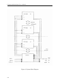
1
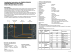
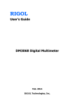
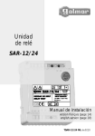
Warranty
All Chroma instruments are warranted against defects in material and workmanship for a period of
one year after date of shipment.
Chroma agrees to repair or replace any assembly or component
found to be defective, under normal use during this period.
Chroma's obligation under this
warranty is limited solely to repairing any such instrument which in Chroma's sole opinion proves
to be defective within the scope of the warranty when returned to the factory or to an authorized
service center.
Transportation to the factory or service center is to be prepaid by the purchaser.
Shipment should not be made without prior authorization by Chroma.
This warranty does not apply to any products repaired or altered by persons not authorized by
Chroma, or not in accordance with instructions furnished by Chroma.
If the instrument is
defective as a result of misuse, improper repair, or abnormal conditions or operations, repairs will
be billed at cost.
Chroma assumes no responsibility for its product being used in a hazardous or dangerous manner
either alone or in conjunction with other equipment.
be dangerous if misused.
High voltage used in some instruments may
Special disclaimers apply to these instruments.
Chroma assumes no
liability for secondary charges or consequential damages and in any event, Chroma's liability for
breach of warranty under any contract or otherwise, shall not exceed the purchase price of the
specific instrument shipped and against which a claim is made.
Any recommendations made by Chroma for use of its products are based upon tests believed to be
reliable, but Chroma makes no warranty of the results to be obtained.
This warranty is in lieu of
all other warranties, expressed or implied, and no representative or person is authorized to
represent or assume for Chroma any liability in connection with the sale of our products other than
set forth herein.
CHROMA
ATE
INC.
43 Wu-Chuan Road, Wu-Ku
Industrial Park, Taipei, Taiwan
Tel: 886 -2-2298-3855
Fax: 886-2-2298-3596
www:http://www.chromaate.com
E-mail:[email protected]
SAFETY SUMMARY
The following general safety precautions must be observed during all phases of operation , service ,
and repair of this instrument. Failure to comply with these precautions or specific WARNINGS
given elsewhere in this manual will violate safety standards of design , manufacture , and intended
use of the instrument.
Chroma assumes no liability for the customer‘s failure to comply with these requirements.
BEFORE APPLYING POWER
Verify that the product is set to match with the line voltage.
PROTECTIVE GROUNDING
Make sure to connect the protective grounding to prevent an electric shock before turning on the
power.
NECESSITY OF PROTECTIVE GROUNDING
Never cut off the internal or external protective grounding wire, or disconnect the wiring of
protective grounding terminal. Doing so will cause a potential shock hazard that may bring
injury to a person.
FUSES
Only fuses with the required rated current , voltage , and specified type normal blow , time delay ,
etc. can be used. Do not use different fuses or short-circuited fuseholders. To do so might
cause a shock or fire hazard.
DO NOT OPERATE IN AN EXPLOSIVE ATMOSPHERE
Do not operate the instrument in the presence of flammable gases or fumes.
DO NOT REMOVE THE COVER OF THE INSTRUMENT
Operating personnel must not remove the cover of the instrument. Component replacement and
internal adjustment can be done only by qualified service personnel.
WARNING
LETHAL VOLTAGES. Ac sources can supply 707 V peak at their output.
DEATH on contact may result if the output terminals or circuits
connected to the output are touched when power is applied.
SAFETY SYMBOLS
DANGER - High voltage .
Explanation To avoid injury, death of personnel, or damage to the instrument,
the operator must refer to an explanation in the instruction manual .
Protective grounding terminal To protect against electrical shock in case of
a fault. This symbol indicates that the terminal must be connected to ground
before operation of equipment.
WARNING
A WARNING sign denotes a hazard. It calls attention to a procedure,
practice, condition or the like which may result in injury or death of personnel if
it is not rightly observed.
Table of Contents
1. GENERAL INFORMATION............................................................................. 1-1
1.1 Introduction ....................................................................................................................................... 1-1
1.2 Description ......................................................................................................................................... 1-1
1.3 Key Features ...................................................................................................................................... 1-1
1.4 Specifications...................................................................................................................................... 1-2
1.5 Names of Parts ................................................................................................................................... 1-5
1.5.1 The Front Panel............................................................................................................................ 1-5
1.5.2 The Rear Panel............................................................................................................................. 1-7
2. INSTALLATION .............................................................................................. 2-1
2.1 Inspection ........................................................................................................................................... 2-1
2.2 Preparation for the Use..................................................................................................................... 2-1
2.3 Requirements of Input Power .......................................................................................................... 2-1
2.3.1 Ratings ......................................................................................................................................... 2-1
2.3.2 Input Connection ......................................................................................................................... 2-2
2.4 Output Connection ............................................................................................................................ 2-3
2.5 Remote Sense Connection ................................................................................................................. 2-6
2.6 The Procedures of Power-on ............................................................................................................ 2-7
3. LOCAL OPERATION...................................................................................... 3-1
3.1 Introduction ....................................................................................................................................... 3-1
3.2 Operation through Keypad .............................................................................................................. 3-1
3.2.1 Introduction.................................................................................................................................. 3-1
3.2.2 Data Entry.................................................................................................................................... 3-2
3.2.3 Output Setting.............................................................................................................................. 3-3
3.2.3.1 Setting Output Voltage and Frequency ................................................................................ 3-4
3.2.3.2 The Setting of Output Relay ................................................................................................ 3-6
3.2.3.3 The Output Status .................................................................................................................3-6
3.2.3.4 The Programming of 3-Phase Unbalanced Voltage .............................................................3-6
3.2.4 The Setting of Configuration........................................................................................................3-7
3.2.4.1 Remote Sense .......................................................................................................................3-7
3.2.4.2 External Reference ...............................................................................................................3-8
3.2.4.3 GPIB Address .......................................................................................................................3-9
3.2.4.4 The Setup of RS-232C..........................................................................................................3-9
3.2.4.5 The Saving..........................................................................................................................3-10
3.2.4.6 The Recalling......................................................................................................................3-10
3.2.4.7 More ...................................................................................................................................3-11
3.2.5 The Setting of Setup ...................................................................................................................3-11
3.2.5.1 The Output Range...............................................................................................................3-12
3.2.5.2 The Data Lock ....................................................................................................................3-12
3.2.5.3 The Setup of Buzzer ...........................................................................................................3-13
3.2.5.4 Protection............................................................................................................................3-13
3.2.5.5 The Saving/Recalling..........................................................................................................3-14
3.2.5.6 The SYSsetting ...................................................................................................................3-15
3.3 Applications ......................................................................................................................................3-15
3.3.1 The Execution of Output ............................................................................................................3-15
3.4 Measurement ....................................................................................................................................3-16
3.4.1 The Selection of Measurement Items .........................................................................................3-16
3.4.2 Measurement Functions..............................................................................................................3-18
3.5 Protection ..........................................................................................................................................3-19
Chroma 6460/6463/6490 User’s Manual
1. General Information
1.1 Introduction
This manual describes five major things of the Chroma 6460/6463/6490 programmable ac
source. They are specifications, installation, instructions on operation and theory of
operation. In the manual the term, AC source, is applied to the Chroma 6460/6463/6490
programmable ac source.
1.2 Description
The series of AC source is a high efficiency programmable ac power source, which is
capable of simulating a wide variety of AC line conditions and accurate measurement of
power. The microprocessor-controlled waveform oscillator generates accurate, stable
output voltage and frequency. The PWM design of power stage allows for full
volt-ampere into loads. The front panel has both RPG (rotary pulse generator) and
keypad controls for setting the output voltage and frequency. The LCD provides a
complete operating state of the unit to the user. Remote programming is accomplished
either through the GPIB bus or the RS-232C serial port.
1.3 Key Features
A. Configuration
z
z
z
z
z
Local operation from the keypad on the front panel.
Remote operation via GPIB or RS-232C interface.
Protection against Over-power, Over-load, Over-temperature, and Fan-fail.
Temperature-controlled fan speed.
Built-in output isolation relays.
B. Input/Output
z
z
z
z
Selective output voltage with full scale of 150V/300V for 6463/6490, and
150V/300V/500V for 6460.
Remote control by the use of analog voltage reference.
Full-page display of setup and measurement results.
Measurement of V, I, F, P, CF, and PF.
1-1
Chroma 6460/6463/6490 User’s Manual
1.4 Specifications
The operation specifications of the model 6460/6463/6490 are listed below (on the next
page). All specifications have been tested according to the standard Chroma test
procedures. All specifications are based on a remote sense connection, 25 ± 1°C, and
resistor load unless specified otherwise.
1-2
Chroma 6460/6463/6490 User’s Manual
Model
6460
6463
6490
OUTPUT PHASE
1 ( parallel or series )
1 or 3 selectable
1 or 3 selectable
OUTPUT RATINGS
Power / Phase
6000VA
2000VA
3000VA
Range/Phase
150V/300V(parallel)
300V/500V(series)
150V/300V
150V/300V
Accuracy
0.2% of F.S.
0.2% of F.S.
0.2% of F.S.
Resolution
0.1V
0.1V
0.1V
Distortion
1%
1%
1%
Line Regulation
0.1%
0.1%
0.1%
Load Regulation
0.2%( series )
0.8 %(parallel)
0.2%(3 phases)
0.8%( 1 phase)
0.2%(3 phases)
0.8%( 1 phase)
Voltage
Temp. coefficient
0.02%per
0.02%per
0.02%per
Max. current/phase
rms
60A/30A/15A
(150V/300V/500V)
20A/10A
(150V/300V)
30A/15A
(150V/300V)
peak
180A/90A/45A(45-100Hz)
60A/30A (45-100Hz)
90A/45A(45-100Hz)
150A/75A/38A(>100-1KHz)
50A/25A(>100-1KHz)
75A/38A(>100-1KHz)
Range
45-1KHz
45-1KHz
45-1KHz
Accuracy
0.15%
0.15%
0.15%
Resolution
0.01Hz (45-99.9Hz)
0.01Hz (45-99.9Hz)
0.01Hz (45-99.9Hz)
0.1Hz (100-999.9Hz)
0.1Hz (100-999.9Hz)
0.1Hz (100-999.9Hz)
Frequency
INPUT RATINGS
Voltage Range
190-250V ,3φ
190-250V ,3φ
190-250V ,3φ
Frequency Range
47-63Hz
47-63Hz
47-63Hz
Current
35A Max./Phase
24A Max./Phase
35A Max./Phase
0.97 Min.under full load
0.98 Min.under full load
Power Factor
MEASUREMENT
Voltage/Phase
Range
0-150V/0-300V
0-150V/0-300V
0-150V/0-300V
Accuracy(rms)
0.1%F.S.+0.25%
0.1%F.S.+0.25%
0.1%F.S.+0.25%
Resolution
0.1V
0.1V
0.1V
Range(peak)
0-140A
0-100A
0-140A
Accuracy(rms)
0.1%F.S.+0.4%
0.15%F.S.+0.4%
0.1%F.S.+0.4%
Current/phase
1-3
Chroma 6460/6463/6490 User’s Manual
Accuracy(peak)
0.2%F.S.+0.4%
0.3%F.S.+0.4%
0.2%F.S.+0.4%
Resolution
0.01A
0.01A
0.01A
Accuracy
1%F.S.(CF<6)
1%F.S.(CF<6)
1%F.S.(CF<6)
Resolution
0.01W
0.01W
0.01W
Range
45-1K Hz
45-1K Hz
45-1K Hz
Accuracy
0.01%+2count
0.01%+2count
0.01%+2count
Resolution
0.01Hz
0.01Hz
0.01Hz
Power/phase
Frequency
OTHERS
Efficiency
80% typ.
80% typ.
80% typ.
Protection
OPP,OLP,OTP,
FAN Fail
OPP,OLP,OTP,
FAN Fail
OPP,OLP,OTP,
FAN Fail
Temperature
Operating
0-40
0-40
0-40
Storage
-40 to +85
-40 to +85
-40 to +85
SAFETY
CE ( INCLUDE LVD and EMC REQUIREMENT )
Remarks
*1 : Maximum distortion for voltage varies from half to full range with linear load.
*2 : Test with sinewave and remote sense.
1-4
Chroma 6460/6463/6490 User’s Manual
1.5 Names of Parts
1.5.1 The Front Panel
Figure 1-1 The Front Panel
1-5
Chroma 6460/6463/6490 User’s Manual
Table 1-1 The Description of the Front Panel
Item
Symbol
1
Description
Display : The LCD is to display configuration, output setup, and
measurement results.
2
Soft keys : Five soft keys are located at the right side of the
LCD.
Each of them gives a command as indicated on the
corresponding command block on the LCD next to the soft keys
to guide the user unless that block is blank.
Each valid soft
key denotes the command string lying within the symbol of a
soft key; for exmaple, CONFIG
represents that the soft key
next to command block “CONFIG” is for entering configuration
menu.
Ï
3
Í
Cursor moving keys : These four keys are to move the cursor to
Î
Ð
different directions respectively.
In normal mode (non-editing
mode), pressing any of these four keys will change the place of
the cursor.
In editing mode, pressing Í or Î will move the
cursor from digit to digit for the programming of a parameter.
4
Edit
Edit command key : Pressing this key will make the user
enter into or quit from editing mode while he is programming
V or F.
5
Local
Local command key : Pressing this key will switch the control
of the AC source from remote operation to operation throguh
the keypad on the front panel.
Up and down keys : Press ▲ to search upward for the
6
▲ and ▼
desired programming parameter.
Press
▼
to search
downward.
7
0 to 9 ,and y
Numeric and decimal keys : The user can program numeric data
by pressing the digital keys and the decimal key.
8
9
ENTER
ENTER key : It is to confirm the setting of parameters.
RPG : The user can input programming data or options by
turning the RPG to the desired ones.
10
Airflow inlets : Cool airflow enters the AC source through these
holes.
11
1-6
Main power switch : It is to power on or off.
Chroma 6460/6463/6490 User’s Manual
1.5.2 The Rear Panel
Figure 1-2 The Rear Panel
1-7
Chroma 6460/6463/6490 User’s Manual
Table 1-2 The Description of the Rear Panel
Item
Name
1
Label
Description
The label includes model number, series number of the AC
source and input ratings.
2
Printer Port
The 25-pin, D-type female connector is for transferring
measurement data to a parallel printer.
3
Ext. Ref.
The BNC connector inputs control waveform amplitude from
external devices.
4
RS-232C
The 9-pin, D-type female connector transfers control commands
to and from the remote PC for remote operation.
5
GPIB Connector A remote controller using GPIB bus is connected to the AC
source through this connector for remote operation.
6
Special I/O
The 25-pin, D-type male connector transfers control signals
(trigger, remote inhibit, and transient) and 3-phase, parallel
operation signals.
7
8
9
System I/O
Three BNC connectors are for 3-phase and parallel connectivity.
Output Connector This connector outputs power to the loading device.
Remote Sense
Connector
It senses directly at the terminals of the load to eliminate any
voltage drop on the connecting cable.
Make sure of connecting
the terminal “L” of the remote sense connector to the terminal
“L” of the load, and the “N” to the “N” of the load.
Reverse
polarity is not allowed.
10
Power Line in
Connector
11
Cooling Fan
Power line input is connected to the AC source through this
connector.
Its speed automatically increases or decreases as temperature
rises or falls.
12
1-8
Safety Cover
It is to protect the user from being shocked.
Chroma 6460/6463/6490 User’s Manual
2. Installation
2.1 Inspection
After unpacking the instrument, please inspect any damage that may have occurred during
the shipment. Save all packing materials in case the instrument has to be returned one
day.
If any damage is found, please file a claim with the carrier immediately. Do not return
the instrument to the factory without obtaining the prior RMA acceptance from Chroma.
2.2 Preparation for the Use
In the beginning, the instrument must be connected with an appropriate AC line input.
Then, since it is intelligently cooled by fans, it must be installed in sufficient space for
circulation of air. It should be used in an area where the ambient temperature does not
exceed 40°C.
Before connecting input/output cable, the user must remove the safety cover mounted on
the rear downside panel first. Then, he has to refer to sections 2.3.2, 2.4, and 2.5 for
corresponding cable connection. After completion of the connection, he should mount
the safety cover on the rear panel again.
2.3 Requirements of Input Power
2.3.1 Ratings
Input Voltage Range
:
Input Frequency
Max. Current
:
:
190-250 VLL , 3 phases 4 wires ∆, or
329-353 VLL , 3 phases 5 wires Y
47-63 Hz
6460/6490 : 23 A; 6463 : 16A
Caution : The AC source will be damaged if it is operated at an input voltage that is
outside its configured input range.
2-1
Chroma 6460/6463/6490 User’s Manual
2.3.2 Input Connection
The input terminal block is located on the rear downside panel of the instrument. The
power cord must be rated at least for 85°C. The power line input must have a current
rating which is greater than or equal to the maximum current rating of the AC source.
*** CAUTION ***
There are two different input voltage rating models. One is 380 VLL
3 phases 5 wires (Y), and another is 220 VLL 3 phases 4 wires (∆). Be
careful to verify that what kind of the model you have, and make sure that
the main voltage is correct for the model.
See figure 2-1 (on the next page) and do the following things one by one:
1.
2.
3.
4.
5.
6.
Remove the safety cover from the back downside of the AC source.
Open the line clamp on the safety cover, and screw the power cord to the instrument
through the cable gland.
Position the power cord, and tighten the cable gland to secure the clamp.
Connect the ac lines to the terminal blocks of the AC source as figure 2-1.
If you need to connect the load to the AC source, please refer to section 2.4 for output
connection.
Slip the safety cover over the ac input terminal strip, and secure the cover with two
screws.
*** WARNING ***
To protect the operators, the wire connected to the GND terminal must be
connected to the earth ground. Under no circumstances shall this AC
source be operated
without an adequate ground connection.
Installation of the power cord must be done by a professional and in accordance with local
electrical codes.
2-2
Chroma 6460/6463/6490 User’s Manual
Figure 2-1-a
Figure 2-1-b
6460/6463/6490 220 3∼∆ Input Connection
6460/6463/6490 380 3∼Y Input Connection
2.4 Output Connection
The output terminal block is located in the rear downside of the AC source. Load
connection to the AC source is done at the output terminals. To meet the safety
requirements the wires to the load must be sufficiently large gauges, so they will not
overheat while carrying the output current. See figure 2-2 on the next page.
2-3
Chroma 6460/6463/6490 User’s Manual
Figure 2-2-a
Figure 2-2-b
2-4
6463/6490 Three-Phase Output Connection
6463/6490 One-Phase Output Connection
Chroma 6460/6463/6490 User’s Manual
Figure 2-2-c
6460 Series Output Connection (Note: VLOAD=2×Vset)
Figure 2-2-d
6460 Parallel Output Connection
2-5
Chroma 6460/6463/6490 User’s Manual
Table 2-1 The Characteristics of AWG (American Wire Gauge) Copper Wire
Capacity 1
AWG No.
Capacity 1
14
25 A
8
60 A
12
30 A
6
80 A
10
40 A
4
105 A
AWG No.
1. Capacity is based on the ambient temperature of 30°C with the conductor rates at 60°C.
2.5 Remote Sense Connection
The remote sense function of the AC source monitors the voltage at the load instead at the
output terminal of the AC source for 6460 series mode and 6463/6490 3-phase mode. It
ensures the delivery of accurate voltage as programmed at the load by automatically
compensating the output voltage drop over the connecting cable. The user has to set
Remote Sense ON so as to enable this function.
Connect the sensing leads from the “∅1”, “∅2”, “∅3” and “COM” terminals on the
remote sense to the load as shown in Figure 2-2 (on the previous page).
Because the
sensing leads carry only a few milliamperes, the wires for sensing are much lighter than
the load leads.
The sensing leads are part of the feedback path of the AC source, so they
must be kept at a low resistance in order to maintain the best performance.
sensing leads carefully so that they will not be open-circuited.
Connect the
If the sensing leads are
left unconnected or become open-circuited during operation, the AC source will disable
the output, and display “OPEN INT”.
The sensing leads must be a twisted pair to
minimize the pickup of external noise.
The sensing leads need to be connected to the
load as close as possible.
AC source.
2-6
The user must press ENTER over two seconds to reset the
Chroma 6460/6463/6490 User’s Manual
2.6 The Procedures of Power-on
*** WARNING ***
Before turning on the instrument, all protective earth terminals, extension cords, and
devices connected to the instrument must be connected to a protective earth ground.
Any
interruption in the protective earth grounding will cause a potential shock
hazard
that might injure a person.
Apply the line power, and turn on the power switch on the front panel. No load shall be
connected to the output terminal block. The AC source will do a series of self-tests every
time the power switch is turned on.
After the routines of the self-test are done, the display will show an “OK” at the right side
of each test item indicating that the item is no problem as follows:
CHROMA
programmable AC source Model 6490
MODEL NO. : 64900000 VER:1.00
Self test :
HECKSUM:FAB6
Φ3
ROM test
RAM1 test
RAM2 test
Waveform
Frequency
Status Check
Φ1
OK
OK
OK
OK
OK
OK
Φ2
OK
OK
OK
OK
OK
OK
OK
OK
OK
OK
OK
OK
NEXT
If any failure is detected on a certain item, an “NG” will be shown at the right side of that
item, and the sound of “beep” will be heard. It takes about eight seconds to complete the
routines of the self-test. If no error is found, the LCD will display as follows:
2-7
Chroma 6460/6463/6490 User’s Manual
CHROMA
programmable AC source Model 6490
OUTPUT
SETTING
00V=0.0
04 26
Φ11
300V
F=60.0
CONFIG
Output relay=OFF
Output status=PAUSE
V1
0.01
I1
0.01
P1
0.11
V3
=
Output Measurements
0.05
V2
=
=
0.01
I2
=
=
0.23
P2
=
=
0.14
F
=
DISP
SET UP
RUN
The following table shows all the error messages and recommended actions:
Item
Error Message
Description
Action
1 Rom test NG
System memory test fails.
Consult your dealer for assistance.
2 Waveform test NG
Waveform circuit test fails. Consult your dealer for assistance.
3 Frequency test NG
Frequency test fails.
Consult your dealer for assistance.
4 RAM1/RAM2 test NG Battery back-up memory Press 0 , 8 simultaneously to
test fails, or memory is bad.
initialize memory.
The
NG
phase
interface
test
5 Status Check NG
Consult your dealer for assistance.
fails.
*** NOTICE ***
If you initialize memory, all of the saved data may be initialized, therefore you
must check the saved data before doing so.
2-8
Chroma 6460/6463/6490 User’s Manual
2-9
Chroma 6460/6463/6490 User’s Manual
3. Local Operation
3.1 Introduction
The AC source can be configured to operate in local or remote mode. The operation in
remote mode through a remote GPIB controller or RS-232C will be described in Section
Six. In this section the operation in local mode through the keypad on the front panel for
data entry and test is going to be described. The AC source is configured for local
operation when it is turned on.
3.2 Operation through Keypad
3.2.1 Introduction
The AC source provides the user-friendly programming interface using the keypad on the
front panel to the user. Each display of the LCD on the AC source, which represents an
operational menu, is divided into three zones.
(1) Headline : It displays characters in reverse video on the first row of the LCD. This
line provides information including current operation function, output parameters, and
the total operation time after power-on.
(2) Command zone : The farthest right column of the LCD is divided into five blocks.
Each block represents a soft key for a minor function, which can be executed by
pressing the key next to it. Hence, all the command sets are structured as a
command
tree. Each node of the command tree presents an operational menu.
Also, on each
node the LCD always provides the user with five choices to let
him enter into other
nodes, or quit from the current node.
Sample nodes (operational menu) and the command tree are shown below:
3-1
Chroma 6460/6463/6490 User’s Manual
The command tree:
Output setting menu
CONFIG
MORE
SAVE
RECALL
QUIT
DISP
QUIT
SET UP
SYSset
SAVE
RECALL
QUIT
RUN/PAUSE
(3) Parameters zone : The remaining area offers information which guides the user to
program the AC source, to view the current status, to collect measurement results, etc.
3.2.2 Data Entry
Before describing each menu, the operations common in the parameters zone will be
explained below:
Movement of Cursor
Use any of the cursor moving keys: Ï, Ð, Í, Îto move the cursor to the desired
parameter for programming.
There are two ways for the user to set the parameters. One is in normal mode, and
another in editing mode. The following example is how to set output voltage.
3-2
Chroma 6460/6463/6490 User’s Manual
Normal Mode
(1) Press the desired numeric keys of 1 , 3 , 5 , . , 2 , ENTER to set
V=135.2V.
(2) Press ▲ or ▼ key repeatedly, or keep pressing any of them until the desired
value,V=135.2V, is shown on the LCD.
Then, press ENTER to confirm.
Increase
or decrease value is done through the use of the farthest right digit.
*** NOTICE ***
If a parameter is modified, the user has to press ENTER to update the current data
and save them into memor, otherwise the old data will remain when he exits from the
machine.
Editing Mode
Display of Cursor
In editing mode the user can set parameters
60.0
immediately without pressing ENTER to confirm.
The mode only allows the user to set V or F parameter.
When the user moves the cursor to V parameter, and
presses Edit to enter into the editing mode, the cursor
V=135.2_
F=
will show as right:
Set the output voltage as 132.2V as follows:
Move the cursor to the position of digit 5 using Í , and press 2 to set V=132_.2.
Press Edit to enter into editing mode.
Editing mode is useful when you want to
change V or F parameter only one digit, or to set output V or F in step change. In this
mode the user can increase or decrease the value of current position by pressing ▲ , ▼
or PRG too.
Press Edit agian to quit from editing mode.
3.2.3 Output Setting
3-3
Chroma 6460/6463/6490 User’s Manual
The Output Setting on the screen is the main operation menu in the AC source, which
accepts AC output parameters, including V, F Sync. source, etc. In this menu the user
can activate the AC source by pressing the soft key of RUN , and obtain the measured
results at the terminals of the devices under test.
3.2.3.1 Setting Output Voltage and Frequency
*** NOTICE ***
The maximum output voltage of ONE power stage is limited by the peak value of
the waveform, which is about 425 Vpeak. 6463, 6490 have three power stages that
can be selected in three phases or one phase (parallel). 6460 has two power stages
that can be selected in series or parallel. The output is programmed in units of
RMS volts. For a sine wave, the maximum AC voltage of ONE power stage that
can be programmed is 300 V. So, for 6463, 6490 the max. Line to Line voltage is
519 Vrms in 3-phase mode, and 300 Vrms in 1-phase mode. For 6460 the max.
voltage is 300 Vrms in parallel mode, 500 Vrms in series mode. The set voltage
that we program here is just for each power stage. If we want to get 400 Vrms
output of 6460 in series mode, we have to program 200 V on the display. For
other waveforms, the max. voltage may be different.
When you turn on the AC source, the state of default output is set in the Configure menu of
Power on output status. Set the output as V=135.2 Vrms, F=50.0 Hz as follows:
1. After you have powered on the AC source, and accomplished the self-test (or exited
from any other menu by pressing QUIT ), the LCD will display a main operational
picture on the screen as follows (on the next page) :
3-4
Chroma 6460/6463/6490 User’s Manual
CHROMA
OUTPUT
programmable AC source
SETTING
00V=0.0
05 55
Φ11
300V
F=60.0
Model
CONFIG
Output relay=OFF
Output status=PAUSE
V1
0.01
I1
0.01
P1
0.17
V3
=
Output Measurements
0.05
V2 =
=
0.01
I2
=
=
0.23
P2
=
=
0.13
F
=
DISP
SET
UP
RUN
Display of Cursor
The line where the cursor stays indicates that the AC
source is waiting for the input of the voltage value.
2.
V= _ 0.0
Input the value of V as 135.2 by pressing 1 , 3 , 5 ,
. , 2 , ENTER to set voltage of 135.2 Vrms , or
using data entry in section 3.2.2.
V=135.2
3. Move the cursor to set frequency by inputting
the value of F as 50 Hz, and pressing 5 , 0 ,
V= 135.2
F= _ 60.00
F=
50.00
ENTER .
*** NOTICE ***
Voltage ranges from 0 to 300 V in step of 0.1 V.
1000 Hz in step of 0.01/0.1Hz.
Frequency ranges from 45 to
3-5
Chroma 6460/6463/6490 User’s Manual
3.2.3.2 The Setting of Output Relay
There is a relay on the output of the AC source for the connection with a load. When
output relay is “ON”, it means that the output relay is closed in spite that the output status
of the AC source is in QUIT mode. When output relay is “OFF” , it means that the
output relay is closed only as the output status is in RUN mode. If the output status
is in QUIT mode, the output relay will be open.
To set the output relay as ON as follows:
1. Move the cursor to the command of output relay.
2. Press ▲ , ENTER to set output relay ON.
A
click sound will be produced from the AC source
when output relay is activated.
3.2.3.3
Output relay=OFF
Output relay=ON
The Output Status
There are two status of output. One is PAUSE, and another is RUN.
PAUSE: It means the output of the AC source is inactive.
RUN : It means the output of the AC source is active according to the user’s set
parameters.
3.2.3.4 The Programming of 3-Phase Unbalanced Voltage
Only for the 3-phase mode in 6463 and 6490, you can program the 3-phase output with
different voltage:
1. Move the cursor to the command of phase select.
phase
select = ∅1
2. Press ▲ or ▼ to set ∅1, and press ENTER .
3. Set the voltage for ∅1.
4. Repeat 1, 2, 3 for ∅2 and ∅3 with the set voltage you desire.
Then, press RUN , you will get the different voltage as
3-6
Chroma 6460/6463/6490 User’s Manual
you program at the output.
5. If you choose ∅1+∅2+∅3, the programmed voltage will be
for all three phases.
3.2.4 The Setting of Configuration
The AC source provides the user with a lot of useful features such as Remote sensing,
External reference, etc. To use these powerful features the user must program relevant
parameters according to the needs of application using the configuration setup .
Press the soft key,
CONF
CHROMA
, the LCD displays the following picture:
programmable AC source Model 6490
Configure setting
00External
00 25 ref . =OFF
Remote sense
=OFF
GPIB address =30
RS232C
Baudrate=9600
MORE
SAVE
parity=NONE
RECALL
QUIT
3.2.4.1 Remote Sense
Remote sensing is to eliminate voltage drop on the connection cables from the output
terminal of the AC source to that of the load. For the details of wire connection please
refer to section 2.5. The procedures of setup are shown below:
1. Move the cursor to the command of Remote Sense.
Remote Sense =OFF
2. Press ▲ , ENTER to change the option from OFF
to ON.
Remote Sense =ON
3-7
Chroma 6460/6463/6490 User’s Manual
*** NOTICE ***
1. For 6460 in “parallel” mode and 6463/6490 in “ONE phase” mode there is no
“remote sense” function.
2. Befor choosing “ON” for enabling the function of remote sense, the remote
sensing leads must be connected to the load (see 2.5), otherwise the AC source
will detect the error and stop output.
3.2.4.2 External Reference
The AC source allows the user to make use of the controlled signal from external devices
for the setting of its output. The BNC connector of the external reference on the rear
panel lets the user apply DC signal to the AC source for the setting of output voltage.
The output voltage (Vout) responses linearly proportional to the controlled DC level with
voltage ranging from 0 to 10 V. Vout can be calculated using the following formula:
Vout = Vcontrol / 10 V × V range.
To set Vout to 60Vrms:
1. Select range = 300V in setup menu, apply external DC = 2V, and Vout = 60Vrms.
2. Select range = 150V in setup menu, apply external DC = 4V, and Vout =60Vrms.
The procedures of setup are shown below:
1. Move the cursor to the command of External ref.
External ref. =OFF
2. Press ▲ , ENTER to change the option from
OFF to ON.
External ref. =ON
*** NOTICE ***
When external ref. is set as ON, the output voltage (Vout) will respond to the
external control DC voltage level. The user cannot control Vout amplitude
3-8
Chroma 6460/6463/6490 User’s Manual
through the keypad on the front panel until external ref. is set as OFF again.
However, he can still program and output other parameters.
3.2.4.3 GPIB Address
The AC source offers the mode of remote operation too. For details please refer to
Chapter Five. Prior to remote operation the user has to set the GPIB address 10 as
follows:
1. Move the cursor to the command
line of GPIB address.
GPIB address =30
2. Press 1 , 0 , ENTER to set address
10.
GPIB address =10
*** NOTICE ***
Addressing space ranges from o to 30.
3.2.4.4 The Setup of RS-232C
The AC source offers another remote operation through the RS-232C bus.
tion protocol is set as follows:
Communica-
To set baud rate=19200, parity=ODD.
1. Move the cursor to the command
line of Baudrate.
Baudrate=4800
Parity=EVEN
Baudrate=19200
Parity=EVEN
Baudrate=19200
Parity=ODD
2. Press ▲ or ▼ or turn RPG to
select 19200, then press ENTER .
3. The cursor moves automatically to
the setting position of “parity”.
Press ▲ or ▼ or turn RPG to
select “ODD”, then press ENTER .
3-9
Chroma 6460/6463/6490 User’s Manual
*** NOTICE ***
The options of baud rate are 2400/4800/9600/19200.
EVEN/ODD/NONE.
The options of parity are
3.2.4.5 The Saving
To save all of the system data as follows:
1. Press
right.
SAVE
, and the LCD displays as
Save to group
0
2. Press the numbers from 0 to 2 on the numeric
keypad to select a desired memory group.
3. Press ENTER to confirm it.
*** NOTICE ***
1. Selection of memory group is programmable by pressing the numeric keypad
only. Other methods, including the turning of rotary knob and the pressing
of ▲ or ▼ , are invalid when the user tries to program a memory group to
be “Saved” or “Recalled”.
2. The AC source provides three memory groups: 0, 1, and 2. The memory group
0 keeps power-on defaults. The setups saved into the memory group 0 will be
recalled automatically when the AC source is powered on again while those
saved into other memory groups must be recalled manually.
3.2.4.6 The Recalling
To recall the system data as follows:
1. Press
3-10
RECALL
, and the LCD displays
Recall from group
0
Chroma 6460/6463/6490 User’s Manual
as right.
2. Press the numeric keypad to select a desired
memory group.
3. Press ENTER to confirm it.
3.2.4.7 More
Press the soft key of
the waveform .
MORE
to enter into another display to select output phase and
3.2.4.7.1 The Selection of Phase Status
In 6460 there are two modes, “parallel” and “series”, for choice. In 6463, 6490 there are
two modes, “one phase” and “three phase”, for choice too. If you choose “three phase”
and press ENTER , there will be ∅2=120.0, ∅3=240.0 appearing at the downside of the
display. They are the phase shift of ∅2 and ∅3 reference to ∅1, and can be programmed
as you like.
Note : You can easily verify the mode you are using from the headline of the output main
menu.
∅13 : “series” mode for 6460 and “3-phase” mode for 6463, 6490.
∅11 : “parallel” mode for 6460 and “1-phase” mode for 6463, 6490.
3.2.5 The Setting of Setup
The operational menu of “SET UP” manages the setups for V full range, waveform, data
lock, protections, etc. Press SET UP to enter into the menu of “SET UP”, and the
LCD will display as follows:
3-11
Chroma 6460/6463/6490 User’s Manual
CHROMA
programmable AC source Model 6490
SETUP PARAMETERS
00Range=
04 35300V
Data lock = OFF
SYSset
Buzzer = ON
PROTECTION
Current limit= 15.00
delay time= 0.0 sec
Voltage limit=300.0
SAVE
RECALL
QUIT
3.2.5.1 The Output Range
The AC source supplies full range of output voltage with two options of 150 V or 300 V.
To set the range of output voltage as 150 as follows:
1. Move the cursor to the command line of Range.
Range=
300
2. Press ▲ or ▼ to change the option from
“300” to “150”, then press ENTER .
Range=
150
*** NOTICE ***
The AC source will set output voltage as 0 V first in order to eliminate voltage
spike when range changes. Then, it will set output voltage as set value. It may
cause UUT to shut down or get bad if the output is active, and range changes.
3.2.5.2 The Data Lock
The AC source allows the user to lock data entries, so the pre-defined parameters can be
protected from being modified by an unauthorized person.
3-12
Chroma 6460/6463/6490 User’s Manual
The procedures for the setting of data lock are shown below:
1. Move the cursor to the command line
of “Data lock”.
Data lock
=
OFF
Data lock
=
ON
Buzzer
=
ON
2. Press ▲ , ENTER to change the
option from OFF to ON.
Buzzer
=
ON
*** NOTICE ***
The user must select OFF to unlock.
3.2.5.3 The Setup of Buzzer
The buzzer of the AC source beeps when the user presses the keypad on the front panel, or
turns the PRG knob. If the user does not need it, he can turn if off.
To turn off the buzzer as follows:
1. Move the cursor to the command line
of “Buzzer=”.
Data lock
=
off
Buzzer
=
ON
Data lock
=
off
Buzzer
=
OFF
2. Press ▲ , ENTER to change the
option from ON to OFF.
3.2.5.4 Protection
Limitation of output RMS current, output voltage, and delay time are the parameters for
triggering overload protection. The discussion of protection/limitation in this subsection
is about user-programmable protection, not hardware protection.
The procedures for setting Current limit = 20A, Delay time = 1 sec., and Voltage limit =
250V are described below:
1. Move the cursor to the command line
3-13
Chroma 6460/6463/6490 User’s Manual
of “Current limit=”.
Current limit= _15.00
2. Press 2 , 0 , ENTER to change
the value to “20.00”.
Current limit=20.00
3. The cursor moves to the command line
of “delay time=” automatically.
delay time=
_0.0 sec
delay time=
1.0 sec
4. Press 1 , ENTER to change the
value to “1.0”.
5. The cursor moves to the command line
of “Voltage limit=” automatically.
Voltage limit
=
150.0
6. Press 2 , 5 , 0 , ENTER to
change the value to “250.0”.
Voltage limit =250.0
*** NOTICE ***
1.
Delay time is valid for eliminating transient current spike, which is useless in
voltage protection.
2.
Current limit ranges from 0 to 100 in step of 0.01 A.
Delay time ranges from 0 to 100 in step of 0.1 sec.
Voltage limit ranges from 0 to 300 in step of 0.1 V.
3.
The output of the AC source will be disabled when protection is active, and
will remain so even the condition is released. The user has to press ENTER
for over two seconds to reset the AC source.
3.2.5.5 The Saving/Recalling
Please refer to 3.2.4.5 and 3.2.4.6 for related information.
3-14
Chroma 6460/6463/6490 User’s Manual
3.2.5.6 The SYSsetting
This function is reserved for maintenance and factory testing only.
3.3 Applications
3.3.1 The Execution of Output
In the main operational menu of output, the user can press the soft key RUN to enable
the execution of output. When the user presses RUN , the LCD will change from
“Output status=PAUSE” to “Output status=RUN”, and the command string of the original
“RUN” will change to “PAUSE” (Push the soft key PAUSE to disable output when
output is in “RUN”). The following example of LCD indicates the states when the user
toggles the output between “RUN” and “PAUSE” by the soft key. If the output is
inactive, the LCD will show as follows :
CHROMA
programmable AC source
Model
OUTPUT SETTING 300V WAVE=A Φ11 00:00:45
SETTING
150V
Φ11
V=110.0
F=60.0
00V=110.0
01 41
CONFIG
F=60.0
Sync.source=phase phase=
90.0
CONFIG
Output relay=ON
Output relay=ON
MODE
status=PAUSE
Output
Output status=PAUSE
OUTPUT
V1
0.02
I1
0.01
P1
0.08
V3
Press
RUN
Output Measurements
Output
=
0.1
F
V Measurements
= 60.00
0.02
V2 =
I
=
0.00
P
= 0.12
0.02
I
2
=
0.06
IP IP+ = = 0.12
0.11
P2
=
CF = ---------PF
= 0.08
F
=
DISP
=
DISP
=SET UP
SET
UP
=RUN
=
RUN
to enable the active output, and the LCD will show as follows:
3-15
Chroma 6460/6463/6490 User’s Manual
CHROMA
programmable AC source
Model
OUTPUT SETTING 300V WAVE=A Φ11 00:00:45
SETTING
150V
Φ11
V=110.0
F=60.0
00V=100.0
03 10
CONFIG
F=60.0
Sync.source=phase phase=
90.0
CONFIG
Output relay=ON
Output relay=ON
MODE
status=PAUSE
Output
Output status=RUN
OUTPUT
V1
I1
0.06
P1
1.52
V3
60.00
I3
Output Measurements
Output
=
0.1
F
V Measurements
= 100.00
V2 = 99.79
60.00
I
=
P
= 0.04
I 20.00=
0.12
0.06 =IP IP+ = = 1.90
P2
0.12
CF = ---------PF
= 99.89
F
=
0 02
DISP
=
DISP
=SET UP
SET
UP
=RUN
=
PAUSE
PF1
*** NOTICE ***
The user may observe the measured values of the measurable items under
Output Measurements on the lower part of the LCD. For detailed description
of the measurement please refer to subsection 3.4.
3.4 Measurement
The AC source can measure the actual performance of a load connected to it without using
an extra measuring instrument. When the AC source is active, it measures the V, I, F, P,
etc. of a load of each phase. The user can select the measurement point at the connector
of a load (remote sense= ON), or at the output connector of the AC source itself.
3.4.1 The Selection of Measurement Items
The AC source can display concurrently up to 7 measurable readings, including V, P, I, CF,
PF, F, Ptot. The user can select different measurement functions to display the measured
readings. If the user selects less than three mesurement functions, the LCD will display
the measurement in enlarged characters as follows (The lower half of the main operational
menu is the display area of measuremnet):
3-16
Chroma 6460/6463/6490 User’s Manual
CHROMA
programmable AC source
Model
OUTPUT SETTING 300V WAVE=A Φ11 00:00:45
SETTING
300V
Φ11
V=110.0
F=60.0
00V=0.0
11 09
CONFIG
F=60.00
Sync.source=phase phase=
90.0
CONFIG
Output relay=ON
Output relay=OFF
MODE
status=PAUSE
Output
Output status=PAUSE
OUTPUT
V1
F
P1
Output Measurements
Output
=
0.1
F
V Measurements
60.00
=
I 0.05=
0.00
P
0.12
0.06
IP = IP+
60.00= 0.12
PF
= CF
0.35= ----------
DISP
=
DISP
=SET UP
SET
UP
=RUN
=
RUN
When the output parameters for measurement are more than three, the LCD will display in
normal characters.
The procedures for selecting the measurement functions are described below:
1. Enter into the measurement display menu by pressing the soft key
main
operation menu. The LCD displays as follows :
CHROMA
programmable AC source
MEASUREMENT
DISPLAY
Mode=continuous
=
0.04
1. V
=
0.02
2. V
=0.01
3. I
=
0.01
4. I
=
0.00
5. P
=
0.11
6. P
=
0.13
7. V
=
0.00
8. F
=
0.00
9. I
=
0.000
10. PF
=
0.08
11. P
=------------12. CF
DISP
in the
Model
00:00:21
Φ1
Φ2
Φ1
Φ2
Φ1
Φ2
Φ3
Φ3
Φ1
Φ3
Φ1
QUIT
(It is the default setting from the factory for all the measurement items.)
2. Display the readings in a continuous way, or display a single measurement per
3-17
Chroma 6460/6463/6490 User’s Manual
trigger by turning rotary knob, or pressing ▲ or ▼ key (Leave “continuous”
unchanged).
Note : If the user selects “single”, he may use
trigger.
TRIG
for measurement by manual
3. Move the cursor to the first display item .
Number : 1 in front of V means the display
position of measurement function.
1.V
=
4. Turn the rotary knob clockwise, or press ▲ , and the measurement functions will
change one by one in the following order:
V =>
P =>
I =>
CF =>
PF =>
F =>
Ptot =>
empty => (return to V)
Note 1 : Turn the rotary knob counterclockwise, or press ▼ , the item will appear in
Note 2 : The option “empty” means that nothing is displayed for a corresponding item.
5. Select a desired measurement funtion, and press ENTER to confirm.
The cursor
moves to the second column automatically.
6. You can select the phase ∅1, ∅2 (or ∅3 for 6463, 6490) by turning the rotary knob
and pressing ENTER to confirm. The cursor moves to the next item of the first
column. When you return to the main menu, these measurement items will be
displayed on the lower half of the screen as shown by the above sample.
Note : If the user selects more than three items, the odd items will be displayed on the left
column, and the even items on the right one. If the selected items are less than
or
equal to three, they will be listed with
only one column in enlarged characters.
7. Repeat step 4, 5, and 6 for the remaining items.
3.4.2 Measurement Functions
3-18
re
Chroma 6460/6463/6490 User’s Manual
The AC source offers 7 measurement functions to the user. All the functions can be
specified to display in the main operational menu as stated in the previous subsection.
The definitions of the functions are listed in the following table:
Table 3-1
Function
Available Measurement Functions
Definition
V
It is the measurement readings of Voltage in Volts.
F
It is the measurement readings of Frequency in Hertz.
I
It is the measurement readings of Current in Amperes.
P
It is the true Power meausrement in Watts.
CF
It is the Crest Factor, and its calculation formula = Ipeak/Irms.
PF
It is the Power Factor, and its calcultation formula = true power/ (Vrms × Irms)
Ptot
(true RMS measurement)
(ture RMS measurement)
It is the sum of the power of all phases = P1+P2(+P3)
3.5 Protection
The AC source provides protection for software and hardware.
listed below:
Protection
Protection for software is
Description
Current
When current is over the limit, protection is given.
Power
When power is over the limit, protection is given.
Voltage Limit
The user cannot program the voltage more than the set voltage limit.
Voltage Range Error During the operation of the AC source, this message will be displayed
when the set voltage is beyond the full scale of the current voltage range.
Protection for hardware is listed on the next page too.
3-19
Chroma 6460/6463/6490 User’s Manual
Protection
Description
PFO
INT
It is power failure protection, and means that the voltage of the
power supply is lower than specification.
FAN
INT
It is fan failure protection, and means that the cooling fan
malfunctions.
OPP
INT
It is over power protection, and means that the output stage is over
the power specification.
OCP
INT
It is over current protection, and means that the output stage is over
the current specification.
SHT
INT
It is short protection, and means that the output terminals are
shorted.
INP
INT
It is power failure protection, and means that the voltage of the input
power supply is lower than specification.
OTP
INT
It is over temperature protection, and will be enabled when the
internal temperature of the AC source is too high.
OPEN
INT
It is feedback open protection.
dV
INT
The protection happens when there is a large difference between the
set voltage and the measured one.
If any output protection mentioned above is triggered to hold normal output, please remove
the errors, then, press ENTER , and hold the key for two seconds to unlock the output
protection so as to resume the normal operation.
3-20
Table of Contents
4. THEORY OF OPERATION ............................................................................. 4-1
4.1 General Information ......................................................................................................................... 4-1
4.2 Description of Overall System .......................................................................................................... 4-1
5. REMOTE OPERATION................................................................................... 5-1
5.1 General Information ......................................................................................................................... 5-1
5.1.1 Setting the GPIB Address and RS-232C Parameters................................................................... 5-1
5.1.2 Wire Connection of RS-232C...................................................................................................... 5-2
5.2 The GPIB Capability of the AC Source........................................................................................... 5-3
5.3 Introduction to Programming .......................................................................................................... 5-3
5.3.1 Conventions ................................................................................................................................. 5-4
5.3.2 Numerical Data Formats .............................................................................................................. 5-4
5.3.3 Boolean Data Format ................................................................................................................... 5-4
5.3.4 Character Data Format................................................................................................................. 5-4
5.3.5 Basic Definition ........................................................................................................................... 5-5
5.4 Traversal of the Command Tree ...................................................................................................... 5-7
5.5 Execution Order ................................................................................................................................ 5-7
5.6 The Commands of the AC Source.................................................................................................... 5-8
5.6.1 Common Command Dictionary ................................................................................................... 5-8
5.6.2 Instrument Command Dictionary................................................................................................. 5-9
5.7 Command Summary ....................................................................................................................... 5-14
APPENDIX
PIN ASSIGNMENT OF USER INTERFACE.....................................1
Chroma 6460/6463/6490 User’s Manual
4. Theory of Operation
4.1 General Information
The AC source consists of two (6460) or three (6463/6490) power stages, and each stage
has 13 print circuit boards and other components. Each of the PCBs has its specific
function that will be described in the following subsection.
4.2 Description of Overall System
Figure 4-1 (on page 4-3) shows the overall system of each power stage. Main power
flows through the A/D, D/D, D/A power stage converter. The A/D power stage is
designated as I board, and generates DC voltage from the line input. The DC voltage of
A/D output is applied to the input of D/D power stage. The G board of D/D stage takes
power from the A/D output. It generates two isolated DC outputs for D/A power stage.
The H board of D/A inverter generates AC output through full bridge controlled by C
board to O board. The D/A power stage is through O board relays in parallel or series
control to obtain more current and higher voltage.
A board is identified as CPU. The CPU of the AC source is used to perform remote
control through GPIB, RS-232C or EXT VREF interface on Optional board, to control
output frequency and voltage through BS and C boards, to measure voltage, current and
power through BM board, to display message, to scan front panel key through LCD
module and K board, and to monitor all interrupts.
BM board is identified as measurement unit.
BS board is identified as waveform generator.
as the reference input of C board.
All measurement functions are done here.
It generates output waveforms which act
C board is identified as controller of DC to AC (H board).
stage in order to get low distorted waveform output.
It controls DC to AC power
K board is identified as keyboard which includes RPG (Rotary Pulse Generator). It is an
interface between the user and the instrument when the latter is used in local operation.
4-1
Chroma 6460/6463/6490 User’s Manual
Extended and Optional boards are identified as input/output signals which include GPIB,
RS-232C, EXT VERF, printer and other I/O control signals. Optional board is on
Extended board.
M1 board is identified as mother board which includes system power supply, fan control
circuit, and interconnection of A, BM, BS, C boards.
M2 board is simply an interconnection of M1, Extended, and O boards.
4-2
Chroma 6460/6463/6490 User’s Manual
4-3
Chroma 6460/6463/6490 User’s Manual
Figure 4-2 System Block Diagram
4-4
Chroma 6460/6463/6490 User’s Manual
5. Remote Operation
5.1 General Information
The AC source can be controlled remotely through the GPIB or the RS-232C port.
GPIB port is mostly used, but the RS-232C port is helpful too.
The
Technically speaking, the GPIB interface is quite different from the RS-232C interface.
The GPIB interface is an 8-bit parallel data bus owning a host of bus commands for
synchronization, and up to one Megabyte transfer rate. The RS-232C interface, a series
bus with a few handshake lines for synchronization, is less capable, so its requirement is
not so much, and the user can write a simple program to do basic remote control easily.
5.1.1 Setting the GPIB Address and RS-232C Parameters
The AC source is shipped with the GPIB address which is set at 30. The address can be
only changed from the front panel by pressing the soft key CONFIG in the “Configure
setting” menu. This menu is also used to select the RS-232C interface, and specify the
parameters of RS-232C such as baud rate and parity.
Set the GPIB address as follows:
1. Press CONFIG
setting” menu.
to enter into the “Configure
2. Move the cursor to the line of GPIB address.
Display of Cursor
GPIB address =30
3. Enter the new address from the numeric keys
such as 5 , ENTER , and the GPIB address
will change to 5.
GPIB address =5
5-1
Chroma 6460/6463/6490 User’s Manual
Set the RS-232C interface as follows:
1. Press CONFIG
setting” menu.
to enter into the “Configure
2. Move the cursor to RS-232C parameters of
baud rate.
Baudrate=4800
Parity=EVEN
3. Select baud rate by pressing ▲ or ▼ key,
then press ENTER .
4. Move the cursor to the line of parity, and
select parity as you select baud rate.
5.1.2 Wire Connection of RS-232C
The AC source is shipped with the baud rate which is set at 9600, and with parity which is
set as None. For RS-232C interface, only the signals of TxD, RxD, DTR, and CTS are
used for its transfer of data. The RS-232C connector is a 9-pin D subminiature female
connector. The following table describes the pins and signals of RS-232C connector.
Pin No.
Input/Output
Description
1
---
No connection
2
OUTPUT
TxD
3
INPUT
RxD
4
INPUT
DSR
5
---
GND
6
OUTPUT
DTR
7
INPUT
CTS
8
OUTPUT
RTS
9
---
No connection
Interconnection between the computer (compatible with IBM PC) and the AC source is
illustrated below:
5-2
Chroma 6460/6463/6490 User’s Manual
IBM PC
1 (DCD) X
2 (Rx) < - - - - 3 (Tx)
----->
4 (DTR) - - - - - >
5 GND - - - - - 6 (DSR) X
7 (RTS) X
8 (CTS) < - - - - 9 (RI)
X
AC source
2 (Tx)
3 (Rx)
7 (CTS)
5 GND
6 (DTR)
DTR of the AC source is inactive if receiver‘s buffer is full. It means that the AC source
will not receive any data until DTR is active. Similarly, if CTS of the AC source is
inactive, data will not be sent to the computer.
5.2 The GPIB Capability of the AC Source
GPIB Capability
Talker/Listener
Description
Interface Functions
Commands and response messages can be sent and
received over the GPIB bus.
AH1, SH1, T6, L4
Status information can be
read using a series poll.
Service Request The AC source sets the SRQ line true if there is an
SR1
enabled service request condition.
Remote/Local
The AC source powers up in local state.
In local state,
RL1
the front panel is operative, and the AC source responds to
the commands from GPIB.
In remote state, all front
panel keys except the local key are disabled.
key to return the AC source to local state.
Press local
Local key can
be disabled using local lockout so that only the controller
or the power switch can return the AC source to local
mode.
5.3 Introduction to Programming
All commands and response messages are transferred in form of ASCII codes. The
response messages must be read completely before a new command is sent, otherwise the
remaining response messages will be lost, and a query interrupt error will occur.
5-3
Chroma 6460/6463/6490 User’s Manual
5.3.1 Conventions
Angle brackets
Vertical bar
Square brackets
<
>
[
]
Braces
{
}
|
Items in angle brackets are parameter abbreviations.
Vertical bar separates alternative parameters.
Items in square brackets are optional. For example,
OUTP [ : STATe] means that : STATe may be omitted.
Braces indicate the parameters that may be repeated.
The notation <A> {<, B>} means that parameter “A” must
be entered while parameter “B” may be ommited or entered
once or more times.
5.3.2 Numerical Data Formats
All data programmed to or returned from the AC source are ASCII.
numerical or character string.
The data can be
Numerical Data Formats
Symbol
Description
Example
NR1
It is a digit with no decimal point. The decimal is
123,
assumed to be at the right of the least significant digit.
0123
NR2
It is a digit with a decimal point.
12.3,
.123
NR3
It is a digit with a decimal point and an exponent.
1.23E+2
5.3.3 Boolean Data Format
The Boolean parameter <Boolean> takes only the form ON|OFF.
5.3.4 Character Data Format
The character strings returned by query command may take either of the following forms:
<CRD>
<SRD>
5-4
Character Response Data: character string with maximum length of 12.
String Response Data: character string.
Chroma 6460/6463/6490 User’s Manual
5.3.5 Basic Definition
Command Tree Table:
The commands of the AC source are based on a hierarchical structure, also known as a tree
system. In order to obtain a particular command, the full path to that command must be
specified. This path is represented in the table by placing the highest node in the farthest
left position of the hierarchy. Lower nodes in the hierarchy are indented in the position
to the right, below the parent node.
Program Headers:
Program headers are key words that identify the command. They follow the syntax
described in subsection 7.6 of IEEE 488.2. The AC source accepts characters in both
upper and lower case without distinguishing the difference. Program headers consist of
two distinctive types, common command headers and instrument-controlled headers.
Common Command and Query Headers:
The syntax of common command and query headers is described in IEEE 488.2.
used together with the IEEE 488.2-defined common commands and queries.
commands with a leading “ * ” are common commands.
It is
The
Instrument-Controlled Headers:
Instrument-controlled headers are used for all other instrument commands. Each of them
has a long form and a short form. The AC source only accepts the exact short and long
forms. A special notation will be taken to differentiate the short form header from the
long one of the same header in this subsection. The short form of the header are shown
in characters of upper case, whereas the rest of the header are shown in those of lower
case.
Program Header Separator (:):
If a command has more than one header, the user must separate them with a colon
( FETC:CURR FUNC:SHAP ). Data must be separated from program header by one
space at least.
5-5
Chroma 6460/6463/6490 User’s Manual
Program Message:
Program message consists of a sequence of zero or more elements of program message unit
that is separated by separator elements of program message unit.
Program Message Unit:
Program message unit represents a single command, programming data, or query.
Example : VOLT?,
OUTPut
ON.
Program Message Unit Separator ( ; ):
The separator (semicolon ;) separates the program message unit elements from one another
in a program message.
Example : VOLT
110 ; FREQ
120<PMT>
Program Message Terminator (<PMT>):
A program message terminator represents the end of a program message.
permitted terminators are:
(1) <END> : end or identify (EOI)
(2) <NL> : new line which is a single ASCII-encoded byte 0A (10 decimals).
(3) <NL> <END> : new line with EOI.
Note: The response message is terminated by <NL> <END> for GPIB, and <NL> for
RS-232C.
Data
Headers
VOLT : AMPL
100 ; RANG
Root Specifier
HIGH
;
Head Separator
: MEAS : CURR ? <NL>
Query Header
Message Unit Separators
5-6
Message Terminator
Three
Chroma 6460/6463/6490 User’s Manual
Figure 6-1 The Structure of Command Message
5.4 Traversal of the Command Tree
Multiple program message unit elements can be sent in a program message. The first
command is always referred to the root node. Subsequent commands are referred to the
same tree level as the previous command in a program message. A colon preceding a
program message unit changes the header path to the root level.
Example :
OUTPut : PROTection : DELAY 1
: OUTPut : PROTection : DELAY 1
OUTPut : PROTection : DELAY 1; : VOLT 100
All colons are header separators.
Only the first colon is a specific root.
Only the third colon is a specific root.
5.5 Execution Order
The AC source executes program messages by the order received. Program message
units except coupled commands are executed in order of reception. The execution of
coupled commands is deferred until program message terminator is received. A coupled
command sets parameters which are affected by the setting of other commands.
Problems may arise, because the prior state of the AC source will affect the response of a
coupled parameter to its programming.
For example, assume that the current output voltage range is LOW, a new state is desired
with output voltage range HIGH, and amplify 220 Volt. If the commands
VOLTage 220<PMT>
RANGe HIGH<PMT>
are sent, data out of range error will be produced. Such kind of error can be avoided by
reversing the order, or sending the commands in one program message. For the above
example, the program message
VOLTage
220 ; RANGe
HIGH<PMT>
can be sent without error.
The following commands are coupled : VOLTage,
: RANGe.
5-7
Chroma 6460/6463/6490 User’s Manual
5.6 The Commands of the AC Source
This subsection is going to talk about the syntax and parameters for all commands of the
AC source. The examples given for each command are generic.
Syntax Forms
form
Definitions of syntax are in long form headers, whereas only short
headers appear in examples.
Parameters
Most commands require a parameter, and all queries return a
parameter.
Models
If a command is merely applied to specific models, these models will
be listed in the Model only entry. If there is no Model only
command will be applied to all models.
entry, the
5.6.1 Common Command Dictionary
Common commands begin with a “ * ” , and consist of three letters and/or one “ ? ”
(query). Common commands and queries are listed alphabetically.
*CLS
Clear status
This command clears the following registers
(1) Questionable Status Event
(2) Status Byte
(3) Error Queue
*ESE<n>
Standard event status enabled
This command programs the Standard Event register bits. If one or more
of the enabled events of the Standard Event register is set, the ESB of Status
Byte Register is set too.
Bit Configuration of Standard Event Stauts Enabled Register
Bit Position
7
6
Bit Name
PON - - CME = Command error
error
EXE = Execution error
PON = Power-on
5-8
5
CME
4
EXE
3
2
1
0
DDE QYE - - OPC
DDE = Device-dependent
OPC = Operation complete
QYE = Query error
Chroma 6460/6463/6490 User’s Manual
*ESE?
Return standard event status enabled
The query reads the Standard Event Status Event register. Reading of the
register clears it. The bits of configuration is the same as Standard Event
Status
Enabled Register.
*IDN?
Return the AC source identification
Return Parameter Chroma ATE 6490, 1234, 2.01
Chroma ATE : Company name
6490
: Model name
1234
: Serial number
2.01
: Firmware version number
*RCL<n>
Restore the values of the specific group which is previously stored in
memory.
Parameter
*SAV<n>
0-2
Save the values into the specific group in memory.
Parameter
0-2
5.6.2 Instrument Command Dictionary
The commands are listed in alphabetical order. Commands followed by question marks
(?) take only the query forms. When commands take both the command and query forms,
they are noted in the syntax descriptions.
FETCh | MEASure
[ : SCALar]
: CURRent
:
AC?
: CREStfactor?
Query AC rms current
Query current crest factor
This command lets the user get measurement data from the AC source. Two
measurement commands are available: MEASure and FETCh. MEASure triggers the
acquisition of new data before returning data. FETCh returns the previously acquired
data from measurement buffer. Individual outputs of a multi-phase source are specified
by the setting of INSTrument : NSELect command.
5-9
Chroma 6460/6463/6490 User’s Manual
FETCh [ : SCALar] : CURRent : AC?
MEASure [ : SCALar] : CURRent : AC?
Return parameters
<NR2>
These queries return the rms current which is being output at the output terminal.
FETCh [ : SCALar] : CURRent : CREStfactor?
MEASure [ : SCALar] : CURRent : CREStfactor?
Return parameters
<NR2>
These queries return the output current crest factor.
to rms output current.
FETCh | MEASure
[ : SCALar]
: FREQuency?
It is the ratio of peak output current
Query the output frequency
FETCh [ : SCALar] : FREQuency?
MEASure [ : SCALar] : FREQuency?
Return parameters
<NR2>
These queries return the output frequency in Hertz.
FETCh | MEASure
[ : SCALar]
: POWer
:
AC
[ : REAL] ?
: PFACtor?
: TOTal?
Query real power
Query power factor
Query total power
FETCh [ : SCALar] : POWer : AC [ : REAL] ?
MEASure [ : SCALar] : POWer : AC [ : REAL] ?
Return parameters
<NR2>
These queries return the true power which is being output at output terminals in watts.
FETCh [ : SCALar] : POWer : AC : PFACtor?
5-10
Chroma 6460/6463/6490 User’s Manual
MEASure [ : SCALar] : POWer : AC : PFACtor?
Return parameters
<NR2>
These queries return the power factor which is being output at output terminals.
factor is computed as:
PF = TRUE POWER / APPARENT POWER
Power
FETCh [ : SCALar] : POWer : AC : TOTal?
MEASure [ : SCALar] : POWer : AC : TOTal?
Return parameters
<NR2>
Model 6460/6463/6490 only.
These queries return the total true power which is being output at output terminals in watts.
FETCh | MEASure
[ : SCALar]
: VOLTage
: AC?
Return parameters
Query the output voltage
<NR2>
FETCh [ : SCALar] : VOLTage : AC?
MEASure [ : SCALar] : VOLTage : AC?
These queries return the ac rms voltage which is being output at the output terminals.
INSTrument
:
COUPle ALL | NONE
: NSELect <n>
: SELect <OUTPut>
Set coupled phases for programming
Select output phase to program
Model 6463/6490 only.
INSTrument : COUPle ALL | NONE
Query syntax
Return parameters
INSTrument : COUPle?
ALL | NONE
In a multi-phase power source it is convenient to set parameters of all phases
simultaneously with one programmed command. When INST : COUP ALL command is
programmed, a command will be sent to the AC source, and to all phases in the end.
5-11
Chroma 6460/6463/6490 User’s Manual
INST : COUP NONE command cancels COUP ALL command.
affects set voltage.
This command only
This command has no effect on queries and can set parameters only.
INSTrument : NSELect 1| 2| 3
INSTrument : SELect OUTPut1| OUTPut2| OUTPut3
Query syntax
INSTrument : NSELect?
Return parameters
1| 2| 3
This command sets individual outputs in a multi-phase model for subsequent commands or
queries. If INST : COUP NONE is programmed, the phase-selective commands are sent
to the particular output phase set by INSTrument : NSELect command. If INST : COUP
ALL is programmed, all commands are sent to all output phases. This command affects
set voltage and queries Measurement data. For example, if “INST : COUP ALL ” and
“INST : NSEL 2” and “Meas : V?” are programmed, the AC source will return ∅2‘s
measured voltage.
INST : NSEL selects phase by its number, and INST : SEL refers to it by its name.
ORELay
ON | OFF
Set output relay on (closed) or off (open)
This command sets output relay on/off.
ON sets the output relay of the AC source on (closed).
OFF sets the output relay of the AC source off (open).
OUTPut
[ : STATe] <bool>
: PROTection
: CLEar
: DELay <n>
OUTPut [ : STATe]
Query syntax
Return parameters
Enable/disable the output of the AC source
Reset protection status
Set the delay time of protection
ON | OFF
OUTPut?
ON | OFF
This command enables or disables the output of the AC source.
an output voltage amplitude at 0 Volt.
Disable output is to set
OUTPut : PROTection : CLEar
This command clears the latch that disables the output when an overcurrent (OC),
5-12
Chroma 6460/6463/6490 User’s Manual
overtemperature (OT), overpower (OP) or remote inhibit (RI) is detected. All conditions
which have generated the fault must be removed before the latch is cleared.
OUTPut : PROTection : DELay
Query syntax
Parameter
Return parameters
<NR2>
OUTPut : PROTection : DELay?
0.0 to 100.0
<NR2>
This command sets delay time when software protection occurs.
second.
RANGe
HIGH | LOW
The time unit is 0.1
Set output voltage range
This command sets the output voltage range of the AC source.
HIGH
sets the AC source at 300V (high) range.
LOW
sets the AC source at 150V (low) range.
[SOURce :]
CURRent
[ : LEVel]
[ : IMMediate]
[ : AMPLitude]
<n>
Set the rms current limit
[SOURce :] CURRent [ : LEVel] [ : IMMediate] [ : AMPLitude]
Query syntax
Parameter
Return parameters
<NR2>
CURRent [ : LEVel] [ : IMMediate] [ : AMPLitude] ?
0.00 to 100.00
<NR2>
This command sets the rms current limit of the AC source for software protection.
unit is 0.01 ampere.
[SOURce :]
VOLTage
[ : LEVel]
[ : IMMediate]
[ : AMPLitude]
<n>
Set the rms voltage amplitude
[SOURce :] VOLTage [ : LEVel] [ : IMMediate] [ : AMPLitude]
Query syntax
Return parameters
The
<NR2>
VOLTage [ : LEVel] [ : IMMediate] [ : AMPLitude]?
<NR2>
5-13
Chroma 6460/6463/6490 User’s Manual
This command sets the rms output voltage level of the AC source.
SYSTem
: ERRor?
Response error string :
No Error
Too Many Errors
TRACe
|
Query the error string
Data Format Error
Execution Error
Data Range Error
DATA
[ : DATA]
<US1, . . , US6>, <D1, D2. . .>
Assign value to a waveform
SYSTem : LOCal
This command can only be used under the control of RS-232C. If SYST : LOC is
programmed, the AC source will be set in the LOCAL state, and the front panel will
work.
SYSTem : REMote
This command can only be used under the control of RS-232C. If SYST : REM is
programmed, the AC source will be set in the REMOTE state, and the front panel will
be disabled except the Local key.
SYSTem : RWLock
This command can only be used under the control of RS-232C. If SYST : RWL is
programmed, the AC source will be set in the Remote-Lockout state, and front panel
will be disabled without exception.
5.7 Command Summary
Common Commands
* CLS
* ESE<n>
* ESE?
* IDN?
* RLC<n>
* SAV<n>
Clear status
Standard event status enable
Return standard event status enable
Return the AC source identification
Recall the AC source file
Save the AC source status
Instrument Commands
FETCh | MEASure
[: SCALar]
: CURRent
: AC?
5-14
Chroma 6460/6463/6490 User’s Manual
: CREStfactor?
FETCh | MEASure
[: SCALar]
: FREQuency?
FETCh | MEASure
[: SCALar]
: POWer
: AC
[ : REAL] ?
: PFACtor?
: TOTal?
FETCh | MEASure
[: SCALar]
: VOLTage
: AC?
INSTrument
: COUPle ALL | NONE
: NSElect <n>
: SELect <OUTPut>
ORELay
ON | OFF
OUTPut
[: STATe] <bool>
: PROTection
: CLEar
: DELay <n>
RANGe
HIGH | LOW | AUTO
[SOURce :]
CURRent
[: LEVel]
[: IMMediate]
[: AMPLitude]
[SOURce :]
FREQuency
[: CW | : IMMediate]
<n>
<n>
[SOURce :]
VOLTage
[: LEVel]
[: IMMediate]
5-15
Chroma 6460/6463/6490 User’s Manual
[: AMPLitude]
SYSTem
: ERRor?
[: IMMediate]
SYSTem
: VERSion?
: LOCal
: REMote
: RWLock
5-16
<n>
Chroma 6460/6463/6490 User’s Manual
5-17
Chroma 6460/6463/6490 User’s Manual
Appendix
Pin Assignment of User Interface
25-Pin D-Type Male Connector :
Pin No.
Signal
Pin No.
Signal
Description
1
GND
14
System Used
2
GND
15
System Used
3
GND
16
System Used
4
GND
17
System Used
5
GND
18
System Used
6
GND
19
System Used
7
GND
20
System Used
8
GND
21
System Used
9
GND
22
INH
10
GND
23
TRIG
11
GND
24
TRANS
Transient
12
System Used
25
AC ON
Output enable
13
System Used
Remote inhibit
Trigger
1