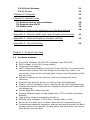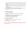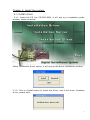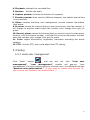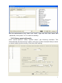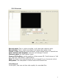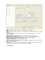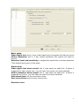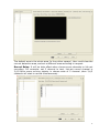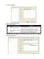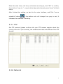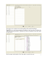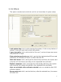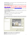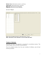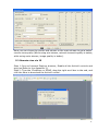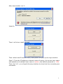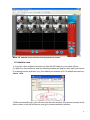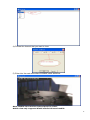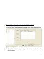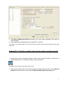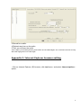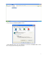
1
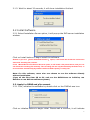
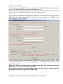
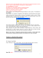
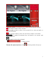
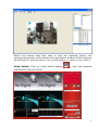
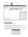
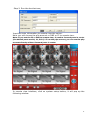
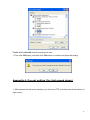
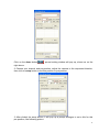
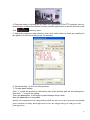
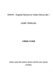
DNVR(Digital Network Video Recorder)
USER MANUAL
EG-6CP0S-4
EG-6CP0S-8
EG-6CP0S-16
EG-6CP1S-16
EG-6CP2S-32
Before using this system, please read the user manual
1
carefully.
Attention:
*Don’t use the system at place with high humility or dust or dirty.
*Avoid direct sunshine or being heated.
*Leave the system away from magnetism objects.
*Avoid high or low temperature(recommended temperature range: 5°C-35°C).
*Close the system before installing the hardware and software.
*Don’t place the system at some place where will likely have a shake.
*Please use it at the aeration place.
*Radio, television or wireless communicate device could cause damage to the
system.
*Don’t dismantle the system by yourself freely.
*Don’t put heavy object on the system.
Table of Content
Attention
2
Chapter 1. Product overview
3
1.1 Products features
1.2 Hardware requirement
1.3 Software requirement
3
4
4
Chapter 2. Install the system
2.1
2.2
2.3
2.4
Install driver
Install software
Apply for DDNS and p2p account
Channel number and draw mode selection
Chapter 3. Operate Main system
3.1 Log on system
3.2 Main screen of server
3.3 Setup
3.3.1 Local user management
3.3.2 Setup record with audio
3.3.3 Preview
3.3.4 Record
3.3.5 Alarm
3.3.6 Schedule
3.3.7 PTZ
3.3.8 Authorization(network user)
3.3.9 Others
5
5
6
6
7
9
9
9
11
11
12
13
13
14
17
18
18
20
2
3.3.10 Color Scheme
3.3.11 TV out
21
22
Chapter 4. Playback
22
Chapter 5. Remote view
25
5.1 Remote view by client software
5.2 Remote view via IE
5.3 Mobile view
25
27
28
Appendix 1. Auto login and auto run schedule setting
30
Appendix 2. Monitor audio and record audio synchronous
31
Appendix 3. Internet Explorer browser setting
33
Appendix 4. Pre-set setting
34
Chapter 1. Product overview
1.1
z
z
z
z
z
z
z
z
z
z
z
z
z
z
Products features
Run under Windows XP 32bit OS, Windows Vista 32bit OS;
6805 chipset 10-bit ADCs image quality;
Lightning-Proof design;
6805 chipset could display in real time or not real time, if you choose one
channel each chipset, then the display will be real time. And if you
choose two, three or four channels each chipset, then the display will be
not real time;
Adjust the setting for any channel, and can be applied to other
channels;
Snapshot the dynamic picture or static picture while playback;
Display, record, playback, control, backup can be done simultaneously;
Snapshot picture for single frame or snapshot picture for all frames while
live displaying;
Motion detection, alarm function;
Support different types of high speed dome, PTZ controller and alarm
decoder;
High quality network transmitting function;
Remote view, playback, PTZ control, through Wan or LAN;
Search by the date, time, location, alarm period, snapshot pictures;
Complete automatically operation: user can set record schedule for each
camera within all the periods of each week; and the system will record
according to the schedule;
3
z
z
z
z
z
1.2
z
z
z
z
z
z
1.3
z
z
z
User can set alarm activation schedule for each alarm sensor within all
the periods of each week, the alarm sensor will activate according to the
schedule;
User can set motion detection for each camera within all the periods of
each week, and the motion detection will activate according to the
schedule;
Circularly switch function; Can set single channel or multi channels to
switch circularly;
User-friendly interface, it is easy for user to operate it;
The system will show hard disk is full if the hard disk will up to the
capability.
Hardware requirement
RAM:512MB or above
Display card: ATI128MB or above,Geforce2 MX400 128MB or
above
CPU: Celeron D2.8 G or above or Intel P4 2.4 G or above
Resolution of monitor: 1024*768(32bits color)
HDD: IDE, SATA,SCSI, 80GB or above
Motherboard: Intel Chipset 865 or above
Software requirement
Windows 2000/Windows XP/Windows Vista 32bit OS
DirectX 9.0
The latest driver for display card
Attention: before installing the driver of display card, please install the driver of
motherboard; otherwise it will affect the function of display card and video
surveillance system
4
Chapter 2. Install the system
2.1 Install driver
2.1.1. Insert the CD into CD/DVD-ROM, it will pop up a installation guide
window, shown as below:
Select Installation Driver option, it will pop up the driver installation window:
2.1.2. Click on Install button to install the driver, and it will show: Installing
driver, please wait…
5
2.1.3. Wait for about 30 seconds, it will show installation finished:
2.2 Install Software
2.2.1 Select Installation Server option, it will pop up the DVR server installation
window:
Click on Install button to begin install the software.
Remark: If you tick “Install Video Board Driver” option, it will install the card driver at the same
time while installing the software.
If tick “Install Record File Protect Driver” option, it will install a file protect driver, and you can
not delete the recording file manually. The recording file can only be deleted by the delete tool, or
be overwritten automatically by software while the HDD capacity is nearly full.
Note: For this software, users also can choose to run the software directly
without installation.
(Copy all the files from CD to PC, and run the DVRInit.exe to initialize, run
DVR.exe to run DVR surveillance system.)
2.3. Apply for DDNS and p2p account
2.3.1 First, initialize the software by double click on the DVRInit.exe icon.
Click on initialize button to begin initial. Please wait a moment, it will indicate
6
initialize successfully.
If you want to delete DDNS account, please tick “Delete DDNS account” option,
then it will delete DDNS account at the same time.
If you want to delete p2p account, please tick “Delete p2p service account”
option, then it will delete p2p account at the same time.
2.2.2 After initialization completely double click on DVR.exe icon, and go to the
DDNS and p2p account application interface. You can apply for a DDNS and a
p2p account in this window.
Input a account name and password then click on apply button to apply. After
completely application, it will show application succeeded information on the
top of the window.
Note: If you do not want to use the DDNS or the p2p, you can pass it without
application by click on Next button directly.
If you want to apply for another DDNS account or p2p account, please initialize
the software first, then apply for another one.
Standard: Select the right Video Standard (PAL or NTSC).
7
Remark: This series cards adopt 6805 chipset, and one chipset can support 4 channels at max. So,
there are 4 options of Channels/Device. The default is 2 channels/Device.
Take a EG-6CP0S-4 for example,
the default is 2, so it will show 2 channels in software by default.
If you choose 1 here, it will show only 1 channel in software.
If choose 3, it will show 3 channels in software.
And if 4, it will show 4 channels in software
Video Quality: you could ajust it and get different video quality. The default is
the highest.
Draw Mode: For a better compatible with different motherboards and graphic
cards, we provide 5 draw modes to choose. The default mode is mode 1. After
selected mode 1, it will show a live video image in the right window. And it will
pop up a prompt window, show as below:
If the video quality is good, then click on “Yes” button, and go to next step.
If the video quality is not good or you want to try another mode, please click on
“No”, and it will alter to next mode automatically.
After selected the right Video Standard, channels/device, draw mode, and
watched the live video image, click yes to confirm, and click on finish to finish
these setting and enter into the DVR surveillance interface.
Note: If you want to change the channels/device number or draw mode after
finished these setting, please initialize the software first, then set again.
Chapter 3. Operate Main system
3.1 log on system
Click “DVR.exe” under sever folder, user will get following login window:
User ID: admin
8
Password: 1234
Press “OK” and login into the DVR surveillance system.
3.2 Main screen of server
1
System setup
Playback
Circular
i
Run schedule
Monitor
4
Other
: Screen split
Capture picture
4
: Lock/Unlock
4
: Exit
Note: When the button is selected, it will become red from grey.
2. System setup: click it, user can get following icon to set the preview, record,
alarm, schedule, PTZ, authorization, others as below picture
3. Run schedule: click it, the system will run according to the schedule
9
4. Playback: playback the recorded files
5. Monitor: Monitor the audio
6. Capture picture: it allows the function of snapshot
7. Circular preview: Auto scan for different channels, the default interval time
is five seconds.
8. Other: contains minimize, user management, remote connect information,
disk status.
9. Preview: choose the channel that you want to preview, click the number, it
will change to preview status when the number color change from grey to
green.
10. Record, alarm: choose the channel that you want to record or start alarm
function, click the channel number, it will start to record or start alarm function
when the number color change from grey to green
11. Color: adjust black/white, brightness, saturation according the actual
situation
12. PTZ: click the PTZ, user could adjust the PTZ setting.
3.3 Setup
3.3.1 Local user management
Click
“other”
button
,
and
get
tool
list,
click
“local
user
management”, ”user management” window will pop-up. ”user
management” is only for setting authority of server user, it is different from the
“Network user authorization “ (If user want to remote view through IE ,
user need to set “Network user authorization “)
10
Set the authorization first, then click “add”, type the new user name and
password, then press “ok” to save the setting.
3.3.2 Setup record with audio
Click “record options” under “system setup”, get following interface. Tick
“Record Audio Synchronously” option, and copy to other channels that you want
to record audio synchronously, then save the setting.
11
3.3.3 Preview
Record name: Tick it, while recording, it will show the channel name.
Record time: Tick it, while recording, it will show the system time.
X-axis, Y-axis: Adjust the shown position of the channel name or record time.
Color of time auto brighten: the color will change if record.
Channel name: set the channel name.
Camera ID Position: set the position of the camera ID. Could choose in ”left
top, right top ,left bottom ,right bottom”.
Font: the font of the channel name will be changed if you choose set a font.
Sharpness: The sharpness of record name and record time.
3.3.4 Record
In this part, user can set the video quality for recorded files.
12
CBR: Constant bitrate, select it, the bitrate will not change
VBR: Variable bitrate, select it, the bitrate will change according to actual
situation
Record quality: provide 6 levels of record quality (level 1-6), “best” is
recommended.
Record audio synchronously: record audio while recording video.
Self define video quality: user can define the video quality by himself
Packing interval for recording file: Set the packing interval.
Select storage disk: set the storage location.
Active denoise time range: set the time range to reduce noise, from 18:00 to
8:00 is recommended.
Net trans: set the network transmit quality, provide 5 levels (level 6-11) and
self define transmit frame rate. 5FPS is recommended.
3.3.5 Alarm
13
Basic setup
Video Signal lost: tick it, if any video signal lost, the system will start to record
Motion detection: tick it, if any motion detected, the system will start to
record
Detection level and sensitivity: to adjust the sensitivity of motion detection
(The default level super is the best)
Alarm relay:
Video signal lost alarm sound: tick it, and select an audio file. If alarm is
triggered by video signal lost, you will hear the sound you have selected
Motion detection alarm sound: tick it, and select an audio file. If alarm is
triggered by motion, you will hear the sound you have selected
Post-alarm time: set the post-alarm time.
Post-record time: set the post-record time.
Detection area
14
The default area is the whole area (in the yellow square). User could clear the
current detection area, and set a different area according to request.
Record Relay: It will be take effect when choose some channels to link-act
recording. For example: set 5 channel to test, link-act record channel is
3,4,5.Once some moving objects in choose area of 5 channel ,then 3,4,5
channels will start to record simultaneously .
15
3.3.6 Schedule
Set the record schedule here.
Basic working mode
S/N Basically work model
1
Record
2
Motion Signal detect
Remark
Continual record.
If any motion detected, the record will be
triggered, and system begin to record.
3
Record &Motion signal If any motion detected, the record will be
detection
triggered, and system begin to record.
If no motion, it is continual record.
How to set: choose channel (for example: channel 1) and date (for example:
Monday), select the default record in the table and click “Edit”, user will get
following information:
16
Enter the start time, end time, and select record type, click “OK” to confirm,
then click on “copy to..” , copy to other days and channels, press “save” to finish
setup.
After finished the setting, go back to the main interface, and Click “run on
schedule” button(
), the button color will change from grey to red, it
indicates the schedule is working.
3.3.7 PTZ
Set PTZ protocol (please confirm with your PTZ camera supplier about the
correct protocol of your camera), the suitable baud rate and address of the PTZ
decode.
3.3.8 Network
17
This option is for network user authorization and trusted IP address.
Trust IP: user could setup accessing IP address, limit accessing IP address by
[add network user][modify IP ] [delete IP], tick the IP address if user don’t want
to limit the IP
Set the proper authorization first, then add or modify the user.
18
3.3.9 Others
This option includes tools which do not list on the toolbar of system setup.
Lock system key: tick it, while running the system, if click on any button of
system, it can not work until unlock the system.
Logon manually: tick it, while click the” dvr.exe”, use has to type user name
and password to logon
Enter windows and auto run: tick it, and set the right windows OS user and
password, the software will auto run after start the PC.
Auto shut down: tick it, and type the interval day and time, the system and
computer will shut down according to the requested time and date
Restart computer: tick it, and type the interval day and time, the system
and computer will restart according to the requested time and date.
Auto run schedule after software started: auto run schedule after DVR
software started.
Mouse auto lock: tick it, and set the time, after the selected time, the mouse
will auto lock.
19
Net trans port: if user allows other user to remote access this server, must
tick it, the default port is 5191.
Web Server port: if user allows other user to remote access this server, must
tick it, the default port is 80.
Remark: If user the default port, while other user remote access the
server, just type the IP address of server, for example:
http://192.168.5.2 . Once user change the default Web Sever port
from 80 to 81, then has to type http://192.168.5.2:81 .
FTP server port: if user allows other user to remote access this server, must
tick it, the default port is 21.
Push warn dialog when disk full: tick it, while the disk is nearly full, it will
have a warn dialog.
DDNS: the secondly domain name in viewnvr.com you applied.
P2P account: the p2p account you applied in software.
3.3.10 Color Scheme
In some area, because of the big change of the lights, the video quality from
camera will change accordingly. To get the better video quality, color scheme is
useful.
Start time: choose the begin time for the adjusted color
End time: choose the finish time for the adjusted color
Edit time: make change for above set time
20
Delete time: delete above start or end time
Clear time: clear above start, end time
Start all: start all the time selected
Close all: close all the time selected
3.3.11 TVout
Select the channel and set the interval time to TV out.
Note: the max TV out channel is 16 for each the card.
Chapter 4 Playback
Recorded file search and playback is important for surveillance system. This
system adopts video and audio synchronization
Press the playback button from the main interface of software, user will get
following interface:
21
Calendar system: The different color of date indicate different situation
The number of date is white: No date
The number of date is yellow: has recorded file for video and audio, or
pictures information
The number of date is yellow color and with an ellipse: Current date
: To adjust the playback time. Left button is for minute; right
button is for hour.
: Snapshot picture when playback
7
: To adjust volume
Browse the captured picture: click
, following window will pop up:
22
Select the channel that user want to view the captured picture, the
corresponding picture will be listed at the right bottom window. Click the picture
file and open it, user can zoom in or out the picture, or save it on pc, print it.
Mode Switch: Click on mode switch button(
), then the playback
interface will show as follow:
23
Here you can open a file to play or backup the recorded file.
Burn: click on burn button(
),
then it will show the burn window:
Here you can burn the recorded file to CD.
Chapter 5: Remote view
5.1 Remote view by client software
With the client program, user can remote view the live picture from server, and,
record, playback the recorded file from server or local PC.
Step 1: Insert the CD into the CD/DVD-ROM, it will pop up the software
installation window, select the Installation client option, click on Install button
to install the client software.
24
Step 2: Run the dvrcliect.exe,
Input the login information to remote view the server.
Here you can choose the p2p account or DNS or IP to remote view.
Note: If you use the IP or DNS to remote view, it need to forward ports in router
(the default ports are 80, 21, 5191). If use the p2p account, you can use the p2p
account directly without forward ports in router.
In remote view interface, click on system setup button, it will pop up the
following window:
25
Here you can choose to use the sub-stream or the main-stream to get a better
remote view quality (While using sub-stream, network transmit quality is better;
while using main-stream, image quality is better).
5.2 Remote view via IE
Step 1: Run an Internet Explorer browser, Enable all the ActiveX controls and
plug-ins(Refer to the Appendix 3).
Step 2: Type the IP address or DDNS, drag the right scroll bar to the end, and
click the here to download the ActiveX control.
26
After downloaded, run it:
Install it:
Then it will show install succeed.
Then refresh the IE browser once, and system will pop-up the login window:
Step 3: Type the IP address or domain name of server, the correct user name
and password, the default user name is: admin; the default password is: 1234.
Then click “ok”, you will get following interface to show that the connecting are
successful.
27
Note: IE remote view need to forward ports in router.
5.3 Mobile view
1). Copy the client software dvrclient.exe from WinCE folder to your mobile phone.
2). Open the client software, and the following window will pop-up, then input your server
IP or domain name, and user, key. (Our default port number is 5191) default user and key:
admin, 1234.
3).After successfully login, you will enter into the main window, then choose camera at the
menu (menu on the top left corner) and go to channel selection window.
28
4).Choose the channel that you want to view:
5). Enter into the main surveillance window, show as below:
Note: Mobile view need to forward ports in router.
Mobile view only supports WinCE mobile OS based mobile.
29
Appendix 1. Auto login and auto run schedule setting
1. Enter into system setup interface, select schedule option, and set the schedule here:
2. Copy the schedule to other days.
3. Copy the schedule to other channels.
4. Select other option, and tick auto run schedule after software started option to let it
auto run schedule:
30
5. Tick Enter windows and Auto run option, let it auto login computer’s OS, and run
DVR software.
6. Input username and password, and restart PC to check it.
Note: Here are the windows OS user and password. Please input the right username and password to login
window OS.
Appendix 2. Monitor audio and record audio synchronously
1. Monitor the audio in preview interface: Click on the channel’s picture, then click on
monitor button once, it will become blue, shown as below:
Note: Make sure you can hear the audio while preview.
2. Click system setup button, enter into the system setup interface, then choose Record
Options, select channel name, and tick Record Audio synchronously option.
31
3.Record for a while.
4.Playback and turn on the audio.
5.Then you will hear the audio.
Notes: Before you do audio function, please make sure the audio adapter can work and connected correctly.
One audio input point to one video input.
Appendix 3. Internet Explorer browser setting
1. Run an Internet Explorer (IE) browser, click tool menu, and select Internet options…
option:
32
2. Then it will pop up Internet options window:
3. Select Security option, and click Internet icon, and click on Custom Level… button,
then it will pop up the following setting window:
33
Enable all the ActiveX controls and plug-ins here.
4. Then click OK button, and then click Yes button to confirm and save the setting.
Appendix 4. Pre-set setting (for high speed dome)
1. After entered into the main interface, you will see a PTZ controller area at the bottom of
right corner:
34
Click on the dome button(
), pre-set setting window will pop up, shown as on the
right above.
2. Choose your channel and pre-position, adjust the camera to the requested direction,
then click on setup button to set this position to pre-position:
3. After clicked the setup button, it will pop up a prompt dialogue to set a title for this
pre-position, like following picture.
35
4. Enter the name by clicking the up, down, left, right button of the PTZ controller (use up,
down buttons to select the number or letter, use left, right buttons to set the direction), and
click
button to save.
5. Adjust the camera to other direction, then click “use” button to check your setting for
pre-position (It will turn to the pre-set 1’s direction).
6. Follow the step 1 to 6 to set other pre-sets.
7. Pre-sets patrol setting:
Click “+” to add the pre-sets to the bottom part of this window, and set the holding time,
then click “√” to save the setting.
Then tick start option, it will begin to patrol between the pre-sets.
Non-tick start option to stop patrol.
Remark: above information will be changed timely without any notice. If user has any questions and problem,
please come back to us timely. We will offer the best service .We will appreciate if you could give us some
good suggestions!
36