1
International Journal of Emerging Technology and Advanced Engineering
Website: www.ijetae.com (ISSN 2250-2459, ISO 9001:2008 Certified Journal, Volume 3, Issue 11, November 2013)
IV. DESIGN & SIMULATION
Model based design approach is an ideal approach for
Embedded System Design. There are many system model
tools available from various vendors. These tools facilitate
the design of hardware and software before actual physical
implementation of the system. Proteus tool is used for this
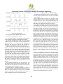
project. The Protues tool also provides virtual instruments
like Oscilloscope, Logic analyser to monitor the signals of
the system. Students install and learn the use of the Proteus
tool by going through the readymade examples which
comes free with the tool. Step by step design process of
building a small system for example flashing, counting,
shifting, and rotating a set of LEDs connected to 8051
Microcontroller ports is designed and practiced using the
assembly language programming and drawing the schematic
of the system. Proteus allows assembly code to be
assembled and downloaded on the virtual 8051. For C
language coding Keil compiler can be used and the
generated hex code can be used to configure and run the
virtual 8051.
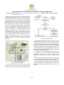
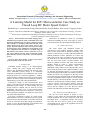
Fig:5 Closed Loop Flow Chart
The firmware flow chart is shown in Fig- 5. In every
embedded system design first step is to initialize all the
elements in the project. Here LCD, keypad, timer, LED, ref
speed is initialized. Device driver for Keypad, LCD display,
Motor speed sampler and firmware modules for Speed Error
comparator, Up/Dn counter, PWM signal generator are
coded, assembled and debugged individually. In next step
these modules are integrated for uniform flow of control and
data across all modules in real time.
The keypad User Interface Module (UIM) provides the
user facility to view and/or change all the control and
monitoring variables with control program. After
initializations processor waits for any key pressed by the
user.
The speed error difference between the set speed and
actual speed controls the duty cycle of PWM signal. If there
is speed error the previous PWM duty cycle is maintained.
The closed loop system samples the motor actual speed,
computes the speed error, changes the Up/Dn counter value
and finally regulates the PWM duty cycle every 1 sec
interval.
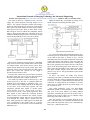
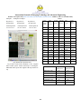
Fig:4 Proteus Circuit Simulation
The 8051 microcontroller based closed loop DC motor
control system as shown in Fig-4. The system is equipped
with an LCD display, a keypad, transistorized motor driver.
383