1
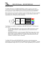
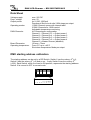
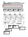
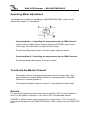
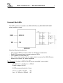
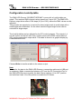
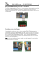
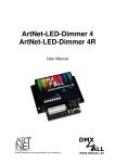
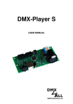
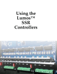
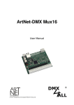
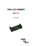
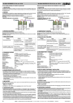
DMX-LED-Dimmer
BIG BROTHER MK2
330mA – 1500mA
User Manual
DMX-LED-Dimmer – BIG BROTHER MK2
2
Specification
The DMX-LED-Dimmer „BIG BROTHER MK2“ includes 4 outputs, which has a
current soure from 0 up to 350mA/700mA/1400mA. The DMX software can control
the output power. Another DMX Channel can be added and driven as MASTER.
Each output driver comes with a resolution control of 1024 steps; this driver regulates
the output power. The custom made driver allows a constant power, which is not
modulated by the PWM (pulse width modulation).
DMX
* = auch in 700mA /
DMX
INTERFACE
RISC
CONTROLLER
0-350mA*
R
0-350mA*
G
0-350mA*
B
0-350mA*
W
1000mA / 1400mA
Two Modes are available for handling the „BIG BROTHER MK2“ in 1024 steps on
each output:
-
The „BIG BROTHER MK2“ can be driven with 2 DMX-Channels per output.
The first channel allows a coarse adjustment and the second one a fine
adjustment.
-
„BIG BROTHER MK2“ can be driven with 1 DMX-Channel per output. In this
Mode a table is used to assign the 256 DMX-values to the 1024 steps. The
table can be created by a PC-Tool. To transfer these DMX-values into the
interface a connection cable is necessary.
The DMX-LED-Dimmer BIG BROTHER MK2 includes an optimal temperature
monitoring to control the added LEDs by a temperature sensor. (Equipment. The shut
down temperature range from 0°C up to 120°C can be regulated by a PC connection.
DMX-LED-Dimmer – BIG BROTHER MK2
3
Data Sheet
Voltage supply:
Drop- voltage:
Output power:
Operating modes:
DMX-Channels:
Board Dimension:
Operating temperature:
max. 26V DC
max. 2V
4x 0-(330..1500)mA
Permanent Short-circuit safe/ 1024 steps per output
1 DMX-Channel comes with internal table
2 DMX-Channels for 10-Bit control
Adjustable temperature monitoring
4-8 Channels per configuration
Channel 1 / Channel 1+2 = Output power 1
Channel 2 / Channel 3+4 = Output power 2
Channel 3 / Channel 5+6 = Output power 3
Channel 4 / Channel 7+8 = Output power 4
Channel 5 = Master Dimmer (disabled)
121mm x 73mm
From 0°C up to +45°C
Shut down temperature Mode per output
DMX starting address calibration
The starting address can be set by a DIP-Switch. Switch 1 has the valency 20 (=1),
Switch 2 has the valency 21 (=2) and so on… finally Switch 9 has the valency 28
(=256). Each Switch, which is moved to ON position, represents the starting address.
Switch 10 is moved to OFF in normal mode.
On
2
3
4
5
6
7
8
9 10
1
2
4
8
16
32
64
128
256
1
DMX-LED-Dimmer – BIG BROTHER MK2
Connecting terminals
Warning:
Do not connect an output- or input- connector among each other!!!
LED output1
1 – LED+ (orange)
2 – LED- (blue)
LED output2
1 – LED+ (orange)
2 – LED- (blue)
DMX-input
1 – GND
2 – DMX3 – DMX+
voltage supply
1 – 7-26V DC (orange)
2 – GND
(blue)
AAI
Input Connection to
combine more
Interfaces
LED output3
1 – LED+ (orange)
2 – LED- (blue)
PC-Control
Connecting cable for
PC
(not included)
LED output4
1 – LED+ (orange)
2 – LED- (blue)
AAO
Output Connection to
combine more
Interfaces
4
DMX-LED-Dimmer – BIG BROTHER MK2
5
Operating Mode adjustment:
Two Modes are available for handling the „BIG BROTHER MK2“, which can be
adjusted by Jumper 1 (red marked):
-
Operating Mode 1: Controlling the output power by one DMX-Channel.
In this mode a LookUp-table is used to assign the 256 DMX-values to the
1024 steps. The table can be created for each output.
For this operating mode jumper J2 must be open. (delivery status)
-
Operating Mode 2: Controlling the output power by two DMX-Channels.
For this operating mode jumper J2 must be closed.
To activate the Master Channel
The master channel is used as a brightness control for each output. This
Master Channel occupies DMX-Channel 5 in operating Mode 1 and DMXChannel 9 in operating Mode 2.
To activate the Master Channel Jumper J1 (red marked) must be closed.
Service
For service the outputs can be permanently turned ON or OFF by moving switch 5
and 10 to ON position. Switches 1-4 turn ON or OFF the dedicated outputs.
A RESET to delivery status can be executed by moving switch 1,3,5,7,9 and 10 to
ON position and power up the DMX-LED-Dimmer. After a reset is done the DMX-LED
blink.
DMX-LED-Dimmer – BIG BROTHER MK2
Connect the LEDs
The LEDs can be connected to the DMX-LED-Dimmer „BIG BROTHER MK2“
serial, parallel or mixed.
Note the following introductions:
-
Only connect LED`s to output, which are identical in construction.
Each LED line must have an equal number of LEDs.
UGES is about 2V lower than UIN.
IGES = ΣILED must comply with the output electric current of the DMX-Dimmer,
because the outputs are power regulated.
For Example: 24 white LUXEON 1W LED`s are connected to one output.
LED-data: ULED = 3,42V; ILED = 350mA
Supply voltage: 24V DC
6 LEDs connected serial to 4 lines.
UGES = 6 * 3,42V = 20,52V
IGES = 4 * 350mA = 1400mA
OK
OK
6
DMX-LED-Dimmer – BIG BROTHER MK2
Examples for different ways of connecting LEDs
Example 1:
If a series connection is used every LED get the same operating power. The voltage
of all LEDs is about 2V lower than the operating voltage.
Example 2:
If a parallel connection is used the operation power splits into equal parts to supply
each LED. The power of all LEDs must comply with the input power.
7
DMX-LED-Dimmer – BIG BROTHER MK2
Color Change
Color Change can be used by moving Switch 10 to ON position. Use Switch 1-3 to
choose a default color change setting.
Jumpers 4-9 = OFF / 10 = ON
Jumpers 1-3: color change setting
Following default color change settings are available:
color change 1:
color change 2:
color change 3:
color change 4:
color change 5:
color change 6:
color change 7:
color change 8:
8
DMX-LED-Dimmer – BIG BROTHER MK2
9
User-defined color change
The DMX-LED-Dimmer “BIG BROTHER MK2” provides an option to program up
to 16 color changes by using an EERPOM. This only can be used if an EEPROM
Type 24C64, 24C128 or 24C256 is installed at IC-socket. Switch 1-4 offers a
menu selection for light samples. Move switches 5-9 to OFF and switch 10 to ON
position to use a user-defined color change.
Jumpers 5-9 = OFF / 10 = ON
Jumpers 1-4: color change setting
Create a color change diagram
The software “DMX-Configurator” is needed to create a color change diagram.
The adjustable DMX-Channels 1-4 are dedicated to outputs 1-4. The allocation of
a color change diagram to a chosen light sample is analog. So the first diagram is
equivalent to the first light sample. (All switches are moved to OFF position).
Creating a light sample see user manual “DMX-Configurator”
Note:
The indicated time unit of the adjusted light sample could been different from
replay, it is only a standard value.
A program file for the EEPROM can be created under File→Export HEX-Data for
a favourite light sample, this file can be written to the EEPROM by a usual
programmable device.
DMX-LED-Dimmer – BIG BROTHER MK2
10
LED-Display-Codes
The integrated DMX-LED is used as a multifunctional display.
This LED lights nonstop in normal operation. If the LED does not light, there is no
DMX512-input-signal.
Also the LED signalled the operation status. In this case the LED lights up in short
pitches and then turns into off modus. The Number of flashing signals is equal to the
Number of the error status.
Error
Status
2
Error
Description
Address error
Check if a valid DMX- starting address is adjusted at
the DIP-switch.
An invalid DMX input signal is established, invert the
signal line by changing switch 2 and 3. Or use a
twisted pair wire.
3
DMX-signal error
4
Temperature error
Dimensions:
All details in mm
- No temperature sensor is found although the
temperature monitoring is enabled.
- The adjusted temperature is out of range.
DMX-LED-Dimmer – BIG BROTHER MK2
11
Configuration LookUp-table
The DMX-LED-Dimmer “BIG BROTHER MK2” comes with a LookUp-table per
output. The received DMX-channel values goes from 0 up to 255. The DMX-LEDDimmer output driver offers 1024 steps (0 up to 1023), where the DMX values can be
adjusted.
This provides an opportunity to control the lower bright levels in small steps with a
small brightness modulation. On the other hand the higher bright levels can be
controlled in larger steps.
The LookUp-tables can be adjusted by the PC-control-program. The outputs 1-4
can be chosen on the left side. Every output comes with a DMX values table (0255) and the appendant output value. This table is shown in a graphic display by
a characteristic curve.
Choose Write to transfer a table to the shown output.
Note:
To transfer the data to the DMX-LED-Dimmer a connection cable and a USB port
is necessary. Make a connection between a PC and the PC-Connection-Port of
the DMX-LED-Dimmer to transfer the data. Move switches 1-8 to OFF position
and switches 9 and 10 to ON position to enable the PC-Mode.
WARNING: During the PC-Mode the DMX signal must cut off !
DMX-LED-Dimmer – BIG BROTHER MK2
12
External DMX starting address calibration
The DMX- address module can adjust an external starting address, which is available
as equipment. This DMX-address module can be connected to the DMX-LEDDimmer by the Extension-Port, which connects all data lines with each other and the
voltage supply.
Combine more Interfaces
If an application needs more than 4 outputs, another DMX-LED-Dimmer can be
combined by a connection cable between the AAO output (first DMX–LED-Dimmer)
and the AAI input (second DMX-LED-Dimmer). The added outputs will be accessed
by the following DMX-Channels automatically. To set a starting address is only
necessary for the first DMX-LED-Dimmer. Any other connected DMX-LED-Dimmer
must have the starting address 1.
Note: In this case the Master-channel can be controlled separate for any interface
instead of controlling all outputs.
DMX-LED-Dimmer – BIG BROTHER MK2
13
CE-conformity
This assembly (board) is controlled by a microprocessor and
uses high frequency (8MHz). To get the characteristics of the
assembly in relation to the CE-conformity, an installation in a
compact metal casing is necessary.
Risk-Notes
You purchased a technical product. Conformable to the best available technology the
following risks should not excluded:
Failure risk: The device can drop out partially or completely at any time without
warning. To reduce the probability of a failure a redundant system structure is
necessary.
Initiation risk: For the installation of the board, the board must be connected and
adjusted to foreign components according to the device paperwork. This work can
only be done by qualified personnel, which read the full device paperwork and
understand it.
Operating risk: The Change or the operation under special conditions of the
installed systems/components could as well as hidden defects cause to breakdown
within the running time.
Misusage risk: Any nonstandard use could cause incalculable risks and is not
allowed.
Warning: It is not allowed to use the device in an operation, where the safety of
persons depend on this device.
DMX4ALL GmbH
Sophienstr. 8
D-44791 Bochum
Germany
© Copyright 2009 DMX4ALL GmbH
All rights reserve. No part of this manual may be reproduced in any form (photocopy, pressure,
microfilm or in another procedure) without written permission or processed, multiplied or spread using
electronic systems.
All information contained in this manual was arranged with largest care and after best knowledge.
Nevertheless errors are to be excluded not completely. For this reason I see myself compelled to
point out that I can take over neither a warranty nor the legal responsibility or any adhesion for
consequences, which decrease/go back to incorrect data. This document does not contain assured
characteristics. The guidance and the characteristics can be changed at any time and without
previous announcement.