1
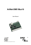
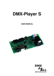
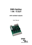
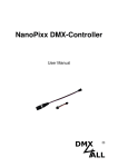
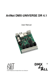
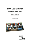
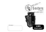
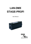
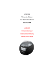
DMX-Player L
User Manual
DMX-Player L
2
Description
The DMX-Player L is a DMX-StandAlone device. The scenes provided in the PC can
be loaded by USB on the device. Without PC the deposited scenes will be
reproduced. The selection of the Scene can occur in different way. An application in
the live operation with connected PC is as possible.
Due to the easy handling the application is possible in decoration and presentation
sections.
IR INPUT
IR
DECODER
POWER
CONTROL
RESET
RTC
SWITCH
CONTROL
PROGRAM
CONTROL
MEMORY
RISC
CONTROLLER
DIGITAL
INPUT
DIGITAL
CONTROL
DMX
INTERFACE
DMX-OUT
LED-DIMMER*
LED-OUT
Energy Saving Design:
By modern switch-power-supply-technology it will be generated less warmth
considerably and therefore the energy consumption is lowered.
Data Sheet
Voltage supply:
7-24V DC / 250mA (Without LED-Dimmer BABY)
DMX-OUT:
channels
Internal clock (RTC)
Digital control-input for control per button
Program-Trigger up to 16 Timer possible
Brightness-control per UP/DOWN button, Poti or IR
Playback rate per UP/DOWN button, Poti or IR
scenes Selection:
first 10 per button
first 16 per button-Matrix 4x4
first 25 per button-Matrix 5x5
up to 250 scenes per numerical keypad with ENTER and BLACKOUT
first 10 per RC5 IR-remote control
- USB-Connection to transfer of the scenes or as a PC DMX-Interface in the live
operation
- 8Kbyte Stand-Alone-Memory (up to 32kByte with 24C256 possible)
- DMX-LED-Dimmer BABY slip-on
Board-dimensions:
64,2mm x 82mm
DMX-Player L
Installation USB
The Interface installation happens in two parts.
Part 1: Installation the USB-driver
- Put the DMX interface to a free USB port of your PC.
There appears the announce-ment
which was found new hardware.
- Follow the hardware assistant and select for the drivers source Other Source
specify and afterwards the place for the driver
- Certify the located driver with Next and complete the driver’s installation with
Finish/Complete.
Part 2: Installation Vitrual COM-Port
- After the installation of the USB driver a USB-Serial-Port will be automatically
identify.
There also appears the announcement new hardware was found.
-
Follow the hardware assistant and select for the drivers source Other Source
specify and afterwards the place for the driver
-
Certify the located driver with Next and complete the driver’s installation with
Finish/Complete.
The installation can differ according to the used operating system and driver's
version.
The newest driver you can find on our hompage
www.dmx4all.de
3
DMX-Player L
4
Connections
Voltage supply
GND
- 0V
V+
- + 7 - 24V DC
DIG IN - Control Input
LED-Display
Connection
GND
DMXDMX+
RED
- POWER OK
GREEN - DMX OK
USB Connection
TWI-Interface
SCL
NC
NC
GND
1
+5V
SDA
Scenememory
EEPROM 8k (24C64)
(Standard)
EEPROM 32k /24C256)
LED-Dimmer
Expandability
for DMX-LED-Dimmer BABY
which is available as
equipment
Control-Access
1
2
3
4
5
6
7
8
9
10
- PRG1
- PRG2
- PRG3
- PRG4
- PRG5
- PRG6
- PRG7
- PRG8
- PRG9
- PRG10
11
12
13
14
15
16
17
18
19
20
- SPD+
- SPD- INTENS+
- INTENS- PRG+
- IR
- SCL
- SDA
- GND
- +5V
For wiring see the following
pages
DMX-Player L
5
Program selection
The selection of the deposited scenes can be effected with different wirings. Which
wiring is used, must be configured in the Setup-Menu or the DMX-Configurator (For
this see the part Configuration).
The last selected scene will be recorded and after re-starting automatically
launched.
►See „Running one scene after power on“
Selection per 10 button
The first 10 stored scenes can be called directly about up to 10 buttons.
Connection:
PRG1
PRG2
1
PRG3
2
PRG10
3
10
GND
Selection about Button-Matrix 4x4 or 5x5
With a Matrix-wiring it is possible to call up to 25 Programs per one button.
Connection Matrix 4x4:
PRG1
PRG2
PRG3
PRG4
1
2
3
4
5
6
7
8
9
10
11
12
13
14
15
16
PRG5
PRG6
PRG7
PRG8
DMX-Player L
6
Connection Matrix 5x5:
PRG1
PRG2
PRG3
PRG4
PRG5
1
2
3
4
5
6
7
8
9
10
11
12
13
14
15
16
17
18
19
20
21
22
23
24
25
PRG6
PRG7
PRG8
PRG9
PRG10
Selection about numeric keypad with ENTER and BLACKOUT
The input of the executive Scene happens with the numeric keypad and next ENTER.
The programs 1 up to 250 are possible.
In addition, with the switch BLACKOUT the blackout function can be switched-on and
switched-off with the key. The button ENTER automatically switches off the blackout
function.
Exampel:
Scene 28: ‚2’ + ‚8’ + ‚ENTER’
Scene 146: ‚1’ + ‚4’ + ‚6’ + ‚ENTER’
Connection:
PRG1
PRG2
PRG3
1
2
3
4
5
6
7
8
9
0
ENTER
PRG4
PRG5
PRG6
BLACK
OUT
PRG7
Selection about 8-Bit-BCD Signal
With a BCD control-signal up to 250 Scenes can be called. Therefore the 8 bits of the
BCD signal to the entrances PRG1 to PRG8 have to be established.
DMX-Player L
7
Brightness Setting
The brightness setting can be carried out per UP/DOWN button or Potentiometer.
INTENS+
INTENS-
+
-
+5V
INTENS+
10k
GND
GND
Wiring with UP/DOWN button
INTENS-
Wiring with Potentiometer
During the operation the brightness value will be saved with the UP/DOWNbutton and retained during shutdown the DMX-Player L.
Speed Setting
The speed setting can be carried out per UP/DOWN button or Potentiometer.
SPD+
SPD-
+
-
GND
Wiring with UP/DOWN button
+5V
SPD+
10k
GND
SPD-
Wiring with Potentiometer
During the operation the speed value will be saved with the UP/DOWN-button and
retained during shutdown the DMX-Player L.
DMX-Player L
8
Program StandAlone-function
The DMX-Player L has a user programmable StandAlone-function. The Scenes
arranged in the PC (programmes) will be transferred once to the interface and then
can be replayed.
The software DMX-Configurator serves for the production and programming of the
scenes. Under the menu point Settings→Communication settings the interface above
which the DMX-Configurator finds the connected hardware will be set.
TimerSetting
Step-admin
Scenes-admin
In the left part there is the scenes admin. Here the scenes can be set up and fixed in
the order.
The right part shows the step admin. Every Scene exists of one step at least. For the
setting of different DMX values there are controller available. These are marked with
the channel number. To reach all 512 DMX channels, you must select the DMX
channel area with the underneath horizontal racketeer. For every step different DMXvalues can be set for every channel.
Furthermore for every step the fade time and residence time will be set with Fade
Time and Wait Time.
You can write the provided scenes in the Stand-Alone-memory of the DMX player
"S". The transfer of the scenes to the interface can be started under
Hardware→Write data.
Attention: This process can last some time! Please, do not break off the transfer and
wait for certification of the DMX-Configurators.
DMX-Player L
Executing a Scene after starting
After starting a specific scene can be replayed. For this, by compilating the scene in
the DMX-Configurator the Default Scene on Start have to be denoted. If this is
denoted, the selected scene under Default Scene on Start will be achieved by
starting the DMX-Player L.
Configuring the DMX-Player L
The DMX-Player L can be configured about the DMX-Configurator from the version
1.5. Select therefore Settings→Hardware settings by connected DMX-Player L. It
appears the following dialogue:
The first 6 selection fields fix
the connected button
configuration. Only one
choice is possible
Fade between Scenes
allows fading between
scenes
Fill DMX outputs 512 DMXchannels, from channel 193
with the value 0.
Configurating the used
remote control: RC5 remote
or DMX4ALL LED
Configurating the DIG IN
control input
The configuration is transferred and stored by OK to the DMX player L.
9
DMX-Player L
10
Internal Clock (RTC)
The DMX player L disposes of an internal clock with which scenes can be start at
adjustable times.
Time setting
Select in the DMX-Configurator
Hardware→Syncronize Clock .
Now the topical PC-PC-system-time will
transferred on the DMX player L.
Digital Input Control DIG IN
The digital Input Control DIG-IN of the DMX-Player L can be configurated as follows:
(see DMX-Player L configurating)
-
Process next program
Switch On/AOFF
ON/OFF (short activity)
and brightness setting (long activity)
Process next program (short activity)
and brightness setting (long activity)
Process „Default scene on start”
The wiring of the Input control will be carried out as shown in the following view:
DIG IN
GND
V+
7-24V
GND
DMX-Player L
DMX-Player L
IR-Operation
The DMX player L allows an IR-Operation by means of external IR-Sensor. An IRSensor is connected to the Pin 16 of the Control connection.
The stored scenes can be called by IR-remote control.
The DMX player L can be used by DMX4ALL LED remote control.
Operating with DMX4ALL LED-remote control
The program selection happens about the keys 1,2,3 ... 9,0 according to the
programs from the 1 up to 9. The key 0 is for a free colour setting.
About the keys + and – the brightness and the speed is adjustable as well as is
possible for a program selection.
After actuating the key SPEED, the speed is adjustable;
After actuating the key PROG SELECT, the programs are selectable;
After actuating the key R, G or B, the brightness is adjustable.
A separate setting for Red, Green and Blue is not
possible.
The switch BLACK OUT activates and deactivates
the BlackOut-function. Besides the brightness
setting will be persist.
The switch FLASH activates and deactivates the
Flash-function, which engaging all Channels on
100%. Besides the brightness setting will be
persist.
11
DMX-Player L
12
CE-conformity
This assembly (board) is controlled by a microprocessor and
uses high frequency (8MHz). To get the characteristics of the
assembly in relation to the CE-conformity, an installation in a
compact metal casing is necessary.
Risk-Notes
You purchased a technical product. Conformable to the best available technology the
following risks should not excluded:
Failure risk: The device can drop out partially or completely at any time without
warning. To reduce the probability of a failure a redundant system structure is
necessary.
Initiation risk: For the installation of the board, the board must be connected and
adjusted to foreign components according to the device paperwork. This work can
only be done by qualified personnel, which read the full device paperwork and
understand it.
Operating risk: The Change or the operation under special conditions of the
installed systems/components could as well as hidden defects cause to breakdown
within the running time.
Misusage risk: Any nonstandard use could cause incalculable risks and is not
allowed.
Warning: It is not allowed to use the device in an operation, where the safety of
persons depend on this device.
DMX4ALL GmbH
Reiterweg 2A
D-44869 Bochum
Germany
© Copyright 2013 DMX4ALL GmbH
All rights reserve. No part of this manual may be reproduced in any form (photocopy, pressure, microfilm or in another
procedure) without written permission or processed, multiplied or spread using electronic systems.
All information contained in this manual was arranged with largest care and after best knowledge. Nevertheless errors are to be
excluded not completely. For this reason I see myself compelled to point out that I can take over neither a warranty nor the legal
responsibility or any adhesion for consequences, which decrease/go back to incorrect data. This document does not contain
assured characteristics. The guidance and the characteristics can be changed at any time and without previous announcement.