1
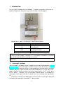
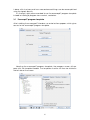
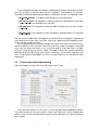
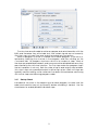
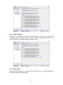
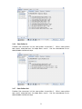
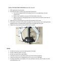
CB2
Euromap67 Manual
March 2011
1
Contents
1 Introduction
1.1 Euromap67 standard . . . . . . . . . . . . . . . . . . . . . . . . . . . . .
1.2 CE . . . . . . . . . . . . . . . . . . . . . . . . . . . . . . . . . . . . . . . .
3
3
4
2 Robot and IMM integration
2.1 Emergency stop and safeguard stop .
2.2 Connecting a MAF light guard . . . . .
2.3 Mounting the robot and tool . . . . . .
2.4 Using the robot without an IMM . . . .
2.5 Euromap12 to euromap67 conversion
.
.
.
.
.
.
.
.
.
.
.
.
.
.
.
.
.
.
.
.
.
.
.
.
.
.
.
.
.
.
.
.
.
.
.
.
.
.
.
.
.
.
.
.
.
.
.
.
.
.
.
.
.
.
.
.
.
.
.
.
.
.
.
.
.
.
.
.
.
.
.
.
.
.
.
.
.
.
.
.
.
.
.
.
.
.
.
.
.
.
4
4
4
5
5
5
3 GUI
3.1 Euromap67 program template . .
3.2 I/O overview and troubleshooting
3.2.1 Control . . . . . . . . . . . .
3.2.2 Manufacturer dependent
3.2.3 Safety . . . . . . . . . . . . .
3.2.4 Status . . . . . . . . . . . . .
3.3 Program structure functionality . .
3.3.1 Startup Check . . . . . . . .
3.3.2 Free to Mould . . . . . . . .
3.3.3 Wait for Item . . . . . . . . .
3.3.4 Ejector Forward . . . . . . .
3.3.5 Ejector Back . . . . . . . . .
3.3.6 Core Pullers In . . . . . . . .
3.3.7 Core Pullers Out . . . . . . .
3.4 I/O action and wait . . . . . . . .
.
.
.
.
.
.
.
.
.
.
.
.
.
.
.
.
.
.
.
.
.
.
.
.
.
.
.
.
.
.
.
.
.
.
.
.
.
.
.
.
.
.
.
.
.
.
.
.
.
.
.
.
.
.
.
.
.
.
.
.
.
.
.
.
.
.
.
.
.
.
.
.
.
.
.
.
.
.
.
.
.
.
.
.
.
.
.
.
.
.
.
.
.
.
.
.
.
.
.
.
.
.
.
.
.
.
.
.
.
.
.
.
.
.
.
.
.
.
.
.
.
.
.
.
.
.
.
.
.
.
.
.
.
.
.
.
.
.
.
.
.
.
.
.
.
.
.
.
.
.
.
.
.
.
.
.
.
.
.
.
.
.
.
.
.
.
.
.
.
.
.
.
.
.
.
.
.
.
.
.
.
.
.
.
.
.
.
.
.
.
.
.
.
.
.
.
.
.
.
.
.
.
.
.
.
.
.
.
.
.
.
.
.
.
.
.
.
.
.
.
.
.
.
.
.
.
.
.
.
.
.
.
.
.
.
.
.
.
.
.
.
.
.
.
.
.
.
.
.
.
.
.
.
.
.
.
.
.
.
.
.
.
.
.
.
.
.
.
.
.
5
6
7
8
8
8
8
8
9
10
10
11
11
12
12
13
.
.
.
.
.
.
.
.
.
.
.
.
.
.
.
.
.
.
.
.
.
.
.
.
.
.
.
.
.
.
.
.
.
.
.
.
.
.
.
.
.
.
.
.
.
4 Installing and uninstalling the interface
13
4.1 Installing . . . . . . . . . . . . . . . . . . . . . . . . . . . . . . . . . . . . 14
4.2 Uninstalling . . . . . . . . . . . . . . . . . . . . . . . . . . . . . . . . . . . 14
5 Electrical characteristics
5.1 MAF light guard interface . . . . . . . . . . . . . . .
5.2 Emergency stop, safety devices and MAF signals
5.3 Digital Inputs . . . . . . . . . . . . . . . . . . . . . . .
5.4 Digital Outputs . . . . . . . . . . . . . . . . . . . . .
2
.
.
.
.
.
.
.
.
.
.
.
.
.
.
.
.
.
.
.
.
.
.
.
.
.
.
.
.
.
.
.
.
.
.
.
.
.
.
.
.
.
.
.
.
15
15
15
16
16
1
Introduction
This manual is intended for the integrator. It contains important information regarding integration, programming, understanding and debugging.
Abbreviations used in this document are explained below.
Abbreviation
UR
CB
IMM
MAF
A, B, C, ZA, ZB and ZC
Meaning
Universal Robots
Controller Box
Injection Moulding Machine
Moulding Area Free
Signals inside euromap67 cable
WARNING: An IMM can use up to 250V on some of its signals. Do not connect
an IMM to the euromap67 interface if it is not properly installed in a controller
box; including all mandatory ground connections.
NOTE: Euromap67 is only supported on controller boxes produced after medio
March 2011.
1.1
Euromap67 standard
The euromap67 standard is free of charge and can be downloaded from www.
euromap.org. The UR euromap67 module conforms to all demands in this standard when it is powered up. When it is powered down the euromap67 standard
specifies that every safety related signal shall be operative. This may cause hazardous situations and contradicts the safety specifications of ISO 13849-1 and
EN ISO 13849-1. Therefore, the UR euromap67 module opens the emergency
stop signals, MAF signals and all I/O signals when the controller box is powered
off.
All optional, manufacturer dependent and reserved I/O signals are supported.
Interfacing according to euromap67.1 is also possible.
3
1.2
CE
The UR euromap67 interface is part of the internal circuitry of the UR controller
box, and it can only be purchased in conjunction with a UR controller box. The
UR euromap67 interface is therefore falling under the Declaration of Incorporation, which is found in the user manual of the robot.
The interface is constructed with the same components and principles, and
under the same test requirements, as the controller box. Therefore, it does not
add any changes to the Declaration of Incorporation of the robot.
The safety functions are PLd, category 3, conforming to ISO 13849-1 and EN
ISO 13849-1.
2
Robot and IMM integration
The following subsections contain important information for the integrator.
2.1
Emergency stop and safeguard stop
The emergency stop signals are shared between the robot and the IMM. This
means that a robot emergency stop also emergency stop the IMM and vice
versa.
The safeguard stop signals (Safety devices [ZA3-ZC3][ZA4-ZC4]) ensures
that the robot is safeguard stopped when a door on the IMM is open. Note
that it is not a part of the euromap67 standard to stop the IMM if the robot is
safeguard stopped. This means that if an operator enters the workspace of the
robot then he must not be able to reach into the IMM without causing a safe
stop condition.
If a safety device shall safeguard stop both the robot and the IMM then
connect it to the IMM.
NOTE: The special ”external emergency stop” input [EEA-EEB] can be used to
connect the robot to a third machine. If so, only the robot will emergency stop
if an emergency stop button is pushed on the third machine, not the IMM!
NOTE: Always verify the functionality of safety related functions.
2.2
Connecting a MAF light guard
The MAF signal [A3-C3] in the euromap67 cable enables the powerful movement of the mould. Care must be taken to prevent the mould from closing
when the robot is inside the machine.
The euromap67 interface is supplied without a MAF light guard. This means
that an error in the robot program could cause the IMM mould to close and
crush the robot. However, it is possible to connect a light guard as shown below
to prevent these accidents. A category 1 light curtain can be purchased for a
few hundred Euro (e.g. the BPCX series from Infra).
4
Euromap67
24V GND
GND GND 24V 24V MAF MAF
2.3
Mounting the robot and tool
Before constructing a tool and a mounting surface, the integrator must consider
how joint 4 (wrist 2) is orientated during pick and place. Joint 1, 2 and 3 has
parallel axes and if joint 4 orientates joint 5 to the left or to the right then joint 5 is
parallel to the other three axes, which forms a singularity. It is generally a good
idea to place the robot in a 45 degree angle or constructing a tool where the
surface of the tool flange of the robot points down when gripping the items from
the vertical mould surface.
2.4
Using the robot without an IMM
To operate the robot without an IMM, a by-pass plug must be used to close the
emergency and safety signals. The only alternative is to permanently uninstall
the interface as described in section 4.1.
2.5
Euromap12 to euromap67 conversion
To interface an IMM with euromap12 interface an E12 - E67 adaptor must be
used. Several adaptors is available on the marked from different manufacturers.. Unfortunately most adaptors are constructed for specific robots or IMMs
assuming specific designs choices. This means that some adaptors will not connect the UR robot and your IMM correctly. It is recommended to read both
the euromap12 and euromap67 standard whenever using or constructing an
adaptor.
A list with common errors is shown below:
1. Do you measure 24V between A9 and C9?
• The IMM must supply 24V to enable the I/O signals.
• If the robot and the IMM has common minus/0V then the robot 24V
can be used by connecting A9 to ZA9 and C9 to ZC9. IMM 24V is often
present at euromap12 pin 32.
2. Is the adaptor switching both robot emergency channels and both robot
safety devices channels?
• This is typically accomplished using 4 relays.
3
GUI
The next subsections describe how the euromap interface is controlled from the
GUI, how to verify the signals to and from the IMM, how the easy programming
5
is done with structures and how more advanced things can be accomplished
using the signals directly.
It is, though, highly recommended to use the euromap67 program template
instead of making a program from scratch, see below.
3.1
Euromap67 program template
After installing the euromap67 interface, an extra button appears which gives
access to the euromap67 program template.
Selecting the euromap67 program template, the program screen will appear with the template loaded. The template structure will then be visible on
the left side of the screen.
6
The euromap67 program template is prepared for performing simple interaction with an IMM. By specifying only a few waypoints, and a pair of I/O actions,
the robot is ready for handling the objects made by the IMM. The waypoints are:
• WP home position: The robot starting point for the procedure.
• WP wait for item: The waypoint where the robot will be placed while waiting for an item to be ready from the IMM.
• WP take item: The waypoint where the robot will take the item from (inside)
the IMM.
• WP drop item: The waypoint where the robot will drop the item just fetched
from the IMM.
The two Action nodes are intended for controlling a tool capable of grabbing
and holding the items from the IMM, and then releasing and dropping them
when moved outside the IMM.
Now, the procedure will cycle through the steps, continously removing newly
constructed items from the IMM. Obviously, the Loop node should be customized
such that the robot will only run this cycle as long as there are items to take.
Also, by customizing the MoveJ node, the robot movement speed should be
adjusted to fit the IMM cycle time, and, if necessary, the level of fragility of the
items. Finally, each euromap67 structure is customizable to suit the specific IMM
procedure.
3.2
I/O overview and troubleshooting
The euromap67 I/O overview is found under the I/O tab.
There are four frames on this screen, which are described separately below.
Common for all are the two columns Robot and Machine, which respectively
shows buttons for controlling output signals, and indicators for showing state of
input signals.
7
The (normal) state of the signals at startup, is that they are all low, except for
the 24V signals, and the robot output Automatic Mode which is active-low and
therefore set high per default.
If a signal is not part of a program structure, and it is intended to be used in
a robot program, this is achievable making use of e.g. Action and Wait nodes.
NOTE: ”Automatic mode” from the robot to the IMM is active low. The button
reflects the physical level and therefore ”Automatic mode” is activated when
the button is not activated.
NOTE: The buttons for controlling output signals are per default only availabe in
robot programming mode. This can, however, be set as desired on the I/O setup
tab found on the Installation screen.
3.2.1
Control
The signals related to controlling the interaction between the robot and the IMM
are shown here. These signals are all used by the program structures, where they
have been joined in appropriate and secure ways.
3.2.2
Manufacturer dependent
These are signals, that may have specific purposes according to the IMM manufacturer. The robot is not dependant on specifics of these signals, and they can
be used as needed.
3.2.3
Safety
In the robot column, the indicators Emergency Stop and Mould Area Free (Electrical) are not controlable from this screen. They simply indicate if the robot is
emergency stopped, and if the MAF output is set high. The MAF output is set
high under the condition that the electrical supervision signal of the mould area
(possible with use of light guard, as explained above), and the MAF signal from
the software are both high. The MAF signal from software can be controlled by
the respective button. The emergency stop signal from the machine indicates
whether the IMM is emergency stopped. The Safeguard Open input shows the
state of the ”Safety devices” signals specified in the euromap67 standard.
3.2.4
Status
The operation mode of the robot and the IMM can be controlled/viewed (these
signals are also used in the program structures). The bars showing voltage and
current consumption represent the values delivered to the IMM and possibly a
light guard by the euromap67 module.
3.3
Program structure functionality
There are seven program structures, which can be selected from the Structure
tab on the program screen. These structures will be available after the eurompa67 interface has been properly installed (as explained in section 4). An
example of their use, can be seen in the euromap67 program template.
8
The structures are all made to achieve a proper and safe interaction with the
IMM, and therefore they all include tests that certain signals are set correctly.
Also, they may set more than one output to enable only one action.
When a program structure is inserted into a robot program, it can be customized by selecting the structure in the program, and then clicking on the
Command tab. All program structures consist of a number of steps. Most of
the steps are enabled per default, and some cannot be disabled because they
are essential to the structure intention. The Test steps make the program stop if
the test condition is not met. Both the state of inputs and outputs are testable.
Set output steps set a specified output to either high or low. Wait until steps are
typically used for waiting until a movement has been finished before continuing
with further steps and following program nodes.
3.3.1
Startup Check
Intended for use once in the beginning of a robot program, to make sure the
robot and machine are set up correctly before moulding is started. Use the
checkboxes to enable/disable individual steps.
9
3.3.2
Free to Mould
Used for signalling the IMM that it is allowed to start a moulding operation.
When this signal is activated, the robot must be placed outside the IMM. Use
the checkboxes to enable/disable individual steps.
3.3.3
Wait for Item
Intended for making the robot wait until an item is ready from the IMM. Use the
checkboxes to enable/disable individual steps.
10
3.3.4
Ejector Forward
Enables the movement of the ejector which removes an item from the mould.
Should be used when the robot is in position ready for grasping the item. Use
the checkboxes to enable/disable individual steps.
3.3.5
Ejector Back
Enables the movement of the ejector to its back position. Use the checkboxes
to enable/disable individual steps.
11
3.3.6
Core Pullers In
Enables the movement of the core pullers to position 1. Which core pullers
are used is selected from the drop down menu. Use the checkboxes to enable/disable individual steps.
3.3.7
Core Pullers Out
Enables the movement of the core pullers to position 2. Which core pullers
are used is selected from the drop down menu. Use the checkboxes to enable/disable individual steps.
12
3.4
I/O action and wait
As the robot digital outputs can be set by an Action node, so can also the euromap67 output signals. When the euromap67 interface is installed, the signals
appear in the menues where they can be selected. Also, as the robot digital
inputs, euromap67 input signals can be used to control the program behavior
by inserting a Wait node, which makes the program wait until an input is either
high or low.
For advanced users, an output can be set to the value of a specified expression. Such expression may contain both inputs, outputs, variables, etc., and can
be used to obtain complex program functionality. Likewise, a Wait node can be
set to wait until the value of an expression is true. Generally, the euromap67 signals will all be available on the expression screen, which means that they can
be used in all circumstances where an expression can be selected.
In order to use signals, which are not part of the euromap67 program structures, they must be either set or read ”manually” from a program, by inserting
additional Action, Wait, etc. nodes. This applies to e.g. the manufacturer dependent and the reserved signals, which are all usable although not shown on
the euromap67 I/O tab. This also means that in order to make use of the inputs Reject and Intermediate Mould Opening Position, the template program
will have to be customized and extended.
Finally, it is recommended to NOT set the Mould Area Free signal manually,
as this may cause hazardous situations.
4
Installing and uninstalling the interface
To achieve redundancy of the safety functionality, the controller box knows
whether it shall expect a euromap67 interface to be present or not. Therefore,
the installing and uninstalling procedures below must be followed precisely.
Please note the orientation of the ribbon cable below.
13
NOTE: Do not plug/unplug the ribbon cable with power on the controller box!
4.1
Installing
The interface can be placed at the bottom or in the left side of the controller
box, see pictures below and follow the procedure. It is not allowed to install the
interface in any other way.
1. Power down the controller box.
• The green light of the power button of the teach pendant must be off.
2. Mount the interface.
• Use 1 M6 nut to screw on the ground connector.
• Use 4 M4 x 8mm screws to screw on the interface.
• Use 4 M4 x 8mm screws to cover the empty holes.
• Click on the ribbon cable with the right orientation.
• Use some fixing pads to fix the ribbon cable.
3. Power up the controller box.
• The interface is automatically detected.
• The safety functionality is permanently enabled.
• The safety system reboots
4.2
Uninstalling
Follow the procedure below.
1. Power down the controller box.
• The green light of the power button of the teach pendant must be off.
2. Unmount the interface.
• Remove the ribbon cable.
• Remove the M6 nut from the ground connector.
• Remove all M4 screws from the outer side of the controller box.
3. Power up the controller box.
• The controller box stays in booting state.
• Some warnings might appear.
4. Disable safety functionality.
• Go to the Installation screen, then select the Settings tab.
14
• Push the ”Disable euromap67” button.
• A safety processor stops communicating while saving the new configuration and 10-20 warnings and errors are printed in the log. This is
normal.
• The safety system reboots.
5
Electrical characteristics
The following subsections contain useful information for machine builders and
debuggers.
5.1
MAF light guard interface
The 24V is shared with the 24V [ZA9-ZC9] in the euromap67 cable. However,
the input signals to the controller box are low current types and therefore most
of the current is available. It is recommended to keep the load under 1.2A. The
24V current and voltage is shown on the euromap67 I/O tab.
The two MAF signals must connect to potential free switch contacts. The
MAF signals are 0V/0mA when the ”Moulding Area Free (Software)” bit is off.
Parameter
24V Voltage tolerance
Current available from 24V supply
Overload protection
[MAF-MAF] Voltage when disconnected
[MAF-MAF] Current when connected
[MAF-MAF] Protection against wrong connection
[MAF-MAF] Protection against wrong connection
Min
-15%
0
0
-18
Typ
2.2
12
57
400
-
Max
+20%
2.0∗
12.5
70
30
Unit
A
A
V
mA
mA
V
NOTE: The ”MAF light guard interface” signals are not galvanically isolated from
the shield of the controller box.
5.2
Emergency stop, safety devices and MAF signals
The signals signalling emergency stop and MAF to the IMM are controlled by
force guided safety relays conforming to EN 50205. The switch contacts are
galvanically isolated from all other signals and conforms to IEC 60664-1 and EN
60664-1, pollution degree 2, overvoltage category III.
The signals signalling emergency stop and safeguard stop (safety devices)
to the robot are connected to the potential of the controller box.
Parameter
[C1-C2][C3-C4] Voltage
[C1-C2][C3-C4] Current (Each output)
[C1-C2][C3-C4] Current protection
[A1-A2][A3-A4] Input voltage
[A1-A2][A3-A4] Guaranteed OFF if
[A1-A2][A3-A4] Guaranteed ON if
[A1-A2][A3-A4] Guaranteed OFF if
[A1-A2][A3-A4] ON Current (10-30V)
[A1-C1][A2-C2][A3-C3] Current AC/DC
[A1-C1][A2-C2][A3-C3] Voltage DC
[A1-C1][A2-C2][A3-C3] Voltage AC
15
Min
10.2
-30
-30
10
0
7
0.01
5
5
Typ
12
400
-
Max
12.5
120
30
7
30
3
14
6
50
250
Unit
V
mA
mA
V
V
V
mA
mA
A
V
V
5.3
Digital Inputs
The digital inputs are implemented as pnp and are galvanically connected to
the controller box. The inputs are compliant with all three types of digital inputs
defined in IEC 61131-2 and EN 61131-2, which means that they will work together
with all types of digital outputs defined in the same standards.
Parameter
Input voltage
Input guaranteed OFF if
Input guaranteed ON if
Guaranteed OFF if
ON Current (10-30V)
5.4
Min
-30
-30
10
0
6
Typ
24
-
Max
30
7
30
5
10
Unit
V
V
V
mA
mA
Digital Outputs
The digital outputs are implemented as pnp and are galvanically connected to
the IMM. The galvanic isolation between the IMM and robot potentials conforms
to IEC 60664-1 and EN 60664-1, pollution degree 2, overvoltage category II. The
outputs are constructed in compliance with all three types of digital inputs defined in IEC 61131-2 and EN 61131-2, and with all requirements for digital outputs
of the same standards.
The digital outputs use some mA from the 24V of the IMM to control and bias
the transistors forming solid-state relays.
Parameter
Source current per output
Voltage drop when ON
Leakage current when OFF
Current used from IMM 24V
16
Min
0
0
0
-
Typ
0.1
0
12
Max
120
1
0.1
25
Unit
mA
V
mA
mA