1
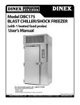
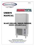
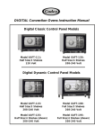
Model DBC30
BLAST CHILLER/SHOCK FREEZER
User’s Manual
For Service Information, call 1-888-673-4639
Please provide following information:
• Model number
• Serial number
• Part Description and number as shown in parts list.
Printed in the USA
Manual No. DBC30 Rev-03/08
DINEX INTERNATIONAL, INC. • 628-2 HEBRON AVENUE, GLASTONBURY CT 06033 • WWW.DINEX.COM
INDEX
Index. . . . . . . . . . . . . . . . . . . . . . . . . . . . . . . . . . . . . . . . . . . . . . . . . . . . . . . . . . . . . . . . . . . . . . . . . . . . . . . . . . . . . . . . . . . . . . . . . . . . . . . . . . . . . . . . . 2
Introduction . . . . . . . . . . . . . . . . . . . . . . . . . . . . . . . . . . . . . . . . . . . . . . . . . . . . . . . . . . . . . . . . . . . . . . . . . . . . . . . . . . . . . . . . . . . . . . . . . . . . . . . . . 3
Controller Features . . . . . . . . . . . . . . . . . . . . . . . . . . . . . . . . . . . . . . . . . . . . . . . . . . . . . . . . . . . . . . . . . . . . . . . . . . . . . . . . . . . . . . . . . . . . . . . . . . 3
Operating Modes. . . . . . . . . . . . . . . . . . . . . . . . . . . . . . . . . . . . . . . . . . . . . . . . . . . . . . . . . . . . . . . . . . . . . . . . . . . . . . . . . . . . . . . . . . . . . . . . . . . . 3
Automatic Mode. . . . . . . . . . . . . . . . . . . . . . . . . . . . . . . . . . . . . . . . . . . . . . . . . . . . . . . . . . . . . . . . . . . . . . . . . . . . . . . . . . . . . . . . . . . . . . . . . . . 3
Manual Mode. . . . . . . . . . . . . . . . . . . . . . . . . . . . . . . . . . . . . . . . . . . . . . . . . . . . . . . . . . . . . . . . . . . . . . . . . . . . . . . . . . . . . . . . . . . . . . . . . . . . . . 3
Operating Cycles . . . . . . . . . . . . . . . . . . . . . . . . . . . . . . . . . . . . . . . . . . . . . . . . . . . . . . . . . . . . . . . . . . . . . . . . . . . . . . . . . . . . . . . . . . . . . . . . . . . . 3
Additional Cycles . . . . . . . . . . . . . . . . . . . . . . . . . . . . . . . . . . . . . . . . . . . . . . . . . . . . . . . . . . . . . . . . . . . . . . . . . . . . . . . . . . . . . . . . . . . . . . . . . . . . 3
Installation. . . . . . . . . . . . . . . . . . . . . . . . . . . . . . . . . . . . . . . . . . . . . . . . . . . . . . . . . . . . . . . . . . . . . . . . . . . . . . . . . . . . . . . . . . . . . . . . . . . . . . . . . . . 3
Warnings. . . . . . . . . . . . . . . . . . . . . . . . . . . . . . . . . . . . . . . . . . . . . . . . . . . . . . . . . . . . . . . . . . . . . . . . . . . . . . . . . . . . . . . . . . . . . . . . . . . . . . . . . . . . 3
Preparation . . . . . . . . . . . . . . . . . . . . . . . . . . . . . . . . . . . . . . . . . . . . . . . . . . . . . . . . . . . . . . . . . . . . . . . . . . . . . . . . . . . . . . . . . . . . . . . . . . . . . . . . . 3
Installation . . . . . . . . . . . . . . . . . . . . . . . . . . . . . . . . . . . . . . . . . . . . . . . . . . . . . . . . . . . . . . . . . . . . . . . . . . . . . . . . . . . . . . . . . . . . . . . . . . . . . . . . . . 3
Dimensions. . . . . . . . . . . . . . . . . . . . . . . . . . . . . . . . . . . . . . . . . . . . . . . . . . . . . . . . . . . . . . . . . . . . . . . . . . . . . . . . . . . . . . . . . . . . . . . . . . . . . . . . 3
Location. . . . . . . . . . . . . . . . . . . . . . . . . . . . . . . . . . . . . . . . . . . . . . . . . . . . . . . . . . . . . . . . . . . . . . . . . . . . . . . . . . . . . . . . . . . . . . . . . . . . . . . . . . . 3
Using the DBC30 Technology . . . . . . . . . . . . . . . . . . . . . . . . . . . . . . . . . . . . . . . . . . . . . . . . . . . . . . . . . . . . . . . . . . . . . . . . . . . . . . . . . . . . . . . . 4
Blast Chilling . . . . . . . . . . . . . . . . . . . . . . . . . . . . . . . . . . . . . . . . . . . . . . . . . . . . . . . . . . . . . . . . . . . . . . . . . . . . . . . . . . . . . . . . . . . . . . . . . . . . . . . . 4
Shock Freezing . . . . . . . . . . . . . . . . . . . . . . . . . . . . . . . . . . . . . . . . . . . . . . . . . . . . . . . . . . . . . . . . . . . . . . . . . . . . . . . . . . . . . . . . . . . . . . . . . . . . . . 4
Soft Chill Cycle . . . . . . . . . . . . . . . . . . . . . . . . . . . . . . . . . . . . . . . . . . . . . . . . . . . . . . . . . . . . . . . . . . . . . . . . . . . . . . . . . . . . . . . . . . . . . . . . . . . . . . 4
Hard Chill Cycle . . . . . . . . . . . . . . . . . . . . . . . . . . . . . . . . . . . . . . . . . . . . . . . . . . . . . . . . . . . . . . . . . . . . . . . . . . . . . . . . . . . . . . . . . . . . . . . . . . . . . 4
Shock Freeze Cycle . . . . . . . . . . . . . . . . . . . . . . . . . . . . . . . . . . . . . . . . . . . . . . . . . . . . . . . . . . . . . . . . . . . . . . . . . . . . . . . . . . . . . . . . . . . . . . . . . . 4
Control Panel for Blast Chiller for Model DBC30 Blast Chiller. . . . . . . . . . . . . . . . . . . . . . . . . . . . . . . . . . . . . . . . . . . . . . . . . . . . . . . . 5
Keyboard Keys . . . . . . . . . . . . . . . . . . . . . . . . . . . . . . . . . . . . . . . . . . . . . . . . . . . . . . . . . . . . . . . . . . . . . . . . . . . . . . . . . . . . . . . . . . . . . . . . . . . . . . 5
Key Combinations . . . . . . . . . . . . . . . . . . . . . . . . . . . . . . . . . . . . . . . . . . . . . . . . . . . . . . . . . . . . . . . . . . . . . . . . . . . . . . . . . . . . . . . . . . . . . . . . . . . 5
Programming . . . . . . . . . . . . . . . . . . . . . . . . . . . . . . . . . . . . . . . . . . . . . . . . . . . . . . . . . . . . . . . . . . . . . . . . . . . . . . . . . . . . . . . . . . . . . . . . . . . . . . . . 6
1. Initial Programming . . . . . . . . . . . . . . . . . . . . . . . . . . . . . . . . . . . . . . . . . . . . . . . . . . . . . . . . . . . . . . . . . . . . . . . . . . . . . . . . . . . . . . . . . . . . . . . 6
2. Programming the Cycles . . . . . . . . . . . . . . . . . . . . . . . . . . . . . . . . . . . . . . . . . . . . . . . . . . . . . . . . . . . . . . . . . . . . . . . . . . . . . . . . . . . . . . . . . . 7
Automatic Cycle Parameters Programming (Blast Chiller Mode). . . . . . . . . . . . . . . . . . . . . . . . . . . . . . . . . . . . . . . . . . . . . . . . . . . . . 8
Manual Cycle Parameters Programming (Blast Chiller Mode). . . . . . . . . . . . . . . . . . . . . . . . . . . . . . . . . . . . . . . . . . . . . . . . . . . . . . . . 8
3. Programming the Unit as a Shock Freezer . . . . . . . . . . . . . . . . . . . . . . . . . . . . . . . . . . . . . . . . . . . . . . . . . . . . . . . . . . . . . . . . . . . . . . . . . . 9
Automatic Cycle Parameters Programming (Shock Freezer Mode) . . . . . . . . . . . . . . . . . . . . . . . . . . . . . . . . . . . . . . . . . . . . . . . . . . 9
Manual Cycle Parameters Programming (Shock Freezer Mode) . . . . . . . . . . . . . . . . . . . . . . . . . . . . . . . . . . . . . . . . . . . . . . . . . . . . 10
Operation. . . . . . . . . . . . . . . . . . . . . . . . . . . . . . . . . . . . . . . . . . . . . . . . . . . . . . . . . . . . . . . . . . . . . . . . . . . . . . . . . . . . . . . . . . . . . . . . . . . . . . . . . . . 11
1. Automatic Cycle . . . . . . . . . . . . . . . . . . . . . . . . . . . . . . . . . . . . . . . . . . . . . . . . . . . . . . . . . . . . . . . . . . . . . . . . . . . . . . . . . . . . . . . . . . . . . . . . . . . 11
2. Manual Cycle . . . . . . . . . . . . . . . . . . . . . . . . . . . . . . . . . . . . . . . . . . . . . . . . . . . . . . . . . . . . . . . . . . . . . . . . . . . . . . . . . . . . . . . . . . . . . . . . . . . . . . 12
3. Defrost Cycle . . . . . . . . . . . . . . . . . . . . . . . . . . . . . . . . . . . . . . . . . . . . . . . . . . . . . . . . . . . . . . . . . . . . . . . . . . . . . . . . . . . . . . . . . . . . . . . . . . . . . . 13
Maintenance and Cleaning . . . . . . . . . . . . . . . . . . . . . . . . . . . . . . . . . . . . . . . . . . . . . . . . . . . . . . . . . . . . . . . . . . . . . . . . . . . . . . . . . . . . . . . . . 14
Cleaning the Condenser. . . . . . . . . . . . . . . . . . . . . . . . . . . . . . . . . . . . . . . . . . . . . . . . . . . . . . . . . . . . . . . . . . . . . . . . . . . . . . . . . . . . . . . . . . . . 14
Cleaning the Storage Compartment . . . . . . . . . . . . . . . . . . . . . . . . . . . . . . . . . . . . . . . . . . . . . . . . . . . . . . . . . . . . . . . . . . . . . . . . . . . . . . . . 14
Wiring Diagrams. . . . . . . . . . . . . . . . . . . . . . . . . . . . . . . . . . . . . . . . . . . . . . . . . . . . . . . . . . . . . . . . . . . . . . . . . . . . . . . . . . . . . . . . . . . . . . . . . . . . 15
Parts List. . . . . . . . . . . . . . . . . . . . . . . . . . . . . . . . . . . . . . . . . . . . . . . . . . . . . . . . . . . . . . . . . . . . . . . . . . . . . . . . . . . . . . . . . . . . . . . . . . . . . . . . . . . . 18
Dinex® Warranty. . . . . . . . . . . . . . . . . . . . . . . . . . . . . . . . . . . . . . . . . . . . . . . . . . . . . . . . . . . . . . . . . . . . . . . . . . . . . . . . . . . . . . . . . . . . . . . . . . . . 19
Page 2
INTRODUCTION
OPERATING CYCLES
The operator can choose from the following 2 operating
cycles:
You have just purchased the new Dinex Equipment. Please
read this manual for helpful guidelines on how to use your
Equipment. Should you have any questions concerning
the Equipment, please call the Dinex Hotline at 1-888-6734639 (Monday through Friday from 8 am to 5 pm, Eastern
Standard Time).
END FOOD
TEMPERATURE
MODE
38° F To 40° F Air temp. starts at 0°F, rises to 28°F
to 35° F when food core temp.
reaches 60°F
Automatic
The Model DBC30 Blast Chiller/Shock Freezer is used to rapidly chill cooked foods to temperatures suitable for refrigerated or frozen storage. It has a capacity of (3) 12" x 20" x 21/2" pans (not included). Model DBC30, in Chiller mode, is
capable of lowering the core temperature of up to 30 lbs. of
food from 160° F to 40° F within 90 minutes. In Shock Freeze
mode it is capable of lowering the core temperature of up
to 18 lbs. of food from 160° F to 0° F within 4 hours. Model
DBC30 employs a high velocity flow of cooled air to assure
even cooling of the entire load of food, and to quickly bring
the food temperature through the danger zone in which
bacteria multiply rapidly. This is done in accordance with
HACCP, FDA and all state regulations.
NOTES
38° F To 40° F
Manual
For 1 hour air temperature is
maintained between 0°F and10°F
and for another hour is maintained between 28°F and 35°F
All Chill Cycles automatically go into HOLDING
! NOTE:
MODE when the selected food core temperature is reached
and remain there until the operator stops the cycle.
ADDITIONAL CYCLES
CONTROLLER FEATURES
The electronic control system is solid state and is based on
the latest microprocessor technology. The display is VFD
Industrial Type. It displays 2 lines of 20 characters each and
allows operator viewing from any angle. The display is programmed to show clear step-by-step instructions and
operating data. The unit has built-in safety and self-diagnostic systems. The controller notifies the operator if various faults, as listed below, should occur:
MODE
Defrost
USES
To defrost the
evaporator, not the food.
NOTES
Use when necessary.
INSTALLATION
• Faulty air temperature probe
• Faulty food temperature probe
• High air temperature (above 140° F)
• Low air temperature (below -35° F)
• High food temperature (above 180° F)
• Low food temperature (below 35° F)
• Excessively high pressure.
Read and carefully follow all of the instructions in
! WARNING:
this manual before you attempt to install this equipment.
Any changes made to the equipment without
! NOTE:
authorization from the factory will void the warranty.
OPERATING MODES
PREPARATION
The operator can choose from the following modes:
Automatic Mode
• Check the integrity of the unit once it is unpacked
• Check to make sure the floor is level
• Check that the available power supply (Voltage, # of
phases, Hz, Amps, max. fuse size) corresponds to the
ratings on the nameplate and that correctly rated
electrical protection is provided (VOLTAGE MUST BE
WITHIN ± 5% FROM THE NAMEPLATE VALUE).
This is the preferred mode, in which the food probe is
active and takes part in controlling the chilling or freezing
processes. The cycle will never proceed to its next step
until the food probe has reached its set breaking temperature. The operator needs only to insert the probe into the
food. It is recommended that the operator remove the
food when its temperature starts to flash and the display
shows “Ready”. The unit will automatically switch into
holding mode (cavity air temperature between 35° F
and 42° F) when the food has reached the end cycle
programmed temperature.
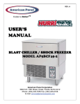
INSTALLATION
Dimensions
Overall dimensions are 25 1/4" left to right, 25 7/8" front to
back, 34" height. With the door open 90° the front to back,
distance is 48 3/4".
Manual Mode
Operating time is set manually, by the operator, for the
meal that has been chosen. Air temperature is controlled
by the air probe. If the food probe has been inserted into
the food it will provide temperature readouts only. The
unit will automatically switch into the holding mode at the
end of the cycle.
Location
Ambient air temperature should be no greater than 90°F
to ensure the rated performance.
Do NOT install the unit near a heat source, in an area
Page 3
USING THE DBC30
TECHNOLOGY
exposed to direct sunlight, or in a closed area with high
temperatures and insufficient air change.
Level the unit by rotating its adjustable feet, ensuring that
the weight of the unit is off the legs when doing so.
BLAST CHILLING
Make certain that the unit is correctly leveled - correct
functioning may be compromised if it is not.
All cooked food rapidly loses its quality and aroma if it is
not served promptly. Natural bacteria growth, the main
reason why food becomes stale, takes place at an exponential rate between 140°F and 40°F. However lower temperatures have a hibernating effect that increases as the
temperature drops, thereby gradually reducing bacterial
activity until it stops altogether. Only fast reduction of the
temperature at the product's core allows its initial characteristics to be maintained intact. The DBC30 blast chiller
gets food through this high-risk temperature band rapidly,
cooling the core of the product to 40°F within 90 minutes.
This conserves food quality, color and aroma while increasing its storage life. After blast chilling, the food can be preserved at 38°F for up to 5 days.
Mount the rails for the drain pan, using the screws sent
with the unit. The mounting inserts are already in place
under the unit. Slide the drain pan on the rails.
Plug the power supply cord into a proper outlet in accordance with the chart below.
MODEL
VOLTAGE
HZ
HP
AMPS
NOTES
DBC30
120, 1 PH
60
1
10
5-15P
SHOCK FREEZING
Spaces Around The Cabinet
For storage over the medium-long term, food has to be
shock frozen (to 0°F or below). Freezing means converting
the water contained in food into crystals. Thanks to the
high speed at which low temperature penetrates the food,
the DBC30 shock freezer assures the formation of small
crystals (micro-crystals) that do not damage the product in
any way. Uncooked raw materials, semi-processed food
and cooked food can be treated safely. When the food is
thawed, no liquids, consistency, weight or aroma will be
lost, and all its initial qualities will remain unchanged.
• At least 1" clear space is required on the right side of the
cabinet for air flow and service.
• At least 2.5" clear space is required on the left side of the
cabinet for door opening and air flow.
• At least 3" clear space is required on the rear of the
cabinet for optimum air flow.
• Enough space should be provided in front of the cabinet
to fully open the door.
SOFT CHILL CYCLE
(160°F to 40°F)
This cycle is recommended for "delicate", light, thin products or small piece sizes, such as vegetables, creams,
sweets, fish products and fried foods. Soft chilling lowers
the food temperature quickly, but extremely delicately so
as not to damage the outside of the food. This is the ideal
cycle to chill any food quickly but delicately, even in haute
cuisine.
HARD CHILL CYCLE
(160°F TO 40°F)
Hard chilling is suited for "dense" products and products
with a high fat content, in large pieces or those products
typically more difficult to chill. Careful chilling control
ensures that the end temperature of 40°F is reached at the
core of the product, with no danger of freezing and
damaging the product, not even on its surface.
Optional Stand
SHOCK FREEZE CYCLE
(160°F TO 0°F)
This cycle is recommended when you want to store food
for several weeks or months, at temperatures below 0°F.
Freezers are suited for storing ready frozen foods, but not
for freezing them. During shock freezing, the liquids contained in the food are transformed into micro-crystals that
do not harm the tissue structure. When the food is used
and thawed, its quality will be excellent. It is especially
suited for all semi-processed food and raw products.
Page 4
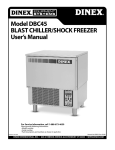
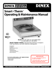
FOR MODEL DBC30 BLAST CHILLER
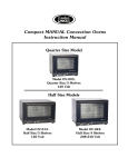
KEYBOARD KEYS
ON/OFF
START/STOP
A – automatic cycle
M – manual cycle
UP, DOWN, SELECT, ENTER – programming keys
KEY COMBINATIONS
• Initial Programming state – to initially set the device
Press and hold “START/STOP” for 5 seconds
• Cycles programming state – to initially set A and M cycles
Press “ENTER” for 1 second
• Load default values
Press “DOWN” for 10 seconds
• Ready To Go state in order to start a cycle
Press “ON/OFF”
• Defrost
Press UP for 5 sec.
Page 5
PROGRAMMING
1. INITIAL PROGRAMMING
! desired. If no changes are to be made, skip to Page 7.
NOTE: Initial programming is preset at the factory (the unit is configured as a blast chiller). Use this section only if changes are
(2. Programming the cycles).
OFF
a. With the display reading "OFF", press
("START/STOP") for 5 seconds.
b. When entering initial programming state, the display
will show for 3 seconds:
INITIAL PROGRAMMING
ENTER PASSWORD
After 3 seconds – or if a key is pressed – the display will show:
c. Enter the default password by pressing, in order, the
and
ENTER PASSWORD
***
keys.
d. If you do not wish to change the password, press
CHANGE PASSWORD?
NO
.
To change the default password, press
for "YES" then press
or
.
The password will always be a combination of three of the four following keys:
("AUTO", "MANUAL","UP","DOWN",).
Type the new password, then press
Be sure to remember the new password and keep a record of it in a safe place.
The high air alarm temperature should be left at
140 °F. However, if a change is desired:
e. To change the temperature, press
then press
HIGH AIR ALARM
140°F
Blinks
or
.
The low air alarm temperature should be left at
-35°F. However, if a change is desired:
f. To change the temperature, press
then press
140
LOW AIR ALARM
-35°F
or
.
Page 6
-35
Blinks
The high food alarm temperature should be left
at 180 °F. However, to make a change:
g. To change the temperature, press
then press
180
Blinks
LOW FOOD ALARM
35°F
35
Blinks
or
.
The low food alarm temperature should be left at
35°F (blast chiller configuration).
However, to make a change:
h. To change the temperature, press
then press
HIGH FOOD ALARM
180°F
or
.
The unit is preprogrammed in the factory as a blast chiller.
To program the unit as a shock freezer, the low food alarm temperature should be set at -5 °F.
i. To change the defrost time, press
then press
DEFROST TIME
05 MIN
or
.
INITIAL PROGRAMMING
COMPLETE
The display will show for 2 seconds:
OFF
After 3 seconds – or if a key is pressed – the display
will enter “OFF” state:
time during programming
key can be used to return to the previous screen.
! NOTE: Atkeyanyis used
to confirm the settings and advance to the next screen.
2. PROGRAMMING THE CYCLES
OFF
a. With the display reading "OFF", press and hold
for 1 second.
ENTER PASSWORD
***
b. Enter your password (see page 6), then press
When entering cycles programming state, the display will show.
Page 7
PROGRAMMING MODE
CHOOSE CYCLE
05
Blinks
AUTOMATIC CYCLE PARAMETERS PROGRAMMING (BLAST CHILLER MODE)
c. Press
PROGRAMMING MODE
CHOOSE CYCLE
to program the automatic mode.
The display will show for 3 seconds:
After 3 seconds – or if ENTER is pressed – the display will show:
d. To change the temperature, press
then press
or
LOW AIR PART 1
0°F
0
Blinks
or
HIGH AIR PART 1
10°F
10
Blinks
.
e. To change the temperature, press
then press
PROGRAMMING MODE
AUTOMATIC CYCLE
.
f. To change the temperature, press
then press
BREAKING TEMPERATURE 60
60°F
Blinks
or
.
g. To change the temperature, press
then press
LOW AIR PART 2
28°F
or
.
h. To change the temperature, press
then press
or
HIGH AIR PART 2
35°F
or
FINAL FOOD TEMP
40°F
or
HOLDING LOW TEMP
35°F
35
Blinks
.
i. To change the temperature, press
then press
40
Blinks
.
j. To change the temperature, press
then press
35
Blinks
.
k. To change the temperature, press
then press
HOLDING HIGH TEMP
42°F
or
.
The display will show:
PROGRAMMING MODE
CHOOSE CYCLE
MANUAL CYCLE PARAMETERS PROGRAMMING
(BLAST CHILLER MODE)
PROGRAMMING MODE
CHOOSE CYCLE
l. Press
28
Blinks
to program the manual mode.
PROGRAMMING MODE
MANUAL CYCLE
The display will show for 3 seconds:
Page 8
42
Blinks
After 3 seconds – or if ENTER is pressed – the display
will show:
m. To change the temperature, press
then press
or
HIGH AIR PART 1
10°F
or
10
Blinks
.
o. To change the time, press
then press
TIME 1
H 01:00 MIN
01:00
Blinks
or
LOW AIR PART 2
28°F
28
Blinks
or
HIGH AIR PART 2
35°F
35
Blinks
or
.
p. To change the temperature, press
then press
.
q. To change the temperature, press
then press
.
r. To change the time, press
then press
TIME 2
H 01:00 MIN
or
01:00
Blinks
.
s. To change the temperature, press
HOLDING LOW TEMP
35°F
or
t. To change the temperature, press
then press
0
Blinks
.
n. To change the temperature, press
then press
LOW AIR PART 1
0°F
HOLDING HIGH TEMP.
42°F
or
35
Blinks
42
Blinks
.
The display will show: then press
PROGRAMMING MODE
CHOOSE CYCLE
.
3. PROGRAMMING THE UNIT AS A SHOCK FREEZER
The unit is programmed at the factory as a blast chiller. However it can be reprogrammed as a shock freezer.
To accomplish this, go to INITIAL PROGRAMMING on page 6, see step h and set the low food alarm temperature at -5 oF (all other
parameters in the INITIAL PROGRAMMING will stay the same in shock freezer mode as in blast chiller mode). Then start CYCLE PROGRAMMING (steps a and b) as shown on page 7. The rest of CYCLE PROGRAMMING should be done as follows:
AUTOMATIC CYCLE PARAMETERS PROGRAMMING (SHOCK FREEZER MODE)
c. Press
PROGRAMMING MODE
CHOOSE CYCLE
to program the automatic mode.
Page 9
The display will show for 3 seconds:
After 3 seconds – or if ENTER is pressed – the display will show:
d. Set the temperature at -25°F by pressing
then press
or
LOW AIR PART 1
-25°F
.
e. Set the temperature at -15°F by pressing
then press
PROGRAMMING MODE
AUTOMATIC CYCLE
HIGH AIR PART 1
-15°F
or
-25
Blinks
-15
Blinks
.
f. Set the temperature at 40°F by pressing
BREAKING TEMPERATURE 40
40°F
or
Blinks
then press
.
g. Set the temperature at -25°F by pressing
then press
or
LOW AIR PART 2
-25°F
-25
Blinks
or
HIGH AIR PART 2
-15°F
-15
.
h. Set the temperature at -15°F by pressing
then press
Blinks
.
i. Set the temperature at 0°F by pressing
then press
FINAL FOOD TEMP
0°F
or
0
Blinks
.
j. Set the temperature at -4°F by pressing
then press
HOLDING LOW TEMP
-4°F
or
-4
Blinks
.
k .Set the temperature at 3°F by pressing
then press
HOLDING HIGH TEMP
3°F
or
3
Blinks
.
PROGRAMMING MODE
CHOOSE CYCLE
The display will show:
MANUAL CYCLE PARAMETERS PROGRAMMING (SHOCK FREEZER MODE)
l. Press
PROGRAMMING MODE
CHOOSE CYCLE
to program the manual mode.
The display will show for 3 seconds:
After 3 seconds – or if ENTER is pressed – the display will show:
m.Set the temperature at -25°F by pressing
then press
PROGRAMMING MODE
AUTOMATIC CYCLE
LOW AIR PART 1
-25°F
or
.
Page 10
-25
Blinks
n. Set the temperature at -15°F by pressing
then press
HIGH AIR PART 1
-15°F
-15
Blinks
TIME 1
H 02:00 MIN
02:00
Blinks
or
LOW AIR PART 2
-25°F
-25
Blinks
or
HIGH AIR PART 2
-15°F
-15
or
.
o. Set the time at 2 hours by pressing
then press
or
.
Press and hold
or
to increase or decrease the time in 30 minutes steps.
p. Set the temperature at -25°F by pressing
then press
.
q. Set the temperature at -15°F by pressing
then press
Blinks
.
r. Set the time at 2 hours by pressing
then press
or
TIME 2
H 02:00 MIN
02:00
Blinks
HOLDING LOW TEMP
-4°F
-4
Blinks
.
s. Set the temperature at -4°F by pressing
then press
or
.
t. Set the temperature at 3°F by pressing
then press
HOLDING HIGH TEMP
3°F
or
3
Blinks
.
PROGRAMMING MODE
CHOOSE CYCLE
The display will show:
OPERATION
1. AUTOMATIC CYCLE
a. With the display reading "OFF", press the
b. To start the cycle, press
or
Pressing
(“ON/OFF”) key.
("START/STOP") key,
key to select MANUAL cycle. Then the display will show::
key will switch back to AUTOMATIC mode.
If no key is pressed for 5 minutes, the unit will switch to OFF state.
Page 11
OFF
CHOOSE CYCLE
AUTOMATIC
AUTOMATIC
CHOOSE CYCLE
MANUAL
MANUAL
Blinks
Blinks
c. If after b. the
("START/STOP") key was pressed,
the AUTOMATIC cycle will start.
AIR
FOOD
The display will show:
alternating each 5 seconds with
75°F
140°F
AUTOMATIC CYCLE
ELAPSED TIME 00:00
00:00
Will count up
The AUTOMATIC mode uses both the food probe and air probe temperatures to control the cycle. When the food temperature
has reached the final setting of 40° F (in blast chiller mode, 0° F in shock freezer mode), the unit will automatically go into
holding mode and a beep will sound for 5 seconds. The elapsed time and food temperature read-outs will blink.
The display will now show:
HOLDING CYCLE A
ELAPSED TIME 01:29
alternating with
alternating with
The operator can now end this cycle by pressing the
34°F
40°F
AIR
FOOD
34°F
Ready
CYCLE A
Blinks
("START/ STOP") key.
CHOOSE CYCLE
AUTOMATIC
The display will now show:
Press the
AIR
FOOD
HOLDING
(“ON/OFF”) key to enter OFF state.
2. MANUAL CYCLE
a. With the display reading "OFF", press the
(“ON/OFF”) key.
Then the display will show:
b. Press
OFF
CHOOSE CYCLE
AUTOMATIC
key to select MANUAL cycle.
CHOOSE CYCLE
MANUAL
Then the display will show:
AUTOMATIC
Blinks
MANUAL
Blinks
Cycle time can be changed only in Programming mode. To change the programmed cycle time for any cycle see the instructionS
pages 7 to 11.
c. Press the
("START/STOP") key to start the cycle.
AIR
FOOD
The display will show:
alternating with
75°F
140°F
MANUAL CYCLE
REMAINING TIME 01:59
01:59
Will count
down
The MANUAL mode uses time and the air probe temperature to control the cycle. The default total time for a hard cycle is 120
minutes. After the 120 minutes the unit will automatically go into holding mode.
HOLDING CYCLE M
REMAINING TIME 00:00
AIR
34°F
FOOD
40°F
The display will now show:
alternating with
Page 12
HOLDING
CYCLE M
Blinks
40°F Blinks
The operator can now end this cycle by pressing
("START/ STOP").
CHOOSE CYCLE
MANUAL
The display will show now:
Press the
(“ON/OFF”) key to enter OFF state.
3. DEFROST CYCLE
The defrost cycle runs the evaporator fan for 5 minutes with the door open.
a. To perform a defrost cycle, from OFF state press and hold
for 5 seconds.
If the door is not opened the display will show:
DEFROST CYCLE
OPEN THE DOOR!
b. Open the door.
DEFROST CYCLE
PRESS START
If the door is open the display will show:
c. Press the
OFF
("UP") key
("START/STOP") key to start the defrost cycle.
The display will now show:
DEFROST CYCLE
REMAINING TIME 04:59
After 5 minutes the display will show:
The controller will beep for a few seconds.
DEFROST CYCLE
REMAINING TIME 00:00
!
NOTE: To stop any cycle before it has finished,
press
("START/STOP").
The controller will beep for a few seconds. If you still want to stop the cycle,
press
("START/STOP") again. If you do NOT want to stop, do nothing
UNIT IN PROCESS!
DO YOU WANT TO STOP?
and the cycle will continue.
At any time during programming or operation, if
(“ON/OFF”) key is pressed the unit will enter OFF state.
Page 13
04::59
Will count
down to 00:00
00::00
Blinks
CLEANING THE STORAGE COMPARTMENT
MAINTENANCE AND CLEANING
Clean the inside of the storage compartment daily to avoid
altering the taste and aroma of the food. Clean the inside,
the grid supports and the grids with a mild detergent and
then rinse thoroughly. The storage compartment and its
internal components have been designed to aid all cleaning operations. Clean the outside surfaces regularly with a
detergent for stainless steel and dry using a soft cloth.
Always defrost the unit (see manual).
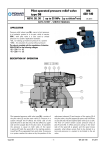
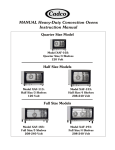
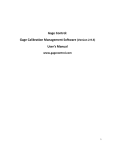
CLEANING THE CONDENSER
For correct and efficient operation of the blast chiller, it is
necessary that the condenser be kept clean so that air can
circulate around it freely and come into contact with the
whole of its surface.
DO NOT USE ABRASIVES, SOLVENTS OR GLASS WOOL
(Fig. 3).
Avoid using sharp implements and abrasives, especially
when cleaning the evaporator (Fig. 2).
Figure 1
This operation (to be performed every 30 days, max.) can
be accomplished using a brush (non-metallic) to remove all
the dust and dirt from the condenser fins. Remove the
finned grid to gain access to the condenser.
Figure 2
Figure 3
If additional refrigerant should be needed, be
! NOTE:
certain to use the correct type and amount as shown
on the nameplate.
Page 14
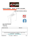
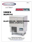
Page15
Electrical Wiring Schematic
Page 16
Electrical Wiring Schematic
Page 17
Electrical Wiring Schematic
PARTS LIST
Part Number
Description
AC 990100
Electronic Board AP3 (A)
AC 990108
Air Probe PT 100
AC 990176
Compressor Aspera (R404A Refrigerant)
AC 990124
Cond. Fan Motor
AC 990133
Evaporator Fan
AC 990137
Food Probe (Not Heated)
AC 990147
Magnetic Door Switch
AC 990150
Relay 10 A Finder
AC 990153
Solenoid
AC 990158
Transformer
AC 991018
Condenser
AC 991022
Evaporator
AC 991026
Expansion Valve
AC 991028
Filter Drier
AC 991030
High Pressure Switch
AC 991032
Liquid Receiver
AC 991036
Orifice 00
AC 991038
Sight Glass
AC 991041
Solenoid Valve EVR3
AC 993020
Door Gasket 23-3/4” x 14-1/2”
AC 993028
Drip Pan
AC 990191
Relay 30A Finder
AC 992087
Wire Shelf
Page 18
exclusive remedy shall be the re-performance of the services by Dinex.
The foregoing remedies are Customer’s exclusive remedies and Dinex’s
sole liability for warranty claims under this warranty statement.This
exclusive remedy shall not have failed of its essential purpose (as that
term is used in the Uniform Commercial Code) as long as Dinex
remains willing to repair or replace defective Warranted Products within a commercially reasonable time after being notified of Customer’s
warranty claim.
DINEX® Warranty
These Warranties cover the following Dinex International, Inc.(“Dinex”)
equipment products (the “Warranted Products”):
• Rethermalization Equipment Products
• Induction Heating System Products (excluding Induction Bases
covered under separate warranty)
• Milk Cooler Products
• Ice Cream Freezer Products
• Air Curtain Refrigerator Products
• Blast Chiller Products
• Hot/Cold Food Counter Products
• Plate, Rack and Tray Dispenser Products
• Plate Heater Products
• Base Heater Products
• Drying and Storage Rack Products
• Starter Station Products
• Conveyer Products
• Tray and Other Cart Products
LIMITATIONS
THESE WARRANTIES ARE EXCLUSIVE AND IN LIEU OF ALL OTHER WARRANTIES,WHETHER WRITTEN, ORAL, EXPRESSED, IMPLIED OR STATUTORY.EXCEPT AS PROVIDED HEREIN, NO EXPRESS OR IMPLIED WARRANTIES, INCLUDING BUT NOT LIMITED TO IMPLIED WARRANTIES OF
MERCHANTABILITY, FITNESS FOR A PARTICULAR PURPOSE, QUIET
ENJOYMENT, SYSTEM INTEGRATION AND DATA ACCURACY,WILL
APPLY.THERE ARE NO WARRANTIES THAT EXTEND BEYOND THOSE
DESCRIBED IN THIS DOCUMENT AND NO PRIOR STATEMENTS BY ANY
OF DINEX’S REPRESENTATIVES SHALL MODIFY OR EXPAND THESE
WARRANTIES.DINEX AND DINEX’S AFFILIATES AND REPRESENTATIVES
SHALL HAVE NO LIABILITY TO CUSTOMER FOR (1) ANY SPECIAL, PUNITIVE, INCIDENTAL, INDIRECT OR CONSEQUENTIAL DAMAGES ARISING
OUT OF OR IN CONNECTION WITH THE WARRANTED PRODUCTS,
REGARDLESS OF WHETHER SUCH LIABILITY SHALL BE CLAIMED IN
CONTRACT,TORT, EQUITY OR OTHERWISE, (2) ANY ASSISTANCE NOT
REQUIRED UNDER DINEX’S QUOTATION OR (3) ANYTHING OCCURRING
AFTER THE WARRANTY PERIOD ENDS.
Warranted Products also includes any other Equipment System Products
identified on Dinex’s website (www.dinex.com) from time to time.
Standard Warranty. Except as indicated otherwise below, Dinex warrants that the Warranted Products will be free from defects in title,
material and workmanship under normal use and service and will perform substantially in accordance with Dinex’s written technical specifications for the Warranted Products (as such specifications exist on the
date the Warranted Products are shipped) (the “Product Specifications”).
This warranty covers both parts and labor and is available only to endusers (the “Customers”) that purchase the Warranted Products from
Dinex or its authorized distributors.For the purpose of these warranties,
a defect is determined by Dinex after its good faith investigation.
DINEX’S STANDARD WARRANTIES ONLY APPLY TO END-USER-PURCHASERS LOCATED IN THE UNITED STATES AND CANADA.ANY SALE TO
END-USER-PURCHASERS OUTSIDE THE UNITED STATES AND CANADA
WILL BE SUBJECT TO COMMERCIAL TERMS SPECIFICALLY AGREED BY
DINEX AND THE END-USER PURCHASER.DINEX MAKES NO WARRANTY,
EXPRESS OR IMPLIED,TO END-USER-PURCHASERS OUTSIDE THE UNITED
STATES OR CANADA UNLESS OTHERWISE EXPRESSLY AGREED IN WRITING.
Dinex Software. In addition to the other warranties set forth herein,
with respect to Dinex’s licensed software, Dinex warrants that it has the
right to license or sublicense the software to Customer for the purposes
and subject to the terms and conditions set forth in Dinex’s standard
terms and conditions.
These warranties do not apply to, and Dinex shall not have any obligation to Customer hereunder with respect to, any warranty claim resulting from or arising out of: (i) normal wear and tear; (ii) damage caused
by shipping or accident; (iii) damage caused by improper installation,
repair or alteration not performed by Dinex; (iv) the use of the
Warranted Product in combination with any software, tools, hardware,
equipment, supplies, accessories or any other materials or services, not
furnished by Dinex or recommended in writing by Dinex; (v) the use of
the Warranted Product in a manner or environment, or for any purpose, for which Dinex did not design or license it, or inconsistent with
Dinex’s recommendations or instructions on use including, but not limited to, power supply requirements identified in Product Specifications;
(vi) any alteration, modification or enhancement of the Warranted
Product by Customer or any third party not authorized or approved in
writing by Dinex; (vii) Warranted Product manufactured to meet customer specifications or designs; or (viii) any accessories or supplies or
other equipment or products that may be delivered with the
Warranted Product.
Supplies and Accessories. Dinex’s warranty for its supplies and accessories that are shipped with Warranted Products is covered by a separate warranty statement, which is available at www.dinex.com.
Services. Dinex warrants that any service it provides to Customer will
be performed by trained individuals in a workmanlike manner.
DURATION
Dinex provides a one year warranty for the Warranted Products.The warranty period begins on the date the Warranted Products are shipped to
Customer.The warranty period for any Warranted Product or part furnished to correct a warranty failure will be the unexpired term of the
warranty applicable to the repaired or replaced Warranted Product.
In addition, these warranties do not cover: (i) Any defect or deficiency
(including failure to conform to Product Specifications) that results, in
whole or in part, from any improper storage or handling, failure to
maintain the Warranted Products in the manner described in any
applicable instructions or specifications, inadequate back-up or virus
protection or any cause external to the Warranted Products or beyond
Dinex’s reasonable control, including, but not limited to, power failure
and failure to keep Customer’s site clean and free of dust, sand and
other particles or debris; (ii) the payment or reimbursement of any
facility costs arising from repair or replacement of the Warranted
Products; (iii) any adjustment, such as alignment, calibration, or other
normal preventative maintenance required of Customer; and (iv)
expendable supply items.
REMEDIES
If Customer promptly notifies Dinex of Customer’s warranty claim and
makes the Warranted Product available for service, Dinex will, at its
option, either repair or replace (with new or exchange replacement
parts) the non-conforming Warranted Product or parts of the
Warranted Product.With respect to Dinex’s licensed software, Dinex
will, at its option, either correct the non-conformity or replace the
applicable licensed software.Warranty service will be performed without charge from 8:00 a.m.to 5:00 p.m.EST, Monday-Friday, excluding
Dinex holidays, and outside those hours at Dinex’s then prevailing service rates and subject to the availability of personnel.With respect to
Dinex’s warranty for the services it provides to Customer, Customer’s
Page 19
WWW.DINEX.COM
DINEX INTERNATIONAL, INC.
628-2 HEBRON AVENUE, GLASTONBURY CT 06033 • 1.888.673.4639
Page 20