1
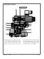
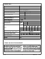
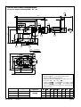
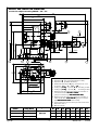
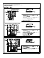
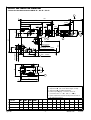
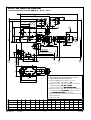
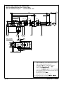
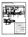
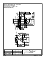
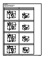
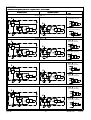
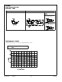
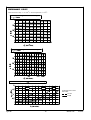
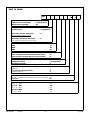
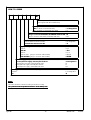
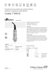
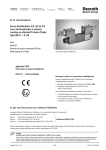
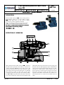
Pilot operated pressure relief valve
type DB
WK
420 140
NS10, 20, 30
up to 35 MPa up to 650 dm3/min
DATA SHEET - SERVICE MANUA
MANUAL
NUA L
07.2011
APPLICATION
Pressure relief valves type DB... serve to limit pressure
in a hydraulic system or in its part, while in version
DBW... with pilot valve it is also used to unload
pressure in a system. Application example:
•DB... for setting up maximum pressure in a system
•DBW... for actuation of a pump without pressure
The valve is complied with the regulations of directive
2006/95/WE for the following voltages:
voltages
•50
50 – 250 V for AC
•75
75 – 250 V for DC
DESCRIPTION OF OPERATION
DB20 - 2 - 52/100
10
2
6
3
5
Y
11
7
1
4
9
X
P
Pilot operated pressure relief valve type DB... consists of
the pilot valve (2) and the main valve (1). Pressure in a
system through line P affects the lower side of the
spool (4) and via jets (9), (10), (11) also affects its upper
side and the poppet (6) of the pilot valve. At standstill,
the pressure is equal on both sides of the spool.
A spring (7) holds the spool (4) in the starting position.
Lines P and T are separated from each other. If pressure
in a system reaches the value set by the position of the
Type DB
T
adjustment element (5) and tension of the spring (3) of
the pilot valve, the pilot poppet (6) opens and fluid flows
via jets (9) and (10) and opened pilot valve (2) to a tank.
The flow of control stream causes pressure drop at
jets (9) and (10). In effect pressure acting on the lower
side of the spool (4) is greater and the spool moves
upwards, what allows excess fluid to be drained to a
tank and pressure in a system to be limited to the set
value.
-1-
WK 420 140
07.2011
DESCRIPTION OF OPERATION
DBW20...A - 2 - 52/100
8
6
2
5
10
3
Y
11
7
1
4
9
X
P
T
Pressure relief valve is also available in version with
forced (electrically) pressure unloading. Pilot valve (8) in
form of a directional valve shuts off drain line before
the pilot poppet in its starting position. The valve
functions as described before. After switching
directional valve (9) the chamber before the pilot
WK 420 140
07.2011
poppet is connected to drain line (connected to a tank).
The unloaded spool (4) moves upwards opening
connection between P and T. The valve is available in
two versions depending on the pilot valve (8): closed in
de-energized position – version DBW…A
A… or opened
in de-energized position – version DBW…B
B… .
-2-
Type DB
TECHNICAL DATA
Hydraulic fluid
mineral oil
Req
Required fi
f iltrat
ltr ati
ation
up to
t o 1 6 µm
Recommended filtration
up to 10 µm
Nominal fluid viscosity
37 mm 2/s at temperature 55 C
Viscosity range
2,8 up to 380 mm 2/s
o
recommended 40 oC up to 55 C
max
-20 oC up to +70 oC
-20 oC up to +70 oC
version DB...
Fluid temperature range (in a tank)
Ambient temperature range
Maximum
imum operat
operati
ating press
pres sure
Maximum
imum press
pres sure in lines
nes Y , T
Minimum
imum setti
sett ing press
pres sure
Maximum
imum setting pres
pressure
Maximum
imum fl
f low rate
rate
Weight
Type of a d
direct
irectiional valve
irect
(only for versions DBW... ; DBW...G; DBWC...)
Nomi
ominal supply
upply voltage
ltage for
f or solen
lenoid
o
-20 oC up to +50 oC
version DBW...
3 5 MP a
versiion DB...
vers
31, 5 MPa
versi
ersion DBW...
2 1 MPa
0,5
0, 5 MPa
3 5 MP a
25
2 50 dm 3 / mi
m in
500 dm 3/ mi
m in
3
65
6 50 dm / mi
m in
version
NS1
NS10
NS2
NS20
NS3
NS
30
nomi
ominal
size
nominal
size
DB...
NS10
NS20
3,1 kg
4,0 kg
NS30
4,9 kg
DBG...
DBW...
4,9 kg 4,7 kg
4,7 kg 5,6 kg
5,4 kg 6,5 kg
DBWG... DBC... DBWC...
6,5 kg
6,3 kg
7,0 kg
1,5 kg
1,5 k g
1,5 kg
3,1 kg
3,1 kg
3,1 kg
WE6... according to data sheet WK 499 502
AC (plug-in connector with rectifier)
DC
12 V
24 V
Supply voltage tolerance
±10%
Power requirement (DC)
30 W
Insulati
ation
Temperature of solenoid coil
IP
I P 65
max 150 oC
11 0V
2 30 V - 5 0 Hz
11 0 V - 5 0H z
ASSEMBLY AND APPLICATION REQUIREMENTS
1. Only valve working properly and suitably installed may
be connected to an electric system. Only skilled workers
are allowed to connect and disconnect electric system.
2. Ground connection ( ) must be connected with
protective earth wire ( PE)
PE in supply system according to
appropriate instructions.
3. It is forbidden to apply the valve if the supply cable in
the gland of plugplug-in connector is not properly tightened.
Type DB
-3-
4. It is forbidden to apply the valve if the plugplug-in
connector is not properly tightened to the solenoid
socket and is not secured by screwing bolt tightly.
5. Due to heating solenoid coil,
coil, the valves should be
placed in order to eliminate the possibility of incidental
touch while using, or, they should be equipped with the
coil covers (in accordance with the European standards
PN - EN ISO 1373213732-1 and PN - EN 982).
WK 420 140
07.2011
OVERALL AND CONNECTION DIMENSIONS
versions for subplate mounting: DB10...; 20...; 30...
7
3
160
46
123
stroke
50,5
S 22 S 6
S 24
S 22
O
O
36
G1/4 depth 12
stroke
4
32
115
L4
18
4
100
Y
79
6
6
4
16
O
T
27
P
X
3
1
2
5
4
O O
B2
B1
D2 - 4 spotfaces
D1 - 4 holes
X
T
P
Y
L2
L3
4
L1
1 - Adjustment 1 (handknob)
2 - Adjustment 2 (set screw with hexagon socket)
3 - Adjustment 3 (lockable handknob)
4 - Additional external port Y (plug G1/4 does not occur
in versions: DB.../...Y... ; DB.../...XY...)
5 - Sealing ring o-ring
-rin g - 2 pcs/kit (P, T) - according to table
6 - Sealing ring o-ring
-rin g - 1 pcs/kit (X) - according to table
7 - Space required to remove the key from the lock of the
adjustment item 3
o-ri
-ring item 5
versi
vers ion
DB10...
DB10...
17,1
7, 1 x 2,6
2,6
DB20...
DB2 0...
28,2
8, 2 x 3,5
3,5
DB30...
DB30...
34,5
4, 5 x 3,5
3,5
WK 420 140
07.2011
o-ri
-ring item 6
8,3
8, 3 x 2,4
2,4
-4-
B1
78
B2
φ D1
L1
L2
L3
20
φ D2
14
54
90
54
23,5
100
70
26
18
117
67
34
107
115
82,5
29
20
148
89
41,5
128
L4
93,5
Type DB
OVERALL AND CONNECTION DIMENSIONS
versions for subplate mounting: DBW10...; 20...; 30...
3
162
206
15
15
L4
50,5
4
G1/4 depth 12
2
10
9
46
S 22 S 6
32
Y
79
S 22
T
P
6
O
5
P
B1
B2
X
OO
6
1
4
stroke
3
8
T
1 - Adjustment 1 (handknob)
2 - Adjustment 2 (set screw with hexagon socket)
3 - Adjustment 3 (lockable handknob)
4 - Additional external port Y (plug G1/4 does not occur
in versions: DBW.../...Y... DBW.../...XY...)
5 - Sealing ring o-ring - 2 pcs/kit (P, T) - according to table
6 - Sealing ring o-ring - 1 pcs/kit (X) - according to table
7 - Dimension for the valve with electrical connection of
a directional valve 12V, 24
24V, 110V DC
(plug-in connector type DIN 43650/ISO 4400)
8 - Dimension for the valve with electrical connection of
a directional valve 110V, 230V AC (plug-in connector
type DIN 43650/ISO 4400 with rectifier)
9 - Space required to remove the key from the lock of the
adjustment item 3
10 - Manual override
Y
D1 - 4 holes
D2 - 4 spotfaces
L3
4
S 24
stroke
27
X
4
16
4
7
Type DB
O
O
146
36
184
191
18
L2
L1
versi
vers ion
o-ri
-ring item 5
DBW1
DBW10...
17,1
7,1 x 2,6
2, 6
DBW2
DBW20...
28,2
8, 2 x 3,5
3,5
DBW3
DBW30...
34,5
4, 5 x 3,5
3,5
o-ri
-ring item 6
8,3
8,3 x 2,4
2, 4
-5-
B1
78
B2
φ D1
L1
L2
L3
20
φ D2
14
54
90
54
23,5
100
70
26
18
117
67
34
107
115
82,5
29
20
148
89
41,5
128
WK 420 140
L4
93,5
07.2011
OVERALL AND CONNECTION DIMENSIONS
versions for subplate mounting: DB, DBW10...; 20...; 30...
portiing pat
port
p attern
attern on subpl
ubplate
versi
vers ions: DB10...
DB1 0... ; DBW1
DBW10...
O
O
7 depth 6
r
14,7 (max) - 2 holes (P,T)
0,01/100 mm
0,63
M12 depth 22 - 4 holes
2
1
X
P
T
54
80
O
6
1 - Porting pattern on subplate according to:
•CETOP- RP 121H - identified by CETOP 4.4.2-2- R06
nominal size CETOP R06
•PN - ISO 6264 - identified by PN - ISO 6264 -06-09-1-97
mounting bolts M12 x 50 - 10.9
0. 9 - 4 pcs/kit
in accordance with PN - EN ISO 4762
tightening torque Md = 12
1 20 Nm
2 - Subplate surface required
22,2
47,6
21,5
54
88
versi
ersions: DB20...
DB2 0... ; DBW2
DBW 20...
O
r
23,4 (max) - 2 holes (P,T) M16 depth 26 - 4 holes
0,01/100 mm
0,63
1
P
T
2
69,8
100
O
X
6
O
11,1
33,3
55,6
23,8
66,7
134
1 - Porting pattern on subplate according to:
•CETOP- RP 121H - identified by CETOP 4.4.2-2- R08
nominal size CETOP R08
•PN - ISO 6264 - identified by PN - ISO 6264 -0
-08-13-1-97
mounting bolts M16 x 50 - 10.9
0.9 - 4 pcs/kit
in accordance with PN - EN ISO 4762
tightening torque Md = 31
310 Nm
2 - Subplate surface required
7 depth 6
25,8
versi
ersions: DB30...
DB3 0... ; DBW3
DBW 30...
O
32 (max) - 2 holes (P,T)
M18 depth 26 - 4 holes
1
r
0,01/100 mm
0,63
P
T
6
12,5
44,5
76
89
120,6
158
WK 420 140
07.2011
2
82,5
120
O
X
O
22
1 - Porting pattern on subplate according to:
•CETOP- RP 121H - identified by CETOP 4.4.2-2- R10
nominal size CETOP R10
•
PN - ISO 6264 - identified by PN - ISO 6264 -1
-10-17-1-97
7 depth 7
mounting bolts M18 x 50 - 10.9
0. 9 - 4 pcs/kit
in accordance with PN - EN ISO 4762
tightening torqueMd = 43
4 30 Nm
2 - Subplate surface required
-6-
Type DB
OVERALL AND CONNECTION DIMENSIONS
versions for threaded connection: DB10...G...; 20...G...; 30...G...
5
3
160
46
123
S6
4
stroke
56
S 24
O
20
O
41
36
S 22
stroke
20
S 22
32
115
50,5
G1/4 depth 12
18
4
Y
2
H2
T
1
3
O
G1/4 depth 12
4
L4
L3
L2
D1 - 2 holes
B1
O
22 depth 1
P
O
O
H3
H1
X
H4
D2 depth 1
2 spotfaces
D3 depth T1 - 2 holes
4
Y
L1
L5
3
1 - Adjustment 1 (handknob)
2 - Adjustment 2 (set screw with hexagon socket)
3 - Adjustment 3 (lockable handknob)
4 - External port Y (plug G1/4 does not occur
in versions: DB...G.../...Y... DB...G.../...XY...)
5 - Space required to remove the key from the lock of
the adjustment item 3
H1
H2
H3
H4
L1
L2
L3
L4
L5
T1
34
G 1/2
27
126
10
62
85
14
62
31
90
14
9
47
G1
27
126
10
62
85
14
62
31
90
18
11
61
G 1 1/2
42
139
13
64
100
18
72
36
99
22
B1
DB10...
DB1 0...G
0... G...
63
9
DB20...
DB2 0...G
0... G...
63
DB30...
DB3 0...G
0... G...
70
Type DB
φ D2
φ D3
φ D1
versi
vers ion
-7-
WK 420 140
07.2011
OVERALL AND CONNECTION DIMENSIONS
versions for threaded connection: DBW10...G...; 20...G...; 30...G...
3
206
15
15
162
50,5
G1/4 depth 12
4
2
1
7
46
S 22 S 6
H5
32
O
36
18
O
20
39,5
H2
125
48
8
Y
stroke S 24
4
S 22
4
stroke
T
P
L2
3
6
B1
O
L4
D1
L3
H3
23 depth 1
G1/4 depth 12
H1
5
O
4
D2 depth 1
2 spotfaces
D3 depth T1 - 2 holes
H4
O
X
O
1 - Adjustment 1 (handknob)
2 - Adjustment 2 (set screw with hexagon socket)
3 - Adjustment 3 (lockable handknob)
4 - External port Y (plug G1/4 does not occur
in versions: DBW.../...Y... DBW.../...XY...)
5 - Dimension for the valve with electrical connection of
a directional valve 12V, 24
24V, 110V DC
(plug-in connector type DIN 43650/ISO 4400)
6 - Dimension for the valve with electrical connection of
a directional valve 110V, 230V AC (plug-in connector
type DIN 43650/ISO 4400 with rectifier)
7 - Space required to remove the key from the lock of the
adjustment item 3
8 - Manual override
Y
L1
L5
versi
vers ion
B1
DBW1
DBW10...G
0... G... 63
φ D 1 φ D2 φ D3
9 34 G 1/2
H1
H2
H3
H4
H5
L1
L2
L3
L4
L5
27
210
10
62
217
85
14
62
31
90
T1
14
DBW2
DBW20...G
0... G... 63
9
47
G1
27
210
10
62
217
85
14
62
31
90
18
DBW3
DBW30...G
0... G... 70
11
61
G 1 1/2 42
225
13
64
232
100
18
72
36
99
22
WK 420 140
07.2011
-8-
Type DB
OVERALL AND CONNECTION DIMENSIONS
pilot valve without the main spool - version DBC...
pilot valve with the main spool
- versions: DBC10...; 30...
3
160
46
123
stroke
115
stroke
4
7
18
4
50,5
S 24
S 22
O
36
42
O
41
29
20
Y
32
S 22 S 6
G1/4 depth 12
6
8,4 - 4 holes
Y
X
Y
1
3
10
(16)
13
2
4
32
O
5
44
58
8 9
4
51
- Adjustment 1 (handknob)
- Adjustment 2 (set screw with hexagon socket)
- Adjustment 3 (lockable handknob)
- External port Y (plug G1/4 does not occur
in versions: DBC.../...Y... ; DBC.../...XY...)
5 - Sealing ring o-r
o -ri
-ring 27,3
7, 3 x 2,4
2, 4
6 - Sealing ring o-ri
-ring 9,2
9, 2 x 1,8
1,8 - szt. 2/komplet (X, Y)
7 - Space required to remove the key from the lock of
the adjustment item 3
8 - Dimension for version DBC...
(pilot valve without the main spool)
9,10 - Dimensions only for versions DBC10...; DBC30...
(pilot valve with the main spool)
1
2
3
4
Type DB
-9-
WK 420 140
07.2011
OVERALL AND CONNECTION DIMENSIONS
pilot valve without the main spool - version DBWC...
pilot valve with the main spool
- versions: DBWC10...; 30...
3
206
15
15
162
50,5
G1/4 depth 12
125
48
S 22
46
S6
132
11
12
18
4
32
4
stroke
stroke
42
S 22
O
O
36
39,5
29
20
Y
9
58
O
5
6
2
1
- Adjustment 1 (handknob)
- Adjustment 2 (set screw with hexagon socket)
- Adjustment 3 (lockable handknob)
- Additional external port Y (plug G1/4 does not
occur in versions: DBWC.../...Y...; DBWC.../...XY...)
5 - Sealing ring o-ri
-ring 27,3
7, 3 x 2,4
2,4
6 - Sealing ring o-ri
-ring 9,2
9, 2 x 1,8
1,8 - 2 pcs/kit (X, Y)
7 - Dimension for the valve in version DBWC...
(pilot valve without the main spool) with electrical
connection of a directional valve 12V, 24V, 110V DC
(plug-in connector type DIN 43650/IS
/I SO 4400)
8 - Dimension for the valve in version DBWC...
(pilot valve without the main spool) with electrical
connection of a directional valve 110V, 230V AC
(plug-in connector type DIN 43650/IS
/ISO 4400 with
rectifier)
9,10 - Dimension for the valve in version DBWC10...;
DBWC30... (pilot valve with the main spool)
11 - Space required to remove the key from the lock of
the adjustment item 3
12 - Manual override
1
2
3
4
4
Y
4
WK 420 140
07.2011
8
Y
X
13
3
10
16
8,4 - 4 holes
44
32
7
51
- 10 -
Type DB
OVERALL AND CONNECTION DIMENSIONS
pilot valve with the main spool
versions: DBC10...; 30...; DBWC10...; 30...
dimen
dime nsions of the
t he valve ca
c avity
0,008
0,05 B
A
Y
0,63
25,5
D3
u
34
17
2,5
32 ±0,1
1
24
D1
O
u
55 ±0,2
16 0,2
4,2
X
Y
M8 depth 13
4 holes
51 ±0,1
φ D1
φ D2
φ D3
DBC1
DBC10... ; DBWC
DBW C10...
10
40
10
DBC3
DBC30... ; DBWC
DBW C30...
30
(nominal)
45
30
(nominal)
versi
vers ion
Type DB
10 ±0,2
44 ±0,1
O
2
P
OO
M4
6 (min)
2 - 45
v
O
T
40 0,1
B
2
2 - 45
v
nr
28,6 +0,2
X
0,01/100
0,02
A
30
eaO
+0,1
32H7
42 +0,05
48
D2
1,25
2,5
OO
v
O
M5 depth 6
1 - Porting pattern on end face of the valve seat
mounting bolts M8 x 40 -1
-10.9 - 4 pcs/kit
in accordance with PN - EN ISO 4762
tightening torque Md = 37 Nm
2 - Jet
- 11 -
WK 420 140
07.2011
SCHEMES
Deta
Det ailed and simpl
implified
ified symbo
symb ols for
comple
mplet
lete valv
alves - versi
ersions DB.
DB...
detai
deta iled symbo
symb ol
simpl
implified
ified symbo
symb ol
version DB.../...
P
X
P
X
T
Y
T
version DB.../...X...
P
X
T
P
Y
X
T
version DB.../...Y...
P
X
P
X
T
T
Y
Y
version DB.../...XY...
P
P
X
T
WK 420 140
T
Y
07.2011
- 12 -
X
Y
Type DB
SCHEMES
Deta
Detailed and simpl
implified
ified symbo
symb ols for co
comple
mplet
lete valv
alves - versi
ersions DBW
DBW...
detai
deta iled symbo
symb ol
simpl
implified
ified symbo
symb ol
versi
vers ion of directi
direct ional
valve
version DBW.../...
DBW...A.../...
(normally closed)
P
X
P
DBW...B.../...
(normally opened)
X
T
Y
T
version DBW.../...X...
DBW...A.../...X...
(normally closed)
P
X
P
DBW...B.../...X...
(normally opened)
T
Y
X
T
version DBW.../...Y...
DBW...A.../...Y...
(normally closed)
P
X
P
DBW...B.../...Y...
(normally opened)
X
T
Y
T
Y
version DBW.../...XY...
DBW...A.../...XY...
(normally closed)
P
X
P
DBW...B.../...XY...
(normally opened)
T
Type DB
Y
T
X
- 13 -
Y
WK 420 140
07.2011
SCHEMES
Graph
raphic symbo
symb ols for
f or pi
p ilot va
v alves
DBWC
versi
versions: DBC...
DB C... ; DBWC
versi
vers ion DBC...
versi
vers ion DBWC...
DBWC...
versi
vers ion of direct ional
valve
DBWC...A.../...
(normally closed)
P
P
T
DBWC...B.../...
(normally opened)
X
X
T
PERFORMANCE CURVES
o
measured at viscosity ν = 41 mm 2/s and temperature t = 50 C
Operating pressure p in relation to the flow Q
for valves NS1
NS10
40
p [MPa]
30
20
10
0
WK 420 140
50
07.2011
150
10 0
3
Q [dm /mi
/min]
2 00
- 14 -
250
Type DB
PERFORMANCE CURVES
o
measured at viscosity ν = 41 mm 2/s and temperature t = 50 C
Operating pressure p in relation to te flow Q
for valves NS2
NS20
40
p [MPa ]
30
20
10
10 0
0
30 0
2 00
4 00
50 0
[dm 3/mi
/min]
Q
Operating pressure p in relation to te flow Q
for valves NS3
NS30
40
p [MPa ]
30
20
10
0
10 0
20 0
Q
30 0
40 0
500
60 0
[dm 3/mi
/min]
Minimum settable pressure p min in relation to the flow Q
2
NS10
NS 10
NS20
NS2 0
NS30
NS 30
p mi
min
n [MPa ]
1,5
Cracking pressure of the
main valve:
standard
low (U)
1
0,5
0
Type DB
100
200
300
400
Q [dm 3 /min
/min]
500
- 15 -
600 650
WK 420 140
07.2011
HOW TO ORDER
DB
Version
without pressure unloading
with pressure unloading
= no designation
=W
Design version
complete valve
pilot valve with the main spool
state nominal size NS10 or NS30
in the next step
pilot valve without the main spool
do not state nominal size in the next step
= no designation
= C ...
=C
Nominal size (NS)
NS10
NS20
NS30
= 10
= 20
= 30
Type of unloading (only for versions DBW...; DBW...G...; DBWC...)
in de-energized position directional valve closed
=A
in de-energized position directional valve opened
=B
Mounting method
subplate mounting
threaded connection
= no designation
=G
Type of adjustment element
handknob
set screw with hexagon socket
lockable handknob
=1
=2
=3
Series number
(50-59) - connection and installation dimensions unchanged = 5X
series 52
= 52
Settable pressure range
up to 5 MPa
up to 10 MPa
up to 20 MPa
up to 31,5 MPa
up to 35 MPa
WK 420 140
07.2011
= 50
= 100
= 200
= 315
= 350
- 16 -
Type DB
HOW TO ORDER
*
Further requirements in clear text
(to be agreed with the manufacturer)
Sealing
NBR (for fluids on mineral oil base)
FKM (for fluids on phosphate ester base)
= no designation
=V
Electrical connection (only for versions DBW... DBW...G... DBWC...)
Plug-in connector DIN 43650-A/ISO4400 without LED = Z4
Plug-in connector DIN 43650-A/ISO4400 with LED
= Z4L
Manual override for solenoid (only for versions DBW... DBW...G... DBWC...)
solenoid without manual override
= no designation
solenoid with manual override
=N
Supply voltage for solenoid (only for versions DBW... DBW...G... DBWC...)
12V DC
= G12
24V DC
= G24
110V DC
= G110
110V AC 50Hz (plug-in connector with rectifier)
= W110R
230V AC 50Hz (plug-in connector with rectifier)
= W230R
Pilot oil supply and pilot oil drain (only for versions DB...; DBW...)
internal pilot oil supply, internal pilot oil drain
external pilot oil supply, internal pilot oil drain
internal pilot oil supply, external pilot oil drain
external pilot oil supply, external pilot oil drain
= no designation
=X
=Y
= XY
Cracking pressure of the main valve (not applicable for wersions DBC...; DBWC... without the main spool)
standard
= no designation
low
=U
NOTES:
The valve should be ordered according to the above coding.
The symbols in bold are preferred versions in short delivery time.
Coding example: DB10 G2 - 52/100 U
Type DB
- 17 -
WK 420 140
07.2011
SUBPLATES AND MOUNTING BOLTS
NOTE:
Subplate symbols in bold are preferred versions in
short delivery time.
Subplates for particular versions of valve should be
ordered according to subplate type, taking into the
account the size of thread connections given in the
table below.
Subplates and mounting bolts must be ordered
separately.
Valve type
Subp
S ubpl
ubplate type
Data sheet
Thread
hread co
c onnecti
nect ions
of the
t he subpl
ubplate
G406/01
WK 470 013
G407/01
WK 470 013
G408/01
WK 450 797
G409/01
WK 450 797
G410/01
WK 470 473
G411/01
WK 470 473
P, T - G 3/8
X - G 1/4
DB10...;
DB1 0...; DB W10...
DB20...;
DB20...; DB W20...
DB30...;
DB30...; DB W30...
P, T - G 1/2
X - G 1/4
P, T - G 3/4
X - G 1/4
P, T - G 1
X - G 1/4
P, T - G 1 1/4
X - G 1/4
P, T - G 1 1/2
X - G 1/4
Mounting
ting bo
b olts
lts
M12 x 50 - 10.9
0. 9 - 4 pcs/kit
in accordance with PN -E
- E N I S O 47 62
tightening torque Md = 120 Nm .
M16 x 50 - 10.9
0. 9 - 4 pcs/kit
in accordance with PN -E
- E N I S O 4 7 62
tightening torque Md = 310 Nm .
M18 x 50 - 10.9
0.9 - 4 pcs/kit
in accordance with PN -E
- E N I S O 47 6 2
tightening torque Md = 430 Nm .
EXAMPLE OF APPLICATION
IN HYDRAULIC SYSTEM
P
DBW
DBW...A.
...A...
.A. .... - 52
5 2/100
100 G24NZ
24N Z4
M
T
X
PONAR Wadowice S.A.
ul. Wojska Polskiego 29
34-100 Wadowice
tel. +48 33 488 21 00
fax.+48 33 488 21 03
www.ponar-wadowice.pl
WK 420 140
07.2011
- 18 -
Type DB