1
INSTRUCTION MANUAL
Sound Level Meter
NL-27
3-20-41 Higashimotomachi, Kokubunji, Tokyo 185-8533, Japan
http://www.rion.co.jp/english/
FOR SAFETY
In this manual, important safety instructions are specially marked
as shown below. To prevent the risk of death or injury to persons
and severe damage to the unit or peripheral equipment, make sure
that all instructions are fully understood and observed.
Important
Disrega rd i ng i nst r uct ions
printed here incurs the risk of
damage to the product.
Note
Mentioned about the tips to
use this unit properly. (This
messages do not have to do
with safety.)
Precautions
•
•
•
•
Operate the unit only as described in this manual.
Do not touch any parts of the unit other than necessary
for operation.
Do not drop the unit. Protect it from shocks and vibration.
The permissible environmental temperature range for
operation of the unit is -10 to +50°C. Relative humidity
must be between 10% and 90%.
•
Do not use or store the unit in locations which may be
subject to water, direct sunlight, high temperatures or
humidity. Also protect the unit from air with high salt or
sulphur content, gases or the influence of chemicals.
•
•
•
Do not forget to turn the unit off after use. Remove the
batteries if the unit is not to be used for some time.
•
•
•
•
When disconnecting cables, always hold the plug and do
not pull the cable.
To clean the unit, use only a dry cloth or a cloth lightly
moistened with water. Do not use chemical cleaning
cloths, solvents or alcohol-based cleaners to prevent the
possibility of deformation and discoloring.
Do not insert any objects such as pins, metal scraps,
conducting plastic etc. into any opening on the unit.
Do not disassemble the unit or attempt internal alterations.
In case of malfunction, do not attempt any repairs. Note the
condition of the unit clearly and contact the supplier.
When disposing of the unit or the batteries, follow national
and local regulations regarding waste disposal.
i
Contents
Precautions ........................................................................................... i
Outline ................................................................................................ 1
Controls and Functions ....................................................................... 2
Batteries .............................................................................................. 4
Attachments ........................................................................................ 6
Windscreen .................................................................................... 6
Windscreen fall out prevention rubber ........................................... 6
Silicon cover................................................................................... 7
Hand strap ...................................................................................... 8
Connecting external equipment ..................................................... 9
State transition diagram (functions and operation keys) ................... 10
Measurement screen and processing screen ...................................... 12
Power on and off ............................................................................... 14
Measurement ..................................................................................... 14
Calibration ........................................................................................ 15
Menu settings .................................................................................... 16
Sleep mode ........................................................................................ 18
Recalling stored data ......................................................................... 19
Initializing ......................................................................................... 20
Specifications .................................................................................... 21
Description for IEC 61672-1 ............................................................. 26
IEC61672-1 (JIS C 1509-1) Frequency Response ......................... 37
Reference incidence direction and reference point position......... 39
Frequency Response .................................................................... 39
Effect of Windscreen WS-14 ....................................................... 40
The greatest susceptibility configuration for radio frequency fields . 42
Statement of conforming to the basic statement ......................... 43
Adjustment data for sound calibrator ........................................... 43
The lower and upper limits of the linear operating range ............ 43
Directional Characteristics .......................................................... 44
Random incidence response ......................................................... 46
ii
Outline
Outline
This unit is a sound level meter that complies with the Japan
measurement law, JIS, and IEC. The microphone is a 1/2-inch
electret condenser (UC-52). It has a wide 107-dB linearity range,
measuring sound levels between 30 and 130 dB, with no need to
select the range. The unit has an LCD panel, operation keys, an
AC monitor output connector, a DC out connector, and a USB
connector. It is able to measure the following items.
• Sound level
Lp
• Equivalent continuous sound level
L eq
• Maximum sound level
L max
• Sound exposure level
LE
• C weighted peak sound level
L Cpeak
You can send data you have stored with the manual store function through a USB adapter cable (optional accessory) to a
computer. It is powered by two size AAA batteries. The main
unit and preamplifier are a single unit so it is not possible to
extend the microphone.
This unit has the following two level ranges.
Wide range: This measures the range between 30 and 137 dB
and allows simultaneous measurement of L p, L eq,
L max, and L E .
Peak range: Along with the processing results for wide range,
this range also measures L Cpeak, but the lower limit
for measurement becomes 65 dB.
Resume function
The following items maintain the same settings they had when
you turn the unit off the next time you turn the unit on.
• Measurement time
• Time weighting characteristics
• Level range
• Address indication
The following items have predefi ned settings upon startup.
• Frequency weighting characteristic A
• Display processing value type
Lp
1
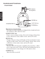
Controls and Functions
Front Panel
Microphone
Preamplifier
Controls and
Functions
SOUND LEVEL METER
NL-27
MODE key
START/STOP
MODE
A/C/CAL
A/C/CAL key
START/STOP key
MENU
POWER
POWER key
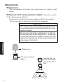
Microphone/preamplifier
Microphone and preamplifier are integrated in a single enclosure.
An extension cable cannot be used.
START/STOP key
Press to start or stop processing. Also used to change setting values
in the calibration screen, menu screen, and recall screen.
MODE key
Changes the processing result display in the measurement screen
and processing screen. Also used to change setting values in the
calibration screen, menu screen, and recall screen.
A/C/Cal key
This key selects the frequency weighting characteristics, calibration screen and recall screen. Pressing and holding this key in
the measurement screen changes it to the menu screen.
POWER key
Turns the unit on and off.
2
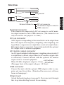
Side View
Strap mount
External connector
Controls and
Functions
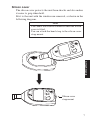
External connector
DC out connector
AC monitor output connector
USB connector
This connector is composed of a DC out connector, an AC monitor output connector, and a USB connector. (The connector can
only be used for one purpose at a time.)
DC out connector
A DC signal corresponding to the sound level can be output from
here. The signal after frequency weighting, time weighting, and
logarithmic compression is output here (constant output when a
DC output cable is connected). Connect the unit with the optional
DC output cable to external equipment.
AC monitor output connector
An AC signal weighted with frequency weighting characteristic Z
is output here (constant output when an AC monitor output cable
is connected). Connect the unit with the optional AC monitor
output cable to external equipment.
+600 mVrms
When 110 dB is displayed, output is 1 Vrms - 400 mVrms .
(The upper limit of the output voltage is 1.8 Vrms)
USB connector
Connect the unit with the optional USB adapter cable to computer and send stored data. (Download the necessary software
from our homepage.)
Strap mount
Attach the hand strap here (see page 8). Pass your wrist through
this strap when holding the unit for measuring.
3
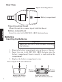
Rear View
Tripod mounting thread
Battery compartment
Tripod mounting thread
Mount the unit on a camera tripod with this thread.
Batteries
Battery compartment
Insert two size AAA (IEC R03, LR03) batteries here.
Batteries
Inserting the Batteries
Important
Make sure the unit is turn off before inserting
the batteries.
1. Remove the battery compartment cover on the rear of the unit.
2. Insert two size AAA (IEC R03, LR03) batteries into the
battery compartment. Insert correctly as indicated in the
compartment.
3. Replace the battery compartment cover.
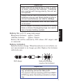
Press and pull in the arrow direction
Battery
contact
Remove the battery
compartment cover
4
Battery
contact
Insert two size AAA
(IEC R03, LR03) batteries
Important
Take care not to reverse the (+) and (-) polarity when inserting the batteries. If batteries
are inserted with wrong polarity, the unit will
not operate.
Always use two identical batteries, and replace
batteries only as a set. Mixing battery types or
old and new batteries can lead to damage.
Remove the batteries from the unit when it
is not used.
Do not subject the battery connectors to strong
force or stress. Damaged springs can lead to
loss of proper battery contact.
Manganese batteries: approx. 3 hours
Alkaline batteries:
approx. 9 hours
Battery life will be reduced by 20% when a DC output cable
is connected.
Batteries
Battery life (at 23°C, using wide range)
Battery indication
Indicates battery charge. When the indicator starts to flash, correct measurement is no longer possible. Replace the batteries
with fresh ones.
Full charge
Indicator flashing
(replace the batteries)
Important
If the indicator starts flashing during processing, processing will end at that point.
You cannot start processing with the START/
STOP key when the battery indication is flashing.
5
Attachments
Windscreen
We recommend attaching the windscreen to reduce wind
noise.
Windscreen fall out prevention rubber (hereafter called
“fall out prevention rubber”)
Prevents the windscreen from dropping off the microphone.
This is attached to the unit at the time of shipment.
Important
The windscreen can easily drop off the unit,
so we recommend attaching the fall out prevention rubber.
Be sure to follow the instructions in the following diagram when attaching or detaching
the fall out prevention rubber. Turning it in the
opposite direction may loosen the microphone
and cause it to fall off.
Attachments
Windscreen
Fall out prevention
rubber
Turn the fall out
prevention rubber
only in this direction.
SOUND LEVEL METER
6
NL-27
Silicon cover
The silicon cover protects the unit from shocks and also makes
it easier to grip when held.
Fit it to the unit with the windscreen removed, as shown in the
following diagram.
R
POWE
MODE
STOP
START/
D LEVE
SOUN
L METE
R
NL-27
L
A/C/CA
MENU
Note
You cannot use external connector when the silicon
cover is fitted.
You can attach the hand strap to the silicon cover
strap mount.
MENU
POWER
A/C/CAL
MODE
START/STOP
SOUND LEVEL METER
NL-27
Attachments
Silicon cover
strap mount
7
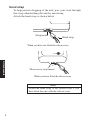
Hand strap
To help prevent dropping of the unit, pass your wrist through
this strap when holding the unit for measuring.
Attach the hand strap as shown below.
Strap mount
Hand strap
When you have not fitted the silicon cover
POWER
Attachments
Silicon cover strap mount
When you have fitted the silicon cover
Note
Attach the hand strap to the silicon cover if you
have fitted the unit with the silicon cover.
8
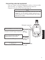
Connecting external equipment
You can connect external equipment, such as a data recorder,
level recorder, or computer, to the external connector.
Connect as shown in the following diagram.
Note
The connector has the ability to act as a DC out
connector, an AC monitor output connector, or a
USB connector, but it can perform only one of these
functions at a time.
External connector
SOUND LEVEL METER
Data recorder DA-20 or DA-40 etc.
NL-27
DC output
CC-98D
START/STOP
MODE
A/C/CAL
MENU
POWER
Data recorder DA-20 or DA-40,
analyzer SA-01 or SA-78 etc.
AC monitor
NL-27
Attachments
(Connect to the DC input connector) cable
(Connect to the AC input connector) output cable
CC-98A
A computer etc.
(Connect to the USB connector)
USB adapter cable
CC-98S
9
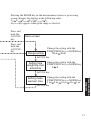
State transition diagram (functions and operation
keys)
Startup
Power on
Measurement
screen
Processing
screen
START/STOP key
Frequency weighting characteristic
A
START/STOP key, or
after the measurement
time has elapsed
A/C/Cal key
Frequency weighting characteristic
C
A/C/Cal key
Calibration
screen
Internal calibration
A/C/Cal key
State transition
diagram
External calibration
Reduce volume with
the START/STOP key
Raise volume with
the MODE key
A/C/Cal key
Recall screen
A/C/Cal key
10
Move the address
down with the
START/STOP key
Move the address up
with the MODE key
Pressing the MODE key in the measurement screen or processing
screen changes the display in the following order.
Lp Leq Lmax LE( LCpeak) Lp
LCpeak only appears when peak range is selected.
Press and
hold the
A/C/CAL
key
Press and
hold the
A/C/CAL
key
Menu screen
Change the setting with the
START/STOP key or MODE key
Range setting
Wide Peak
A/C/Cal key
Change the setting with the
Setting time
weighting char- START/STOP key or MODE key
F S
acteristics
A/C/Cal key
Change the setting with the
START/STOP key or MODE key
1 m 5 m 10 m 1 h 1 m
A/C/Cal key
State transition
diagram
Setting measurement time
11
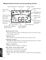
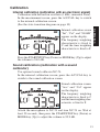
Measurement screen and processing screen
Measurement time Elapsed time
Address number
Processing
mark
Sound level
under range
indication
Battery indication
Bar graph, level range scale
Sound level
overload indication
Processing reProcessing result under range
sult overload
Processing reindication
indication
sult symbol
Level indication
Time weighting
Frequency weighting
characteristics
characteristics
Measurement time
The measurement time set in the menu screen (see state transition diagram, page 11).
Elapsed time
The amount of time elapsed since processing started.
Address number
The address where the processing result (the next process result
in the measurement screen) is stored.
Battery indication
Indicates battery charge. (see page 5)
Measurement
screen
Bar graph, level range scale
Shows the sound level in a bar graph.
Sound level overload indication
Shows that the sound level has exceeded the measurement
range.
12
Processing result overload indication
Appears during processing when the sound level exceeds the
measurement range, and remains until the next process starts
(when a processing result is shown).
Level indication
Shows the sound level (L p) and each processing result (L eq,
L max , L E , and L Cpeak) as digits. Switch the display with the
MODE key.
L Cpeak is processed and shown only when peak range (see page
16) is selected.
Time weighting characteristics
Shows the time weighting characteristics selected in the menu
screen.
Processing result symbol
Shows the relevant symbol for the displayed processing result
(L eq, L max, L E , or L Cpeak).
Frequency weighting characteristics
Change with the A/C/CAL key. See the state transition diagram
(page 10).
Processing result under range indication
If the sound level falls below the measurable limit (-0.6 dB) during processing, this appears until the next process starts (when
a processing result is shown).
Sound level under range indication
Appears when the sound level falls below the measurable limit
(-0.6 dB).
Processing mark
Flashes during processing.
Measurement
screen
13
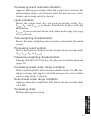
Power/
Measuring
Power on and off
Press the POWER key for 0.5 seconds or more to turn the power
on or off.
Measurement
Selecting frequency weighting characteristics
In the measurement screen, press the A/C/CAL key to select
either frequency weighting characteristic A or C. (See the state
transition diagram on page 10)
Processing (measurement)
Press the START/STOP key to start the processing.
The processing mark flashes during processing. Additionally,
pressing the MODE key switches the display to show processing
results (L p, L eq, L max, L E , or L Cpeak) made up to that point.
Processing stops when the measurement time elapses or you
press the START/STOP key.
Storing processing data
When processing stops, the L eq, L max, L E , or L Cpeak processing results are automatically stored, and the address number
increases by one.
14
Calibration
Internal calibration (calibration with an electronic signal)
Calibration with the built-in oscillator (1 kHz, sinusoidal wave).
In the measurement screen, press the A/C/CAL key to switch
to the internal calibration screen.
(See the state transition diagram on page 10)
Calibration
Internal calibration screen
“Int”, “Cal”, and “94.0dB”
appear on the display.
The frequency weighting
characteristic is fixed to
C and the time weighting
characteristic is fixed to F.
Press the START/STOP key (Down) or MODE key (Up) to adjust
the volume to 94.0 dB.
Sound calibration (calibration with a sound
calibrator)
Use optional sound calibrator NC-74.
In the internal calibration screen, press the A/C/CAL key to
switch to the sound calibration screen.
Sound calibration screen
“Aco” and “Cal” appear
on the display.
The frequency weighting
characteristic is fixed to C
and the time weighting characteristic is fixed to F.
Attach the microphone to NC-74 and turn NC-74 on. Wait at
least 30 seconds, then press the START/STOP key (Down) or
MODE key (Up) to adjust the volume to 93.9 dB.
15
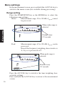
Menu settings
In the measurement screen, press and hold the A/C/CAL key to
switch to the menu screen (not available during processing).
Range setting
Press the START/STOP key or the MODE key to select the
following range settings.
Wide:
Measurement range: 30 to 130 dB, L Cpeak cannot
be processed
When wide range is
selected
Menu settings
Flashes every
0.5 seconds
Peak:
Measurement range: 65 to 130 dB, L Cpeak can be
processed
Even if the frequency weighting characteristic is
A, L Cpeak is processed as C.
When peak range is
selected
Flashes every
0.5 seconds
Press the A/C/CAL key to switch to the time weighting characteristic settings.
Press and hold the A/C/CAL key to return to the measurement
screen.
16
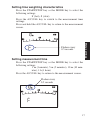
Setting time weighting characteristics
Press the START/STOP key or the MODE key to select the
following settings.
F (fast), S (slow)
Press the A/C/CAL key to switch to the measurement time
settings.
Press and hold the A/C/CAL key to return to the measurement
screen.
Menu settings
Flashes every
0.5 seconds
Setting measurement time
Press the START/STOP key or the MODE key to select the
following settings.
1 m (1 minute), 5 m (5 minutes), 10 m (10 minutes), 1 h (1 hour)
Press the A/C/CAL key to return to the measurement screen.
Flashes every
0.5 seconds
17
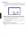
Sleep mode
With the measurement screen being shown and no key is pressed
for 10 minutes, the unit enters sleep mode and the sleep mode
screen appears. Power consumption is 30% of normal in sleep
mode.
Menu settings
Situations where the unit will not enter sleep mode
The unit will not enter sleep mode in the following situations,
even if no key is pressed for 10 minutes.
If the processing screen, calibration screen, recall screen, or
menu screen is displayed.
If a cable is connected to the external connector (any one of
the three types).
Waking the unit from sleep mode
Press any key in sleep mode to return to the measurement
screen.
18
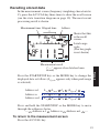
Recalling stored data
In the measurement screen (frequency weighting characteristic
C), press the A/C/CAL key three times to show the recall screen
(see the state transition diagram on page 10). The most recent
processing result is shown.
Measurement time Elapsed time
Address
Shows that this
is the recall
screen.
Level range
scale
(The bar graph
is not shown)
Measurement result
("--.-" appears if no data has been
stored)
Address n-1
L eq
L max
LE
(L Cpeak)
Address n
L eq
L max
LE
(L Cpeak)
Address n+1
L eq
L max
LE
(L Cpeak)
Recall
Press the START/STOP key or the MODE key to change the
displayed data as follows (L Cpeak appears only when peak range
is selected).
Press and hold the START/STOP or the MODE key to move
through the addresses faster.
--- Address n-1 Address n Address n+1 ---
To return to the measurement screen
Press the A/C/CAL key
19
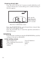
Clearing stored data
Press the A/C/CAL key for 3 or more seconds while the recall
screen is shown and a screen asking you to confi rm clearing of
the data appears.
ALL and CLr
flash alternately
on the screen every 0.5 seconds.
Data clear confi rmation screen
Press the START/STOP key and all stored data is cleared, then
the recall screen appears again.
Press the A/C/CAL key to cancel the operation and return to
the recall screen.
Initializing
Power the unit on while pressing the START/STOP key and the
settings in the unit are initialized.
Initial setting values
Initializing
Measurement time
Time weighting characteristics
Level range
Address
20
10 m (10 minutes)
F (Fast)
Wide
1
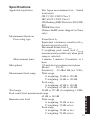
Specifications
Applicable legislation
The Japan measurement law - Sound
level meter
JIS C 1509-1:2005 Class 2
IEC 61672-1:2002 Class 2
CE Marking (EMC Directive 2004/108/
EC)
WEEE Directive
Chinese RoHS (units shipped to China
only)
Measurement functions
Processing type
Specifi cations
Sound level L p
Equivalent continuous sound level L eq
Sound exposure level L E
Maximum Sound level L max
C weighting peak sound level L Cpeak
(measurement possible only when peak
range is selected)
Measurement times
1 minute, 5 minutes, 10 minutes, or 1
hour
1/2-inch electret condenser microphone
Microphone
Model:
UC-52
Sensitivity: -33 dB±3 dB (re.1 V/Pa)
Measurement level range
Wide range
A weighting: 30 dB to 130 dB
C weighting: 36 dB to 130 dB
Peak range
A weighting: 65 dB to 130 dB
C weighting: 65 dB to 130 dB
Total range
30 dB to 137 dB (A weighting, 1 kHz)
Peak sound level measurement range
65 dB to 140 dB
Inherent noise level
Wide range
A weighting: 24 dB or less
C weighting: 30 dB or less
Peak range
A weighting: 59 dB or less
C weighting: 59 dB or less
21
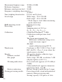
Specifi cations
Measurement frequency range 20 Hz to 8 kHz
Reference frequency
1 kHz
Reference sound pressure level 94 dB
Frequency weighting characteristics
A and C
Time weighting characteristics F (fast) and S (slow)
Level range
Wide range 30 to 130 dB
Peak range* 65 to 130 dB
* Peak range is used when measuring
peak sound level.
RMS detecting circuit
Digital processing
Processing
Digital
Sampling interval: 30.3 µs
(L p, L eq, L max, L E , L Cpeak)
Calibration
Calibration frequency: 1 kHz
Calibration sound pressure level:
94 dB
The Japan measurement law:
Electronic calibration using an internal electronic signal
JIS, IEC:
sound calibration using NC-74
Windscreen
Conforms to JIS C 1509-1 Class 2 and
IEC 61672-1 Class 2 even when the
windscreen is attached
Display
TN positive display, reflective type
Numeric readout
0.1 dB resolution
Bar graph
Scale range 100 dB, resolution 5 dB
(display update cycle 0.1 s)
Warning indications
Over (overload): appears at 137.4 dB (at
1 kHz)
Under (underload): appears at measurement lower limit, -0.6 dB
Battery indication
Battery charge is indicated in 3 stages
Storing processing results
Processing results stored in the internal
memory when processing ends.
Storing capacity: 199 pieces of data
22
Specifi cations
Stored data can be viewed in the recall
screen. The stored data can also be sent
to a computer through an optional USB
adapter cable.
DC out connector
DC output: 3 V (full scale), 25 mV/dB
Output impedance: 50 Ω
Load impedance: 10 kΩ or more
AC monitor output connector AC output:
+600 mVrms
1 Vrms
(at 110 dB)
-400 mVrms
(Upper limit: 1.8 Vrms)
Overload:
+2 dB
Output impedance: 600 Ω
Load impedance: 10 kΩ or more
Frequency weighting characteristics:
Z weighting
USB connector
Use an optional USB adapter cable to
send stored data to a computer.
2 size AAA (IEC R03, LR03) batteries
Power requirements
Power consumption:
Approx. 80 mA (when operating at 3 V)
(Approx. 30% in sleep mode)
Battery life (at normal temperature):
Wide range
Approx. 9 hours (using alkaline
batteries)
Approx. 3 hours (using manganese batteries)
Peak range
Approx. 7 hours (using alkaline
batteries)
Approx. 2 hours (using manganese batteries)
Battery life will be reduced by 20% when
a DC output cable is connected.
Power consumption increases by approximately 20% during calibration.
23
Environmental conditions for operation
-10°C to 50°C, 10% to 90% R.H. (No
condensation)
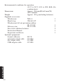
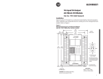
Dimensions
Approx. 120 mm(H)×63 mm(W)
×23.5 mm(D)
Weight
Approx. 105 g (including batteries)
Supplied accessories
Windscreen
WS-14
1
Hand strap
VM-63-017
1
Windscreen fall out prevention rubber
NL-27-014
1
Silicon cover
NL-27-026
1
Size AAA alkaline batteries
2
Instruction Manual
1
Inspection certificate
1
Optional equipments
Sound calibrator
NC-74
AC monitor output cable
CC-98A
DC output cable
CC-98D
USB adapter cable
CC-98S
Specifi cations
24
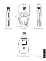
23.5
120
63
SOUND LEVEL METER
START/STOP
MODE
NL-27
A/C/CAL
MENU
POWER
Left Side View
Front View
Right Side View
Dimensional Drawings
Unit: mm
Specifi cations
Rear View
25
Description
for IEC
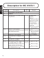
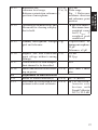
Description for IEC 61672-1
Standard
See
Description
paragraph
also
5
Performance specifications
5.1
General
5.1.4
Configuration & normal mode 9.2.1 b)
of operation
5.1.6
Models of microphone
9.2.1 c)
Appropriate procedures for use 9.2.5 b)
the sound level meter
5.1.7
5.1.8
Mounting of microphone
Identification of computer software
Description of frequency weightings that are provided
Description of level ranges (@
A-weighted SPL @ 1 kHz )
Instruction manual of the level
range controls and function.
Recommendation for selecting
the optimum level range.
5.1.10
5.1.12
26
9.2.1 b)
Remark
Configuration
• NL-27
• WS-14
• Windscreen fall out
prevention rubber
• Silicon cover (
Attachments)
Nor mal mode of
operation
Power on and off
Unit powered
UC-52
Power on and off,
Me a su r ement ,
Calibration
Attachments
N/A
9.2.2 c)
A, C
9.2.2 h)
9.2.5 c)
30 dB to 137 dB
Menu settings
Menu settings
5.1.13
5.1.15
5.1.16
5.1.17
5.1.18
5.2
5.2.1
5.2.3
27
Description
for IEC
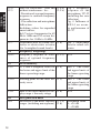
5.1.14
Reference SPL
9.2.5 a), 94.0 dB
reference level range,
9.3 a), b), Wide range
Reference orientation, reference c)
Fig. 1 Reference
position of microphone.
incidence direction
and reference point
position
Operating of the hold facility and
Mea su rement:
the means for clearing a display
Maximum timethat is held.
weighted sound
level L m a x , C
weighted peak
sound level
Dummy microphone: Design 9.3 g)
Capacit a nce of
goal and tolerance
dummy microphone:
19 pF
Tolerance: ±3 pF
Highest SPL and Peak-Peak 9.3 i)
150 dB
input voltage without causing
28 Vp-p
damage.
Characteristics of each indepenN/A
dent channel to be described
Initial time interval after switch- 9.2.5 e) Less than 1 mining on power
utes.
Adjustment to indicated levels
Model of sound calibrator(s)
9.2.4 a) NC-74 (RION)
Procedure for calibration & ad- 9.2.4 c)
Calibration:
justment with sound calibrator
Acoustic calibration wit h
Sound Calibrator
NC-74, 93.9 dB
5.2.4
5.2.5
Description
for IEC
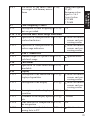
5.2.7
5.4
5.4.12
5.5
5.5.9
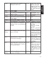
Data for correction - with and
without windscreen - for :
- Deviation of average frequency
response to uniform frequency
response.
- Case reflection and microphone
diffraction
Including values for expanded
uncertainties.
In 1/3 octave frequencies for 63
Hz to 1 kHz and 1/12 octave frequencies for 1 kHz to 16 kHz
Adjustment data for sound calibrator or electrostatic actuator
(for A-weighted sound levels)
Frequency weightings
Frequency response & tolerances of optional frequency
responses
Level linearity
A, C and Z weighted levels for
the lower and upper limit of the
linear operating range.
9.2.4 d)
9.2.5 b)
Fig. 2 Frequency
resp on se of t he
microphone UC-52
(including the case
reflection)
Fig. 4 Influence of
WS-14 on acoustic performance of
NL-27
9.3 d)
Tab. 2 Adjustment
data for sound calibrator
9.2.2 c)
N/A
9.3 e)
Tab. 3 The lower
and upper limits of
the linear operating
range
Tab. 3 The lower
and upper limits of
the linear operating
range
N/A
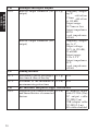
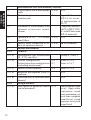
5.5.10
Starting point for the level lin- 9.3 f)
earity error
5.5.11
How to test level linearity if dis- 9.3 k)
play range < linearity range
Self generated noise
Self-noise at the more sensitive 9.2.5 o)
ranges (including microphone) 9.3 h)
5.6
5.6.1
28
Maximum value
A: <24 dB
C: <30 dB
5.6.3
Dummy microphone
(19 pF)
Maximum value
Equal to 5.6.1
Typical value
A: 19 dB
C: 24 dB
5.7
5.7.1
Time weighting F and S
Description of time weightings 9.2.2 d) F, S
that are provided
5.10 - 5.11 Overload and Under-range indication
5.10.1
Operation & interpretation of 9.2.5 k)
Measurement
overload indicators
screen and processing screen
5.11.1
Operation & interpretation of
Measurement
under-range indicators
screen and processing screen
5.12
Peak C sound level
5.12.1
Nominal range of LCpeak at for 9.2.2 i)
Specifications
each level range
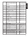
5.14
Thresholds
5.14
Operation of user-selectable 9.2.5 l) N/A
thresholds
5.15
Display
5.15.2
Description of the indication of 9.2.2 g)
Measurement
displayed quantities
screen and processing screen
5.15.3
Description of the display
9.2.2 g)
Measurement
screen and processing screen
5.15.4
Description of the displayed 9.2.2 a) N/A
quantities
5.15.5
Statement of the display update 9.2.2 g) 1 second
rate
5.15.6
Time interval for completion of 9.2.5 f) N/A
the integration
5.15.7
Description of method for trans- 9.2.5 m)
Attachments
ferring data to PC
29
Description
for IEC
Self-noise at the more sensi- 9.3 h)
tive ranges with dummy microphone
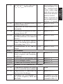
5.16
5.16.1
Description
for IEC
Analogue and digital outputs
Electric output connector (AC 9.2.5 p)
output)
Electric output connector (DC
output)
5.17
5.17.1
5.17.2
5.18
5.18.1
30
Frequency weighting: Z
+600 mVrms
1 Vrms -400 mVrms
(at 110 dB)
Output range:
1.8 Vrms or less
Output impedance:
600 Ω
Load impedance:
>10 kΩ
Frequency weighting: A, C
Output voltage:
3.0 V (at 130 dB),
25 mV/dB
Output range:
0.5 to 3.2 V
Output impedance:
50 Ω
Load impedance:
>10 kΩ
Timing facilities
Procedure to preset the integra- 9.2.5 g) N/A
tion time & time of the day
Statement of the minimum & 9.2.5 h) N/A
maximum integration time
RF emissions and power supply disturbance
Length & type of interface cable 9.2.5 n) AC monitor output
and characteristics of connected
cable CC-98A (2 m)
devices
DC output cable
CC-98D (2 m)
USB adapter cable
CC-98S (2.5 m)
All cables shielded
5.18.2
Operating mode or highest radio 9.3 n)
frequency emissions
USB adapter cable
CC-98S (with ferrite
5.20
5.20.2
5.20.3
5.20.4
5.20.5
6
6.1.2
6.2.2
(Note)
6.5.2
6.6.1
cores)
Power supply
Maximum and minimum power 9.3 j
Maximum: 3.6 V
supply voltage
Minimum: 1.8 V
Battery types & battery life
9.2.3 a) Batteries
Operation from an external 9.2.3 c) N/A
power supply
Public power supply voltage
9.2.3 d) N/A
Environmental, electrostatic and radio frequency criteria
Time interval for needed to 9.3 l)
Temperature change:
stabilize after environmental
< 1 hour
changes
Humidity change:
< 1 hour
Static pressure
change: < 5 minutes
Measurement when static presCalibration and measure is < 85 kPa
surement performed
in this environment
using Sound Calibrator NC-74
Degradation of functions by 9.2.7 b) Measurement value
electrostatic discharge
affected temporarily by electrostatic
discharge
Operating mode with least im- 9.3 o)
Fig. 5
munity to AC power frequency
Operation mode:
fields and RF fields
normal operation
Connection pattern:
USB adapter cable
CC-98S (with ferrite
6.6.4
(Note)
Field strength for conforming 9.3 m)
(in case > 10 V/m)
cores)
N/A
31
Description
for IEC
Operation mode:
normal operation
Connection pattern:
7
7.1
Description
for IEC
7.2
7.3
7.4
7.5
9
9.2.1
9.2.1 a)
9.2.1 b)
9.2.1 c)
9.2.1 d)
9.2.1 e)
9.2.2
9.2.2 a)
32
Provisions for use with auxiliary devices
Correction for use of microphone 9.2.6 b) N/A
cable
Effect of optional accessories 9.2.6 a) Fig. 4 Influence of
(windscreen)
WS-14 on acoustic performance of
NL-27
Statement of conformance with
Compliant with IEC
optional accessories (wind61672-1 (JIS C 1509screen)
1), with Windscreen
WS-14 mounted
Operation of 1/1 - 1/3 octave 9.2.6 c) N/A
band fi lters
Details about connection & ef- 9.2.6 d)
Attachments
fects of auxiliary devices
Instruction manual
General
Description of type, classification
Group X, Class 2
(X, Y, Z) and class
Overall configuration,
5.1.4
Refer to 5.1.4
Normal operation configuration 5.1.7
Refer to 5.1.7
(including windscreen)
Models of microphones
5.1.6
Refer to 5.1.6
Required microphone cable to
N/A
conform
Characteristics & operation each
N/A
channel
Design features
Description of quantities which 5.15.4
time-weighted sound
can be measured
level, equiva lent
continuous sound
level, maximum value of time-weighted
sound level, sound
exposure level, peak
sound level
Relative free-field response as
function of incidence angle and
frequency (detailed tabular description)
9.2.2 c)
Description of the frequency 5.1.10
weightings
5.4.12
Description of the time weight- 5.7.1
ings
Identification of the level ranges 5.1.12
(A-weighted @ 1 kHz)
Operation of the level range 5.1.12
control
Description of the display and 5.15.2-3update rates
4-5
Total range of A- weighted SPL 5.1.12
(@ 1 kHz)
Nominal range of L Cpeak at for 5.12.1
each level range
Computer software to operate 5.1.8
the SLM
Design goals and tolerances
for quantities which are not in
the standard (T-weight 10 ms,
L AIeq)
Power supply
Battery types & battery life
5.20.3
Description of the function of
battery check
Operation from an external 5.20.4
power supply
Public power supply voltage
5.20.5
Adjustment to indicated levels
Model of sound calibrator(s)
5.2.1
Calibration check frequency
Procedure for calibration & ad- 5.2.3
justment with sound calibrator
9.2.2 d)
9.2.2 e)
9.2.2 f)
9.2.2 g)
9.2.2 h)
9.2.2 i)
9.2.2 j)
9.2.2 k)
9.2.3
9.2.3 a)
9.2.3 b)
9.2.3 c)
9.2.3 d)
9.2.4
9.2.4 a)
9.2.4 b)
9.2.4 c)
Directional Characteristics with Horizont a l Di rect ion
(Fig. 6), Vertical
Direction (Fig. 7)
Refer to 5.1.10
Refer to 5.4.12
Refer to 5.7.1
Refer to 5.1.12
Refer to 5.1.12
Refer to 5.15.2-34-5
Refer to 5.1.12
Refer to 5.12.1
Refer to 5.1.8
N/A
Refer to 5.20.3
Batteries: Display
Refer to 5.20.4
Refer to 5.20.5
Refer to 5.2.1
1 kHz
Refer to 5.2.3
33
Description
for IEC
9.2.2 b)
9.2.4 d)
Description
for IEC
9.2.5
9.2.5 a)
9.2.5 b)
9.2.5 c)
9.2.5 e)
9.2.5 f)
9.2.5 g)
9.2.5 h)
9.2.5 i)
34
Data for correction - with and 5.2.4 5.2.5
without windscreen - for :
- Deviation of average frequency
response to uniform frequency
response.
- Case reflection and microphone
diffraction
Including values for expanded
uncertainties.
In 1/3 octave frequencies for 63
Hz to 1 kHz and 1/12 octave frequencies for 1 kHz to 16 kHz
Operating the sound level meter
Reference direction
5.1.13
Procedure to measure sound, 5.1.6
Influence of the instrument case 5.2.4
and operator.
5.2.5
Recommendation for selecting 5.1.12
optimum level range
Initial time interval after switch- 5.1.18
ing on power
Time interval for completion of 5.15.6
the integration
Procedure to preset the integra- 5.17.1
tion time & time of the day
Statement of the minimum & 5.17.2
maximum integration time
Operation of the “Hold” function
Refer to 5.2.4 5.2.5
Refer to 5.1.13
Refer to 5.1.6
Refer to 5.2.4
Refer to 5.2.5
Refer to 5.1.12
Refer to 5.1.18
Refer to 5.15.6
Refer to 5.17.1
Refer to 5.17.2
Mea su rement:
Measurement of
maximum timeweighted sound
level
Operation of the reset function or
L eq, L E , L peak and overload
9.2.5.k)
Operation & interpretation of 5.10.1
overload indicators
Operation of user-selectable 5.14
thresholds
Description of method for trans- 5.15.7
ferring data to PC
Length & type of interface cable 5.18.1
and characteristics of connected
devices
Self-noise at the more sensitive 5.6.1
ranges (including microphone).
Averaging time ≥ 30 s.
Characteristics of AC and DC 5.16.1
output
Accessories
Effect of windscreen (direc- 7.2
tional response and frequency
weighting)
Corrections for microphone cable 7.1
Use of bandpass fi lters
7.4
Connection of auxiliary devices 7.5
Influence of environmental conditions
Components intended for operation in controlled environment
Degradation of functions by 6.5.2
electrostatic discharge
Statement for conformance to
AC power frequency fields and
RF fields
9.2.5 l)
9.2.5 m)
9.2.5 n)
9.2.5 o)
9.2.5 p)
9.2.6
9.2.6 a)
9.2.6 b)
9.2.6 c)
9.2.6 d)
9.2.7
9.2.7 a)
9.2.7 b)
9.2.7 c)
Measurement results
(measurement values, overload indication, under-range
indication) are reset
when a new measurement is started.
Time required for
measurement initialization: < 1 second
Refer to 5.10.1
Refer to 5.14
Refer to 5.15.7
Refer to 5.18.1
Refer to 5.6.1
Refer to 5.16.1
Refer to 7.2
Refer to 7.1
Refer to 7.4
Refer to 7.5
None
Refer to 6.5.2
Statement of conforming to the basic
statement (Tab. 1)
35
Description
for IEC
9.2.5 j)
Description
for IEC
9.3
9.3 a)
9.3 b)
9.3 c)
9.3 d)
9.3 e)
9.3 f)
9.3 g)
9.3 h)
9.3 i)
9.3 j)
9.3 k)
9.3 l)
9.3 m)
9.3 n)
9.3 o)
36
Information for testing
Reference sound pressure level
Reference level range
Microphone reference point
For A-weighted sound levels:
Adjustment data for multi-frequency sound calibrator and/or
electrostatic actuator
Nominal A-weighted sound levels at the upper and lower limits
of the linear operating range on
each level range.
- For frequencies 31.5 Hz, 1, 4,
8 and 12.5 kHz
Starting point for the level linearity error
- For frequencies 31.5 Hz, 1, 4,
8 and 12.5 kHz
- At the reference level range
Dummy microphone: Design
goal and tolerance
Self-noise at the more sensitive
ranges with microphone and with
dummy microphone
Highest SPL and Peak-Peak input
voltage to accommodate
Maximum and minimum power
supply voltage
How to test level linearity if display range < linearity range
Time interval for needed to stabilize
after environmental changes
Field strength for conforming
(in case > 10 V/m)
Operating mode or highest radio
frequency emissions
Operating mode with least immunity to AC power frequency
fields and RF fields
5.1.13
5.1.13
5.1.13
5.2.7
Refer to 5.1.13
Refer to 5.1.13
Refer to 5.1.13
Refer to 5.2.7
5.5.9
Refer to 5.5.9
5.5.10
Refer to 5.5.10
5.1.15
Refer to 5.1.15
5.6.1 /
5.6.3
Refer to 5.6.1 /
5.6.3
5.1.16
Refer to 5.1.16
5.20.2
Refer to 5.20.2
5.5.11
Refer to 5.5.11
6.1.2
Refer to 6.1.2
6.6.4
Refer to 6.6.4
5.18.2
Refer to 5.18.2
6.6.1
Refer to 6.6.1
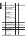
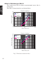
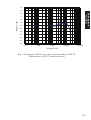
IEC61672-1 (JIS C 1509-1) Frequency Response
63
80
100
125
160
200
250
315
400
500
630
800
1000
1060
1120
1180
1250
1320
1400
1500
1600
1700
1800
1900
2000
2120
2240
2360
2500
2650
2800
3000
3150
3350
3550
63.10
79.43
100.0
125.9
158.5
199.5
251.2
316.2
398.1
501.2
631.0
794.3
1000.0
1059.3
1122.0
1188.5
1258.9
1333.5
1412.5
1496.2
1584.9
1678.8
1778.3
1883.6
1995.3
2113.5
2238.7
2371.4
2511.9
2660.7
2818.4
2985.4
3162.3
3349.7
3548.1
0.0
0.0
0.0
0.0
0.0
0.0
0.0
0.0
0.0
0.0
0.0
0.0
0.0
0.0
0.0
0.0
0.0
0.0
0.0
0.1
0.1
0.1
0.1
0.1
0.2
0.2
0.2
0.2
0.3
0.3
0.3
0.4
0.4
0.4
0.4
"NL-27
Frequency
Response
(dB)
case reflection"
0.0
0.0
0.0
0.0
0.0
0.0
0.0
0.0
0.0
0.0
0.0
0.0
0.2
0.3
0.3
0.3
0.3
0.3
0.3
0.3
0.3
0.2
-0.1
-0.1
-0.1
-0.1
0.0
0.0
-0.1
-0.3
-0.6
-0.8
-0.8
-0.6
-0.4
"NL-27 "Total
Electrical Response
Response (dB)"
(dB)"
-0.1
-0.1
-0.1
0.0
0.1
0.1
0.1
0.1
0.1
0.0
0.1
0.0
0.0
0.0
0.0
0.0
0.0
0.0
0.0
0.0
0.0
0.0
0.0
0.0
0.0
0.0
0.0
0.0
-0.1
-0.1
-0.1
-0.1
-0.1
-0.1
-0.1
-0.1
-0.1
-0.1
0.0
0.1
0.1
0.1
0.1
0.1
0.0
0.1
0.0
0.2
0.3
0.3
0.3
0.3
0.3
0.3
0.4
0.4
0.3
0.0
0.0
0.1
0.1
0.2
0.2
0.1
-0.1
-0.4
-0.5
-0.5
-0.3
-0.1
"Wind
screen
effect
(dB)"
0.0
0.0
0.0
0.0
0.0
0.0
0.0
0.0
0.0
0.0
0.0
0.0
-0.1
0.0
-0.1
0.0
-0.1
0.0
0.1
0.0
0.0
-0.1
0.1
0.1
0.1
0.2
0.2
0.1
0.2
0.2
0.2
0.2
0.2
0.3
0.4
"Total
"Total
Response expanded
uncertainty"
(WS-14
combined)
(dB)"
-0.1
-0.1
-0.1
0.0
0.1
0.1
0.1
0.1
0.1
0.0
0.1
0.0
0.1
0.3
0.2
0.3
0.2
0.3
0.4
0.4
0.4
0.2
0.1
0.1
0.2
0.3
0.4
0.3
0.3
0.1
-0.2
-0.3
-0.3
0.0
0.3
Description
for IEC
"Nominal "Exact
"UC-52
frequency frequency Frequency
(Hz)"
(Hz)"
Response
(dB)"
-0.1
-0.1
-0.1
0.0
0.1
0.1
0.1
0.1
0.1
0.0
0.1
0.0
0.1
0.3
0.2
0.3
0.2
0.3
0.4
0.4
0.4
0.2
0.1
0.1
0.2
0.3
0.4
0.3
0.3
0.1
-0.2
-0.3
-0.3
0.0
0.3
37
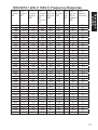
Description
for IEC
"Nominal "Exact
"UC-52
frequency frequency Frequency
(Hz)"
(Hz)"
Response
(dB)"
3750
4000
4250
4500
4750
5000
5300
5600
6000
6300
6700
7100
7500
8000
38
3758.4
3981.1
4217.0
4466.8
4731.5
5011.9
5308.8
5623.4
5956.6
6309.6
6683.4
7079.5
7498.9
7943.3
0.4
0.4
0.4
0.4
0.3
0.3
0.2
0.2
0.1
0.0
-0.1
-0.2
-0.4
-0.5
"NL-27
Frequency
Response
(dB)
case reflection"
-0.4
-0.5
-0.6
-0.3
0.1
0.5
0.2
0.0
-0.1
0.0
0.2
0.3
0.5
0.1
"NL-27 "Total
Electrical Response
Response (dB)"
(dB)"
-0.1
-0.1
-0.1
0.0
0.0
0.0
0.0
0.0
0.0
0.0
0.0
0.0
0.1
0.1
-0.1
-0.2
-0.3
0.1
0.4
0.8
0.4
0.2
0.0
0.0
0.1
0.1
0.2
-0.3
"Wind
screen
effect
(dB)"
0.3
0.4
0.4
0.5
0.4
0.4
0.4
0.5
0.5
0.5
0.3
0.3
0.3
0.2
"Total
"Total
Response expanded
uncertainty"
(WS-14
combined)
(dB)"
0.2
0.2
0.1
0.6
0.8
1.2
0.8
0.7
0.5
0.5
0.4
0.4
0.5
-0.1
0.2
0.2
0.1
0.6
0.8
1.2
0.8
0.7
0.5
0.5
0.4
0.4
0.5
-0.1
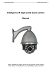
Reference incidence direction and reference point
position
Description
for IEC
Reference direction
of incidence
Reference point position
Center of diaphragm plane
Fig. 1 Reference incidence direction and reference point position
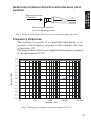
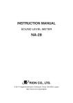
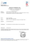
Frequency Response
The frequency response of a sound field microphone is expressed as the frequency response in the reference direction
of incidence (0º).
The diagram below shows an example for the frequency response
of the microphone UC-52.
3.0
2.5
2.0
Response (dB)
1.5
1.0
0.5
0.0
-0.5
-1.0
-1.5
-2.0
-2.5
-3.0
10
100
1 000
Frequency (Hz)
10 000
100 000
Fig. 2 Frequency response of the microphone UC-52
39
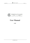
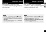
Effect of Windscreen WS-14
Description
for IEC
The windscreen WS-14 reduces measurement errors due to
wind noise.
The WS-14 characteristics are shown below.
Frequency weighting A
Wind noise level (dB)
130
120
NL-27
110
With WS-14
100
90
80
70
60
50
40
1
10
Wind velocity (m/s)
100
Frequency weighting C
Wind noise level (dB)
130
120
NL-27
110
With WS-14
100
90
80
70
60
50
40
1
10
Wind velocity (m/s)
Fig. 3 Wind noise reduction effect
40
100
3.0
2.5
Description
for IEC
2.0
1.5
Response (dB)
1.0
0.5
0.0
-0.5
-1.0
-1.5
-2.0
-2.5
-3.0
10
100
1 000
Frequency (Hz)
10 000
100 000
Fig. 4 Infl uence of WS-14 on acoustic performance of NL-27
(Referenced to NL-27 characteristics)
41
The greatest susceptibility configuration for radio
frequency fi elds
Description
for IEC
Ferrite cores
SOUND LEVEL METER
NL-27
Computer
START/STOP
MODE
A/C/CAL
MENU
CC-98S
POWER
NL-27
Polarization direction is
parallel to drawing plane
Antenna
Operation mode: normal operation
Connection pattern
- USB adapter cable (with ferrite cores) CC-98S 2.5 m
Fig. 5 The greatest susceptibility confi guration for radio frequency fi elds
42
Statement of conforming to the basic statement
Tab. 1 Statement of conforming to the basic statement
Description
for IEC
Immunity to AC power The specification of IEC 61672-1 Class 2 is
frequency fields
satisfied
Immunity to RF fields The specification of IEC 61672-1 Class 2 is
satisfied
Emissions
The specification of IEC 61672-1 Class 2 is
satisfied
Adjustment data for sound calibrator
Tab. 2 Adjustment data for sound calibrator
Frequency (Hz)
31.5
63
125
250
500
1000
2000
4000
8000
12500
16000
Correction (dB)
0.0
0.0
0.0
0.0
0.0
0.1
0.3
1.3
3.2
6.5
6.7
The lower and upper limits of the linear operating range
Tab. 3 The lower and upper limits of the linear operating range
A-weighting
Frequency (Hz)
Upper
Start
Lower
C-weighting
Sound level (dB)
31.5
1k
4k
8k
97.0 137.0 136.0 133.0
54.0 94.0 94.0 94.0
30.0 30.0 30.0 30.0
Sound level (dB)
Frequency (Hz) 31.5
1k
4k
8k
Upper
134.0 137.0 136.0 133.0
Start
94.0 94.0 94.0 94.0
Lower
36.0 36.0 36.0 36.0
43
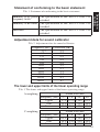
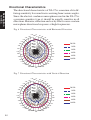
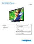
Directional Characteristics
Description
for IEC
The directional characteristics of NL-27 is a measure of its differing sensitivity for sound waves arriving from various angles.
Since the electret condenser microphone used in the NL-27 is
a pressure-sensitive type, it should be equally sensitive in all
directions. However, refraction and cavity effects cause a certain
microphone directional response at high frequencies.
Fig. 6 Directional Characteristics with Horizontal Direction
350° 0°
5dB
330°
320°
310°
340°
10° 20°
0dB
30°
40°
50°
-5dB
300°
60°
-10dB
500 Hz
70°
290°
-15dB
280°
80°
90°
270°
100°
260°
250°
110°
240°
120°
230°
220°
210°
200°190°
180°
1 kHz
2 kHz
4 kHz
8 kHz
16 kHz
130°
140°
150°
170°160°
Fig. 7 Directional Characteristics with Vertical Direction
350° 0°
5dB
330°
320°
310°
300°
340°
0dB
-5dB
-10dB
290°
10° 20°
30°
40°
50°
60°
280°
80°
270°
90°
100°
260°
250°
110°
240°
120°
230°
220°
210°
200°190°
180°
44
500 Hz
70°
-15dB
130°
140°
150°
170°160°
1 kHz
2 kHz
4 kHz
8 kHz
16 kHz
45
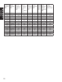
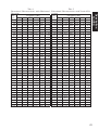
Description
for IEC
Tab. 4
Tab. 5
Directional Characteristics with Horizontal Directional Characteristics with Vertical DiDirection
rection
Frequency [Hz]
Frequency [Hz]
AnAngle 501 1000 1995 3981 7499 15849
gle 501 1000 1995 3981 7499 15849
0
0
0
0
0
0
0
0
0
0
0
0
0º
0º
10º -0.07 -0.01 -0.08 -0.03 -0.05 -0.23
10º -0.02 0.00 -0.05 0.06 0.10 -0.40
20º -0.07 -0.06 -0.07 -0.06 -0.15 -0.78
20º -0.01 -0.03 -0.04 0.01 0.06 -0.74
30º -0.02 -0.07 -0.04 -0.13 -0.19 -0.87
30º -0.02 -0.09 -0.08 -0.06 -0.21 -1.03
40º -0.04 -0.17 -0.04 -0.32 -0.46 -1.15
40º -0.04 -0.11 -0.05 -0.27 -0.66 -1.46
50º -0.10 -0.28 -0.08 -0.57 -0.81 -1.98
50º -0.08 -0.12 -0.07 -0.59 -0.86 -2.44
60º -0.09 -0.33 -0.01 -0.66 -1.38 -3.46
60º -0.13 -0.22 0.00 -0.89 -1.63 -3.57
70º -0.18 -0.46 -0.05 -0.46 -2.14 -4.94
70º -0.12 -0.31 0.12 -0.76 -2.52 -4.25
80º -0.19 -0.58 0.06 -0.26 -2.98 -5.75
80º -0.18 -0.47 0.06 -0.16 -3.09 -6.70
90º -0.22 -0.81 -0.01 -0.12 -3.94 -6.52
90º -0.14 -0.57 0.27 -0.57 -3.85 -7.44
100º -0.17 -0.80 -0.10 -0.32 -3.65 -6.83 100º -0.25 -0.73 -0.33 -0.65 -3.75 -7.25
110º -0.19 -0.87 -0.38 -0.61 -2.87 -9.21
110º -0.21 -0.83 -0.57 0.11 -4.02 -8.42
120º -0.21 -0.86 -0.82 -0.55 -3.07 -9.07 120º -0.18 -0.86 -0.86 0.20 -3.07 -8.93
130º -0.19 -0.84 -1.04 -0.51 -3.22 -7.88 130º -0.18 -0.85 -1.28 -0.35 -3.81 -9.82
140º -0.18 -0.75 -1.20 -1.09 -3.84 -8.54 140º -0.16 -0.81 -1.28 -1.36 -2.55 -8.96
150º -0.16 -0.70 -1.03 -1.49 -3.89 -9.86 150º -0.13 -0.78 -1.06 -1.98 -3.38 -10.66
160º -0.18 -0.64 -0.85 -1.37 -4.61 -10.87 160º -0.13 -0.70 -0.79 -1.42 -6.17 -7.11
170º -0.16 -0.57 -0.59 -0.75 -4.15 -9.62 170º -0.14 -0.62 -0.52 -0.40 -3.96 -12.72
180º -0.14 -0.56 -0.43 -0.24 -2.77 -8.17 180º -0.11 -0.57 -0.34 -0.28 -3.15 -8.29
190º -0.17 -0.57 -0.53 -0.70 -4.09 -9.28 190º -0.12 -0.54 -0.55 -0.32 -4.02 -10.20
200º -0.19 -0.57 -0.61 -0.71 -4.21 -9.72 200º -0.12 -0.59 -0.73 -0.95 -6.61 -9.93
210º -0.14 -0.66 -0.73 -1.56 -4.68 -9.87 210º -0.16 -0.70 -1.11 -1.98 -3.50 -10.46
220º -0.19 -0.77 -1.04 -1.42 -4.22 -9.25 220º -0.18 -0.76 -1.31 -1.60 -2.62 -8.78
230º -0.17 -0.80 -0.97 -0.90 -4.28 -8.43 230º -0.20 -0.80 -1.33 -0.53 -4.17 -10.20
240º -0.19 -0.87 -0.93 -0.56 -3.63 -7.85 240º -0.18 -0.78 -0.95 0.13 -3.46 -10.12
250º -0.18 -0.85 -0.64 -0.59 -3.14 -9.51 250º -0.22 -0.81 -0.53 -0.07 -4.02 -8.36
260º -0.16 -0.88 -0.25 -0.76 -3.27 -8.79 260º -0.22 -0.77 -0.11 -0.45 -4.01 -7.42
270º -0.19 -0.71 0.01 -0.26 -3.82 -6.08 270º -0.22 -0.62 0.06 -0.77 -3.93 -7.81
280º -0.14 -0.63 0.14 -0.09 -3.67 -6.17 280º -0.16 -0.47 0.18 -0.52 -3.29 -6.59
290º -0.11 -0.51 0.16 -0.40 -3.02 -5.49 290º -0.10 -0.35 0.22 -0.65 -2.72 -5.15
300º -0.11 -0.34 0.04 -0.67 -1.75 -4.15 300º -0.16 -0.21 -0.08 -1.06 -1.87 -3.95
310º -0.08 -0.20 -0.10 -0.58 -0.88 -2.09
310º -0.14 -0.14 -0.17 -0.82 -0.95 -2.87
320º -0.08 -0.11 -0.15 -0.37 -0.60 -1.57 320º -0.03 -0.15 -0.05 -0.35 -0.84 -1.96
330º -0.06 -0.08 -0.17 -0.24 -0.33 -1.29 330º -0.04 -0.09 -0.12 -0.09 -0.45 -1.15
340º -0.03 -0.03 -0.08 -0.06 0.00 -0.54 340º -0.01 -0.04 -0.07 0.03 -0.01 -0.49
350º -0.03 0.00 -0.10 -0.07 -0.03 -0.20 350º -0.02 0.00 -0.10 0.06 0.10 -0.22
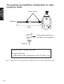
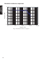
Random incidence response
Description
for IEC
2
Response (dB)
0
-2
-4
-6
-8
-10
10
100
1 000
Frequency (Hz)
10 000
Fig. 8 Random incidence response
46
100 000
No. 53732
09-07