1
United States Patent [191
[11]
4,448,058
Jaffe et al.
[45]
May 15, 1984
[54] RESPIRATORY GAS ANALYSIS
INSTRUMENT HAVING IMPROVED
VOLUME CALIBRATION METHOD AND
APPARATUS
[75] Inventors: Michael B. Jaffe; Charles R. Luper,
both of Anaheim; Eric Mabry,
Westminster; Howard J. Reid, Brea,
all of Calif.
[73] Assignee: Sensormedics Corporation, Anaheim,
Calif.
FOREIGN PATENT DOCUMENTS
2950746
6/1981
Fed. Rep. of Germany ...... .. 422/84
Primary Examiner—Stephen A. Kreitman
Attorney, Agent, or Firm-Lyon & Lyon
[57]
ABSTRACT
An improved gas volume calibration method and appa
ratus for use in respiratory gas analyzers. A control unit
monitors the ?ow of calibration gas through the analy
zer by monitoring the electrical signals produced by a
gas turbine and a breath switch. During calibration, a
[21] Appl. No.: 394,608
Jul. 2, 1982
[22] Filed:
known volume of calibration gas is repeatedly delivered
to the analyzer from a calibration syringe at each of a
number of different flow rates. On the basis of the infor
[51]
Int. Cl.3 ........................................... .. G01N 31/00
[52]
US. Cl. ....................................... .. 73/23; 73/1 G;
128/719; 364/571
mation received from the turbine and the breath switch,
the control unit generates and stores a’piecewise linear
[58]
Field of Search ................. .. 73/23, 1 G; 128/719;
approximation of ‘the nonlinear characteristic of the
422/ 84; 436/900; 364/571, 497
turbine. This stored turbine characteristic is then made
available during subsequent measurements to eliminate
[56]
References Cited
U.S. PATENT DOCUMENTS
those volume errors which are associated with varia
tions in the rate at which the sample gas is delivered,
73/1 G
422/84
4,316,380 2/1982 Heim et a1. ........................... .. 73/23
3,948,604
4/ 1976
4,178,919 l2/1979
Hoppesch .......... ..
thereby affording measurements of improved accuracy.
Hall ............. ..
50 Claims, 8 Drawing Figures
P ULSES/ UTER
/ //
/ V
525
yfmexa?e
--
////Aia
/’
/
l
2000
1
.
l
‘3000
PULSES
SECOND.
I+
Pa one’ Pa MEAS
Pa CALC
US. Patent
May 15, 1984
Sheet 3 of7
FIG. 4
4,448,058
US. Patent
May 15, 1984
Sheet 5 of 7
STA/2T VOLUME
CALIBRATION
6(a)
ZOO
sz'r N=l
AND THE
®———:
I FETCH N
|~/~202
OUTPUT Magma‘
SET SYRmGE TO
./" 204
SETT\NG N M40
PusH ENT EW
@:§3~214 (we
OUTPUT MESSAGE‘.
aEAoY Fon STQOKE c5 0; T
AT 5ETT\NG N
mpu-r sTrioKs
DURA'HON AND
PULSE COUNT
\L
Cp
4,448,058
US. Patent
May 15, 1984
Sheet 6 of 7
T
FETCH
MlN.
PULSE COUNT CM
~222
224-
'
No
(\228
ouTPuT MESSAGE:
\NCQMPLETE STROKE
AT sen-me N
Yes
COMPUTE @- STQQE
PULSES pen sac
r226
Pm
V
‘FETCH MAX
6- MlN
P/SEC
fz-go
PM max 5 PNMIN
OUTPUT
msssaea:
' REDOQTROKE
FASTER
’( )
r242
OUTPUT
‘
msssAcaa :
Reno s'rnoka
SLOWER
\NCREMENT
STROKE
C COUNT
L
f256
8
4,448,058
U.S. Patent
May 15, 1984
4,448,058
Sheet 7 of 7
6 (c)
244
CLEAR COU NTER A
262
|
co MPUTE COEF'F. 0F
VARIATlON
C
FETCH CVMAX.
Z56
r246
OUTPUT
DELETE Two
s‘mokas
Fun-m EST
FROM MEAN
254
NO
260
l N CREMENT
COU NTER
A
YES
("2.58
INcriEMENT
COLJ NTER
D
cOMPUTE
F264
f25o
CQRRECTION
OUTPUT
FACTOR FM
MESSAGE‘.
SEEUSER'S
MANUAL
270
C272
NO
INCREMENT
N
YES
coMPuTE
H VALUES
'
GENERATE
AND 5mm;
EQUATIONS
FOR CURVE
Ca
EXIT
W276
NO
1
4,448,058
2
through the instrument are more complex than they
RESPIRATORY GAS ANALYSIS INSTRUMENT
would be in the absence of a bias gas ?ow.
HAVING HHPROYED VOLUME CALIBRATION
SUMMARY OF THE INVENTION
In accordance with the present invention, there is
provided an improved method and apparatus for cali
brating a respiratory gas measuring instrument which is
not subject to the above-described problems and which
affords high gas volume calibration accuracy without
requiring the use of bias gas ?ows.
The present invention provides a method and appara
METHOD AND APPARATUS
BACKGROUND OF THE INVENTION
In calibrating respiratory gas analysis instruments, it
has long been the practice to supply the instrument with
a pulsatile flow of calibration gas (usually air) from a
device known as a calibration syringe. This syringe
typically includes a piston and cylinder arrangement
which pumps gas into the instrument, through a check
valve, as the operator moves the piston between ?rst
and second positions. Because the cylinder has a volume
comparable to the volume of gas that is exhaled during
a typical human breath, and because the ejection stroke
of the piston has approximately the same duration as an
exhaled breath, the calibration syringe allows the instru
tus by which data received from a gas turbine and a
breath switch during calibration are used to produce a
nonlinear characteristic curve for the turbine. The re
sulting characteristic curve is made available for use
during the taking of measurements to provide corrected
gas volume data that takes into account the duration
and rate of ?ow of each breath. Because measurements
of the concentration of the gaseous components of
ment to be calibrated under conditions that simulate 20 breath are strongly affected by the volume thereof‘, the
gas concentration readings which are based on this
those which exist when the instrument is later used with
corrected volume data have an accuracy better than
a test subject.
that available prior to the present invention.
The use of known volume calibration syringes and
In accordance with another feature of the present
procedures has been found to result in sizable errors in
the volume of gas delivered during calibration. One 25 invention, the instrument is arranged to prompt the
operator who calibrates it, and thereby lead him
through the volume calibration process in a way that
the fact that the inertia of the gas ?owing through the
assures that the latter is properly performed. In the
check valve has a tendency to open the check valve
event that any of the steps of the volume calibration
when the piston reaches the end of its ‘stroke. Such
siphoning affects the accuracy of the calibration process 30 process are improperly performed, the instrument will
cause of this error, known as “siphoning”, results from
by causing the actual volume of gas supplied to the
instrument to exceed the volume of the calibration sy
ringe.
Another error that is associated with the use of manu
ally operated calibration syringes results from the fact
that, due to operator inattention, the piston may not be
moved between exactly the same beginning and end
positions during each ejection stroke. An operator may,
for example, not withdraw the piston to its true outer
most position, or may not push the piston to its true
innermost position. Any such deviations from the de
reject the resulting faulty data and inform the operator
of what he must do to provide acceptable data. Once an
acceptable set of data is available, the instrument auto
matically produces a piecewise linear approximation of
35 the non-linear characteristic of the turbine and stores
the same for use during subsequent measurements.
In spite of the sophisticated nature of the calibration
system of the invention, the calibration process itself is,
from the operator’s standpoint, quite simply and conve
niently performed. As a result, it is practical to volume
calibrate the instrument daily or even before each series
of measurements. Such frequent calibrations are desir
able because the characteristics of a turbine can change
delivered by the syringe during calibration and, there
with wear and with the accumulation of dirt on the
fore, the accuracy of all measurements that are based on 45 blades or bearings. Thus, the volume calibration
that calibration.
method and apparatus of the invention assures that the
Another even larger error that isassociated with the
instrument always has available to it volume data which
use of manually operated calibration syringes is the
reflects the current condition of the turbine.
error that results from the nonlinearity of the response
Generally speaking, the calibration system of the
sired inner and outer positions affect the volume of gas
of the gas turbine. This nonlinearity can cause the num
ber of output pulses that are produced by the turbine
during the ?ow of a known volume of calibration gas to
vary substantially, depending upon the rate at which the
gas is delivered. The dif?culty is that most operators
present invention contemplates the storage of a piece
wise linear approximation of the nonlinear characteris
tic of a typical gas turbine of the type used in the instru
ment. Each of the linear segments of this characteristic
represents a particular range of turbine pulses per unit
have dif?culty in operating the syringe in a consistent 55 volume of calibration gas as a function of the rate at
which that gas is delivered. On the basis of the turbine
produced during an ejection stroke of the syringe will
output‘data that is gathered as the operator manually
vary randomly from stroke to stroke. In the past this
operates the syringe, the instrument generates a correc
nonlinearity has been dealt with by introducing a flow
tion factor for each piecewise-linear segment. When all
of a “bias” gas which causes the rate of gas flow
of these correction factors are available, the instrument
then generates a corrected piecewise linear approxima
through the turbine to remain in a range of values
tion of the characteristic curve of the actual turbine.
within which its response is relatively ?at. This ap
The latter characteristic is then stored for use during the
proach, however, only partially solves the problem. It
taking of measurements. As a result of the availability of
does not actually eliminate variations in the turbine
output with variations in the rate of ?ow therethrough. 65 this nonlinear approximation of the actual turbine char
acteristic, the instrument is able to provide accurate
In any case, the use of bias gas flows is expensive since
concentration readings, in spite of changes in the rate at
it requires the establishment of an additional accurately
which the test subject breaths.
controlled gas ?ow, and since the gas ?ow paths
manner. As a result the number of turbine output pulses
3
4,448,058
DESCRIPTION OF THE DRAWINGS
Further objects and advantages of the present inven
tion will be apparent from the following description and
drawings in which:
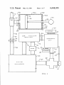
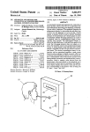
FIG. 1 is a block diagram of a respiratory gas analysis
instrument, shown with the connections which exist
during volume calibration, including a known type of
calibration syringe,
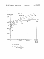
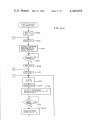
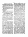
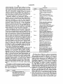
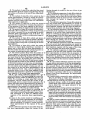
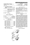
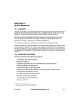
FIG. 2 is a graph showing a piecewise linear approxi
mation of the operating characteristic of the gas turbine
of FIG. 1,
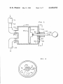
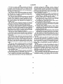
FIG. 3 is a cross-sectional view of an improved vol
ume calibration syringe constructed in accordance with
the present invention,
FIG. 4 is a cross-sectional view taken along the line
4—4 of FIG. 3,
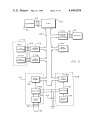
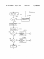
FIG. 5 is a block diagram of the electronic control
unit of FIG. 1, and
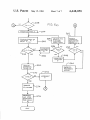
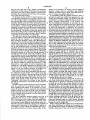
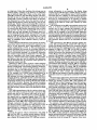
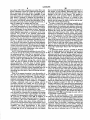
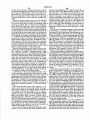
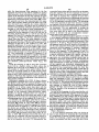
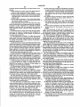
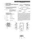
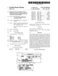
FIGS. 60, b and c together comprise a ?ow chart that
depicts the sequence of operations that are performed
by the control unit of FIG. 5 during volume calibration.
4
blades, not shown, which are arranged to rotate as gas
?ows thereover. These blades are ordinarily arranged
to interrupt the beams of light which a plurality of
LED’s direct against a plurality of respective photo
transistors to produce a multi-phase set of output pulses
on conductors 42. Thus, turbine 38 supplies to control
unit 20, over conductors 42, a train of pulses the number
and frequency of which varies in accordance with the
volume and rate of flow of gas ?owing therethrough.
Combination check valve-breath switch 40, which
may be of a known type, preferably includes a check
valve 41 which is gently biased in its closed position to
assure that gas enters mixing chamber 26 only through
inlet line 28. Device 40 also includes a breath switch
15 (not shown) which assumes a ?rst state when valve 41 is
open, and a second state when valve 41 is closed. Be
cause of the cyclic nature of breath, the openings and
closings of the breath switch mark the beginnings and
endings of breaths. The state of the breath switch is
monitored by control unit 20, through conductors 44, to
enable it to interpret the concentration readings from
gas analysis section 12. In particular, by counting the
number of pulses received from the gas turbine during
DESCRIPTION OF THE PREFERRED
the time that the breath switch is open, the volume of
EMBODIMENT
25 each breath is determined so that it may be used in
Referring to FIG. 1, there is shown a block diagram
interpreting the concentration readings provided by gas
of a respiratory gas analysis instrument 10 which is
analysis section 12.
shown with the connections which exist during volume
Because the response of a gas turbine is known to be
calibration. Instrument 10 includes a‘gas analysis section
nonlinear, it has been the practice, prior to the present
12 which may comprise one or more gas analyzers such 30 invention, to maintain a ?ow of bias gas through a tur
as, for example, nondispersive infrared gas analyzers.
bine and thereby maintain the latter within a relatively
For measurements on human breath these analyzers will
typically include one analyzer that is sensitive to the
concentration of oxygen and another that is sensitive to
sion of an accurately regulated source of such bias gas
is, however, relatively costly. Moreover, because of the
the concentration of carbon dioxide. The sample gas
nonlinearities associated with the mixing of the sample
that is measured by these analyzers is circulated
through analysis section 12 by a pump 14 which drives
the sample gas through the path including an inlet line
bine characteristic, such an approach is relatively inac
?at portion of its operating characteristic. The provi
and bias. gases, as well as the residual slope of the tur
curate. In accordance with one feature of the present
16 and an outlet line 18.
invention, the use of a bias gas flow is eliminated and the
The instrument of FIG. 1 also includes an electronic 40 nonlinear response of turbine 38 is dealt with by cali
control unit 20 which is connected to analysis section 12
brating instrument 10 at a variety of different gas ?ow
rates and thereby providing it with the ability to derive
keyboard 23 through a set of electrical conductors 24,
accurate volume data from turbine 38 in spite of ?uctua
and to an operator-readable display 25 through a set of
tions in the rate of gas ?ow therethrough. In this man
electrical conductors 26. Control unit 20 may include 45 ner the instrument as a whole is made able to provide
electronic circuitry of either the hard-wired type or the
measurements of improved accuracy over a wide range
microcomputer-controlled type, although the latter are
of sample flow rates.
preferred because of their greater cost effectiveness.
In particular, in calibrating instrument 10 in accor
The gas to be measured is supplied to analysis section
dance with the present invention, control unit 20 takes
12 from a mixing chamber 26 which is provided with an 50 a previously stored piecewise linear approximation of
inlet line 28 and an outlet line 29. In order to facilitate
the nonlinear characteristic of a representative turbine
the connection of inlet line 28 to either a source of
of the type being used, and combines the same with
through a plurality of electrical conductors 22, to a >
sample gas or a source of calibration gas, inlet line 28
turbine data that is produced as an operator directs an
preferably terminates at one end of a connector 30 that
accurately known volume of gas through the turbine at
is mounted on an interface panel 32. The other end of 55 a plurality of different ?ow rates. This gas is supplied
connector 30 is thereby made available for coupling to
through the use of an improved volume calibration
the desired sample or calibration gas source. In FIG. 1
connector 30 is connected to a line 34, which leads to a
source of calibration gas, namely: volume calibration
syringe that reduces operator-related volume errors.
syringe 50.
In order that control unit 20 may monitor the volume
and rate of ?ow of the gas ?owing out of mixing cham
ber 26, there is provided a gas turbine 38, which is
Based on the data received, control unit 20 produces
and stores a corrected piecewise linear approximation
that reflects the nonlinear response of the actual gas
turbine then being used. Illustrative ones of these piece
wise linear approximations of representative and indi
vidual turbine characteristics are shown as “curves” C1
connected to control unit 20 through a set of electrical
and C2, respectively, of FIG. 2, which will be described
conductors 42, and a combination check valve and 65 in detail later. The calibration method and apparatus by
breath switch 40, which is connected to control unit 20
which this desirable result is accomplished enables the
through a set of electrical conductors 44. Gas turbine 38
instrument to operate with high accuracy at a variety of
is preferably of a known type that includes turbine
sample gas ?ow rates not only after its initial calibra
5
4,448,058
tion, but also after each of any number of subsequent
6
are preserved in spite of those changes in turbine char
absence of a procedure for dealing with the different
apparent volumes that are associated with different
numbers of turbine output values, such differences re
acteristics that are associated with wear, the accumula
sult in volume uncertainties and errors.
tion of dirt and other factors.
In the upper portion of FIG. 1, there is shown a vol
In accordance with the present invention, there is
provided an improved method and apparatus for cali
ume calibration syringe 50 of a type that is known in the
brating the instrument of FIG. 1 at gas flow rates that
correspond to a number of different regions of the non
calibrations. In this manner the bene?ts of the invention
art. This syringe includes a housing 52 having a cylin
drical section 520, a ?rst end plate 52b, and a second end
plate 520. Slidably mounted within housing 52 is a pis
linear operating characteristic of its turbine, and
thereby enabling the instrument to determine the vol
ton 54 which is sealed to the inner surface of cylindrical
section 52a by a suitable O-ring 56. Piston 54 is driven
manually by means of a shaft 58, having a knob-shaped
handle 59, which is slidably mounted on end plate 52b
by a bushing 60. The partial vacuum that tends to arise 15
rates. In addition, for each of the plurality of ?ow rates
at which the instrument is calibrated, the invention
imposes criteria for the acceptance or nonacceptance of
the turbine data that is produced by the operation of the
umes of gas that are later delivered at any of those ?ow
behind the trailing surface of piston 54 during the ejec
syringe, thereby assuring that only ejection strokes that
tion stroke thereof is relieved by the in-?ow of ambient
air through an aperture 62 in end plate 52b.
The gas that is ejected from syringe 50 by the for
meet predetermined minimum standards are used in the
calibration process. Finally, the present invention con
templates improvements to the calibration syringe itself,
ward movement of piston 54 flows through an outlet 20 which improvements eliminate the above-mentioned
nipple 64 which is coupled to a T-connector 66. The
siphoning problem and facilitate the establishment of a
latter connector includes a check valve 68 which per
number of different calibration gas delivery rates. To
mits gas to ?ow inwardly through atmospheric inlet line
gether these improvements greatly improve the accu
70, but not in the reverse direction. During the intake
racy of the calibration of the instrument and thereby
stroke of piston 54, check valve 68 opens to admit ambi 25 improve the accuracy of all of the subsequent measure
ent air (the calibration gas) to syringe 50. Under this
ment that are based thereon.
'
To the end that the above-mentioned siphoning prob
condition, check valve 41 is closed, preventing syringe
50 from drawing gas from mixing chamber 26. During
lem may be eliminated, the preferred embodiment of the
the ejection stroke of syringe 50, check valve 68 closes,
present invention includes an improved gas volume
forcing the ejected air to flow into mixing chamber 26 30 calibration syringe 50' shown in FIGS. 3 and 4. The
through lines 34 and 28. Under this condition, check
syringe of FIG. 3 is in some respects similar to that of
valve 41 opens to vent to the atmosphere the gas that is
FIG. 1, like functioning parts being similarly numbered,
displaced from mixing chamber 26. Thus, as piston 54 is
but differs therefrom in several important respects. The
repeatedly moved between its ?rst or outermost posi
?rst of these is that, in the syringe of FIG. 3, end plate
tion and its second or innermost position, mixing cham 35 526 is modi?ed to provide separate inlet and output
ber 26 is provided with a pulsatile ?ow of calibration
nipples 64a and 64b, respectively. Associated with this
gas which is similar in quantity and character to that
produced by a test subject. It will be understood that
ambient air is a desirable calibration gas because of the
difference is the elimination of T-connector 66 of FIG.
1 and the connection of a check valve 68 in series with
line 70. Finally a ?at rubber covering 54a is attached to
fact that it is the change which the cardiopulmonary 40 the leading edge of piston 54. Together these modi?ca
system of the test subject produces on ambient air
tions eliminate the above-described siphoning problem.
which is of interest to the user of instrument 10.
This is because, when piston 54 reaches the end of its
One source of error that is associated with the use of
stroke, rubber covering 54a makes contact with the
the calibration syringe of FIG. 1 is a volume error that
inner surface of second end plate 52c, thereby suddenly
is caused by the inertia of the gas that ?ows in line 34 45 cutting off the flow of gas in lines 70 and 34. As a result
during an ejection stroke. This gas ?ow tends to open
of this positive shut-off, no additional gas can enter
check valve 68 after piston 54 reaches the end of its
chamber 26 after the end of a stroke.
A second improvement in syringe 50' of FIG. 3 re
stroke. This opening of the check valve is known as
sults from the provision therein of a control plate 80
“siphoning” and causes the volume of gas ?owing
which allows an operator to selectably control the rate
through the instrument to exceed the actual volume of
the syringe.
at which air can ?ow into syringe through end plate
aperture 62. As is most clearly seen in FIG. 4, control
Another operator-related source of error is associated
plate 80 includes a sector-shaped section 800, which is
with the occurrence of incomplete strokes, such as
provided with one or more ?ow-limiting holes such as
those resulting from failure of an operator to move
piston 54 between its true outermost and innermost 55 82, and a circular section 80b which is centered on shaft
positions during each ejection stroke. Such incomplete
58. In the preferred embodiment, control plate 80 is
held against the outer surface of end plate 52b by being
strokes naturally cause the volume of gas that is caused
sandwiched between that end plate and a control mem
to ?ow through the instrument to be less than the full
ber 84 which is rotatably fastened to plate 52b by a
volume of the syringe.
The most important operator-related error that is 60 suitable retaining washer 86. A pin 88 which ?ts into
control plate 80 and control member 84 assures that
associated with the use of the calibration syringe of
these two elements rotate as a unit, thereby allowing
FIG. 1, however, is the volume error that results from
plate 80 to be conveniently positioned by grasping and
moves piston 54 during a series of ejection strokes. This
turning the end of member 84.
error occurs because different stroke speeds cause tur
When control plate 80 is rotated to its counterclock
bine 38 to operate at different regions of its non-linear 65
wise limit, which may be de?ned by the position of a
characteristic. Operation at these different regions in
turn causes a known volume of calibration gas to pro
stop pin 90, aperture 62 is not blocked by plate 80 and
duce different numbers of turbine output pulses. In the
therefore allows gas to ?ow into the rear of syringe 50’
7
4,448,058
at a high rate. Under this condition, the syringe may be
stroked rapidly, resulting in the delivery of calibration
gas at relatively high rates. When, on the other hand,
plate 80 is rotated so that hole 82 is aligned with aper
8
nicate information to an operator, the display being
coupled to bus 102 through a suitable display interface
network 106 of a conventional type. ‘It will be under
stood that the term “display” is used herein in its broad
ture 62, the rate at which gas can flow into the rear of 5 sense to refer to any device by means of which informa
syringe 50’ is greatly reduced. The effect of this ?ow
tion may be communicated to an operator in human
readable form and includes, for example, alphanumeric
rate reduction is to slow down the ejection stroke of
syringe 50 and thereby reduce the delivery rate of cali
bration gas. Finally, when control plate 80 is rotated to
its clockwise limit, which may be de?ned by the posi
tion of stop pin 92, aperture 62 is substantially blocked
Also connected to bus 102 is gas analysis section 12 of
FIG. 1. As shown in FIG. 5, analysis section 12 may
by control plate 80, thereby limiting the rate at which
include one or more separate gas analyzers, such as
gas can flow into the rear of syringe 50’ to the rate at
which gas can leak through the clearance space be
oxygen analyzer 108 and carbon dioxide analyzer 110,
which may be coupled to bus 102 through respective
displays of the LED or LCD types, cathode ray tubes
and printers.
tween plates 80 and 52b. Under this condition, strokes
interface boards 112 and 114. Because these gas analy
can be completed only slowly, resulting in a low gas
zers and interface boards operate in a manner known to
. delivery rate. It will therefore by seen that, for a given
those skilled in the art to supply gas concentration infor
mation to bus 102 on command, the internal structure
amount of stroke force by an operator, the syringe of
FIG. 3 establishes three different delivery rates for
calibration gas.
and operation thereof will not be described in detail
20 herein.
Also connected to bus 102 are gas ?ow sensing net
In the preferred embodiment of the present invention,
works 118 and.128 through which CPU 100 receives
these three delivery rates correspond to segments A, B
turbine and breath switch data over conductors 42 and
and C of the piecewise linear approximation of the
turbine characteristic of FIG. 2. This correspondence
44. Of these gas ?ow sensing networks, network 118 is
greatly facilitates the process of providing calibration 25 adapted to supply to CPU 100, via bus 102, a number
indicative of the total number of pulses produced by
data to the instrument for each of linear segments A, B
turbine 38 between the opening and closing of breath
and C and thereby enabling it to accurately determine
switch 40. To the end that this may be accomplished,
the volumes of gas which are delivered to it at the rates
that are associated with those linear segments. The
manner in which turbine data produced at these differ
network 118 includes a suitable input circuit 120 for
logically OR-ing the multi-phase signals produced by
ent delivery rates are used to calibrate the instrument
the various LED phototransistor pairs within turbine 38
will be described later in connection with operation of
into a single pulse train, a counter 122 for counting the
number of pulses produced by input circuit 120 and a
~
conventional bus interface network 124 for supplying
Referring to FIG. 5, there is shown a block diagram
of the contents of control unit 20, those elements which 35 the contents of counter 122 to CPU 100 upon command.
The counting activity of counter 122 is coordinated
appear in both FIGS. 1 and 5 being similarly numbered.
with the state of breath switch 40 by applying the out
As shown in FIG. 5, control unit 20 includes a central
electronic control unit 20.
processor unit or CPU 100 which may be of any of a
put of breath switch 40 thereto as an enable signal, via
conductors 44. After counter 122 communicates to
number of different commercially available types such
as, for example, an LS-480O board manufactured by 40 CPU 100 the total number of turbine output pulses, it is
preferably reset by an appropriate command from CPU
Beckman Instruments, Inc. Generally speaking, CPU
100.
100 includes the usual arithmetic-logic unit (ALU), a
Breath duration information from breath switch 40 is
program memory, preferably stored in read-only mem
provided to CPU 100 by gas flow sensing network 128
ory (ROM), a plurality of working registers, preferably
comprising random access memory (RAM) and suitable 45 which may include a counter 130, a bus interface net
work 132 and a ?xed frequency clock 134 having a
clock drive circuitry. Because the present invention
frequency of, for example, 40 KHz. Like counter 122,
may be understood without reference to the internal
counter 130 is enabled by the signal on conductors 44
operation and circuitry of CPU 100, the internal opera
when breath switch 40 is open. During the time that it
tion and circuitry thereof will not be described in detail
herein.
is enabled, counter 130 counts the pulses received from
CPU 100 communicates with the various circuit net
works with which it operates through a system bus 102
which may also be of a known type, such as the well
known “multi-bus”. This bus carries a number-of differ
clock 134 and stores the same until CPU 100 requests
the same through bus interface network 132. After this
information has been supplied to CPU 100, counter 130
is preferably reset by an appropriate command from
ent signals such as command signals from CPU 100, 55 CPU 100 in preparation for the next operation of breath
switch 40. Because counter 130 counts pulses having a
status signals to CPU 100, and data signals both to and
?xed frequency, the number stored in counter 130 dur
from CPU 100, all such signals being codedin multi-bit
ing a breath is indicative of the duration of that breath.
digital form. CPU 100 isalso connected to keyboard 23
In summary, ?ow sensing network 118 supplies to
through conductors 24 and a CPU input/output port
(not shown) which is available for that purpose on the 60 CPU 100 the total number of output pulses produced by
turbine 38 during each operation of breath switch 40.
abovementioned LS-4800 board. Alternatively, key
During calibration this number is equal to the number of
board 23 may be connected to CPU 100, through bus
pulses produced during an ejection stroke of syringe
102, provided that a suitable bus interface network is
50’. In addition, flow sensing network 128 supplies to
present.
Among the devices which communicate with CPU 65 CPU 100 a number indicative of the length of the time
period during which breath switch 40 was open. During
100 over bus 102 is a random access memory (RAM)
calibration this number is indicative of the duration of
104 which serves as bulk read-write storage for unit 20,
an ejection stroke of syringe 50'. Together, these num
and a display 25 through which CPU 100 may commu
9
4,448,058
bers allow CPU 100 to generate an actual flow rate
signal, preferably in terms of a pulses-per-second value,
that is associated with each stroke of syringe 50'. In
accordance with the invention the availability of the
latter information for a plurality of calibration gas ?ow
rates makes it possible to calibrate the instrument of
FIG. 1 over substantially the entire operating range of
the turbine, and thereby enables the instrument to later
determine the actual volume of sample gas delivered, in
10
that are received during subsequent measurements on a
test subject. In this manner, instrument 10 is able to
accurately determine the volume of a breath in spite of
changes in the rate of How thereof. The manner in
which curve C2 is produced will be described pres
ently. Before doing so, however, it is helpful to ?rst
discuss the form in which a curve such as curve C1 is
stored, and the manner in which it can be used in mak
ing breath volume determinations.
In order to make the most efficient possible use of
10
spite of changes in the sample gas ?ow rate.
memory, curve C1 is stored in the ROM of CPU 100 by
Referring to FIG. 2, “curve” C1 represents a piece
storing therein the maximum and minimum pulses-per
wise linear approximation of the nonlinear characteris
tic of a typical turbine of the class of turbines to which
turbine 38 belongs. As used herein, the term "piecewise
linear approximation” refers to a set of linear segments
which together approximate a continuous curve. Line
segments A-E of FIG. 2, for example, approximate
respective curvilinear sections of the continuous curve
(not shown) that characterizes the response of a typical
turbine of the class of turbines to which turbine 38 be
longs. The number of linear segments included in curve
C1 may, in general, have any value. For practical rea
second values that are associated with each of line seg
ments A-E of FIG. 2 (such as PBMAX and PBMIN for
segment (B), along with the equations of the line seg
ments that apply between those values. These latter
equations are preferably stored by storing the parame
ters of these equations as expressed in slope-intercept
form, i.e., in the form y=m.x+b, where y is the vertical
axis variable, x is the horizontal axis variable, m is the
slope of the line and b is the y axis intercept. This form
of storage allows each line segment to be uniquely spec
i?ed in terms of only four stored values, namely PMAX,
sons, however, the number of piecewise linear segments
PMIN, m and b. Naturally, the equations for these line
is preferably as small as is possible in view of the desired
volume correction accuracy. It will therefore be under 25 segments may also be stored in other well-known forms,
stood that the ?ve linear segments A-E shown in FIG.
2 represent a reasonable compromise value which af
such as the “point-slope” form or the “two-point” form,
if desired.
fords both accuracy and ease of use.
v As pulses-per-second data for a breath is derived
from the output signals of turbine 38 and breath switch
In FIG. 2 the horizontal ‘axis indicates the rate of ?ow
of a breath through the turbine, and is scaled in terms of 30 40, it is compared with the maximum and minimum
pulses-per-second values of each line segment until the
the pulses-per-second‘ value that is associated with a
segment alongwhich it lies is identi?ed. The pulses-per
particular breath. The vertical axis indicates the total
number of pulses produced by the turbine per unit vol~
ume of breath at the indicated ?ow rate. Because the
volume of the calibration syringe has a known ?xed
value, the unit of volume of breathlwill also be ?xed
second value may then be substituted into the equation
for the line segment, which is then solved to provide the
pulses-per-liter value which corresponds to the mea
during calibration. From the shape'of typical turbine
sured pulses-per-second value. Once the pulses-per-liter
value is available, volume data for the breath may be
characteristic curve C1, it is apparent that the number
provided in one of two forms. On the one hand, the
pulses-per-liter value may be divided into the total num
of pulses produced per ejection stroke of syringe 50’ can
have a number of different values, depending upon the 40 ber of pulses to yield a volume value in liters. Alterna
tively, the pulse-per-liter value maybe divided into the
?ow rate that is associated with that ejection stroke, i.e.,
pulses-per-second value to produce volume data in the
depending upon the speed of piston 54 during that ejec
form of a volume rate of ?ow in liters per second. Note
tion stroke.
that volume rate of ?ow in liters-per-second need only
Prior to the present invention it was the practice to
deal with the nonlinear response of a turbine by direct 45 be multiplied bythe duration of a breath to yield the
volume of a breath in liters. Since one or both of these
ing a ?ow of bias gas therethrough. This bias gas ?ow
determinations may be made for any point on curve C1,
caused all turbine output data to be associated with a
it will be seen that the storage and use of curve C1
relatively horizontal region of curve C1, such as the
allows the volume data for a breath to be determined in
region corresponding to linear segment A. In addition
to being a relatively costly way of dealing with the 50 spite of changes in regard to the rate at which that
breath is delivered.,This in turn allows the instrument as
non-linear response of a turbine, the use of a bias gas
a, whole to correctly interpret the output data from the
?ow introduced new inaccuracies as a result of the fact
gas analyzers of gas analysis section 12. Because the
that the chosen region was only approximately horizon
manner in which each of the above-described compari
tal and the fact that the characteristics of a turbine
55 sons and algebraic manipulations may be performed is
change with time and the accumulation of dirt. .
well known to programmers, the speci?c steps that are
In accordance with one feature of the present inven
followed by CPU 100 in performing the same will not
tion, the need for a bias gas ?ow is eliminated by storing
be described in detail herein.
a complete piecewise linear approximation C1 of the
_ While the above-described volume determination
response of a representative turbine within control 'unit
20, preferably in a ROM in CPU 100. In addition, in 60 takes into account the nonlinearity of a typical turbine,
it does not take into account the differences between a
accordance with another important feature of the pres
particular turbine and a typical turbine of the same type.
ent invention, this stored characteristic is combined
In accordance with an important feature of the present
with actual turbine data taken during calibration to
invention, there is provided a calibration method and
produce a second piecewise linear approximation C2 of
the response of the actual turbine in its then current 65 apparatus whereby stored curve C1 of FIG. 2 and the
pulses-per-second data that is received for a plurality of
condition. The latter approximation is also stored
within control unit 20, preferably (but not necessarily)
in RAM 104, for use in interpreting ?ow rate signals
gas ?ow rates during calibration are combined to pro
duce and store a corrected curve C2 that reflects the
11
4,448,058
12
actual properties of the particular turbine in its then
-continued
current operating condition. This corrected curve may
then be used in the above-described manner to provide
Symbol
gas volume data which the instrument can use to pro
B _
B is a variable that represents the
number of times an operator has at
tempted to produce an acceptable set
of strokes at setting N of the syr
C; —
CS is a variable representing the
vide gas concentration readings having an accuracy
which far surpasses that available from respiratory in
struments that were available prior to the present inven
Meaning
‘
inge.
tion. The manner in which corrected curve C2 is pro
number of acceptable syringe strokes
duced during calibration will now be described.
which have been made by the operator
at setting N.
Generally speaking, the information necessary to
generate curve C2 is produced during calibration by
using syringe 50’ to produce turbine output data at ?ow
T is a constant that indicates the
rates that correspond to at least the most frequently
used ones of line segments A-E of curve C1 of FIG. 2.
strokes which are necessary to fix the
position of one line segment of curve
total number of acceptable syringe
C2.
In the preferred embodiment, this turbine output data is
produced without the need for a costly mechanical
device for driving piston 54. This is accomplished by
communicating to an operator, through display 25, the
information necessary for the operator to manually
Cm
stroke syringe 50 at the speeds which will result in the
desired pulses-per-second values from turbine 38.
More particularly, after control unit 20 has been
placed in its calibration mode, it outputs a message to
the operator requesting him to stroke syringe 50' so that
C‘, is the total number of pulses pro
duced by turbine 38 during an ejec
tion stroke of the syringe.
Cm is a constant representing the
minimum number of pulses which must be
produced by turbine 38 during a stroke
in order for the stroke to be consid
ered an acceptable one.
PN
_P1vis the pulses-per-second value
resulting from an ejection stroke of
the syringe at setting N.
Pym“ is a constant indicating the
maximum acceptable pulses-per-second
it may receive turbine output data for a ?rst line seg
ment such as segment A’ of curve C2. If the stroke is too
fast or too slow, control unit 20 will reject the resulting
data and request the operator to repeat the stroke at a
faster or slower rate. This process is repeated until suffi
PNmin —
value at setting N; this value corres
ponds to the upper endpoint of one of
the line segments of curves Cl and C2.
PNm-n is a constant that indicates the
minimum acceptable pulses-per-second
stroke the syringe so that it may receive turbine output
data for another line segment such as segment B’ of
value at setting N; this value corres
ponds to the lower end of one of the
line segments of curves Cl and C2.
A is a variable representing the num
ber of times that a loop has been tra
versed.
curve C2. Again the control unit accepts only data 35
resulting from strokes of the proper speed and informs
coef?cient of variation of a set of
strokes at a particular setting, that
cient information for the ?rst linear segment has been
received. Control unit 20 then requests the operator,
through display 25, to change the syringe setting and
the operator whether unacceptable strokes are too fast
or too slow. This process is then repeated for the de
sired number of additional line segments.
Once the operator has entered sufficient turbine data
for each of the desired line segments, this data is used to
generate a set of correction factors which, in effect,
determine new intercepts for the equations of the line
segments of curve C1. These new intercepts, together
with the stored slopes of the line segments of curve Cl,
de?ne a corrected piecewise linear approximation C2
which re?ects the response of the actual turbine being
used. The latter is then stored for use by control unit 20
in interpreting the volume of gas delivered during all
subsequent measurements, i.e., until the next volume
calibration. The result is an instrument which is accu
rately volume calibrated not only in view of the nonlin
earity of the gas turbines generally, also in view of the
individual characteristics of the actual turbine being
C, is a variable representing the
is, the standard deviation of the
pulses-per-second values of the
strokes divided by the mean pulses
per—second value thereof.
FcN —
FtN is a correction factor which spe
ci?es the'position of a line segment
of curve C2 with respect to the posi
tion of the corresponding segment of
curve Cl; a correction factor will
exist for each setting of N.
The How chart of FIGS. 6a-c will now be described.
Upon entering the volume calibration sequence and
encountering block 200, CPU 100 sets N=l to select a
first line segment such as A’ (i.e. a ?rst gas flow rate) for
which to receive turbine data. CPU 100 also sets T=8,
indicating that 8 acceptable strokes are necessary to fur
the position of segment A’. The set value of N is used in
blocks 202 and 204 to output to the operator, on display
55 25, the message “set syringe to setting 1 and push en
used.
ter”. CPU 100 then enters a wait loop, indicated by
The manner in which the present invention operates
to accomplish the above-described results is most easily
understood in connection with the flow chart of FIGS.
60-0. The meanings of the various symbols used in this
?ow chart are as follows:
Symbol
Meaning
N—
N is a variable that identi?es the
linear segment of curve C1 or C2 for
which turbine data is being received,
and the syringe setting (position of
control plate 80) that is associated
with that segment.
block 206, which is exited when the operator makes the
requested syringe setting and pushes the enter button on
keyboard 23. After CPU 100 exits this wait loop, it sets
variable B=0, as indicated by block 208, and sets vari
able C_,: l, as indicated by block 210. Upon encounter
ing block 212, CPU 100 clears flow sensing networks
118 and 128 of FIG. 5 to prepare the same for the re
ceipt of data from the turbine 38 and breath switch 40.
65 After these networks are cleared, CPU 100 fetches the
current values for Cs and T and outputs to the operator
the message “ready for stroke 1 of 8 at setting 1”, as
indicated by blocks 214 and 216. This informs the opera
13
4,448,058
14
.
tor that the instrument is ready for the ?rst stroke of
syringe 50’and that eight acceptable strokes are neces
sary to gather suf?cient data to ?x the new position of
line segment A’. The instrument then waits in this con
dition, as indicated by block 218, until a data ready
interrupt signal indicates that a stroke has actually been
made.
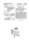
When the ejection stroke does occur, CPU 100 will
input the stroke duration and pulse count Cp, as called
the latter block CPU 100 increments counter A, and
then proceeds to a comparison block 254 which com~
pares the value of A to a test value, in this case 2. If the
content of counter A is not equal to 2, CPU 100 is di
rected to block 256, which calls for the deletion of the
pulses-per-second values for the two strokes that are
furthest from the mean value of PN. CPU 100 is then
for by block 220, and then fetch the minimum pulse
count Cm per block 222. As indicated by comparison
block 224, if the actual pulse count value CF is greater
This in effect gives the instrument a second chance to
find an acceptable set of pulses-per-second values
than or equal to the minimum value Cm, CPU will go on
to compute and store the pulses-per-second value PNfor
the just-completed stroke, as indicated by block 226. If,
on the other hand, actual pulse count C1, is less than the
minimum pulse count Cm, the operator will be informed
of this fact by the message “incomplete stroke at setting
1”, as called for by block 228. This requires the operator
rupted as block 248 directs CPU 100 to a block 252. In
returned to block 246 to compute a new value for CV.
among the values produced by the operator at syringe
setting N.
If, however, the program attempts to reach block 256
a second time, i.e., attempts to delete data for two fur
to repeat the stroke in a manner which will produce a
ther strokes, it will be prevented from doing so by com
parison block 254, which then directs CPU 100 to a
further block 258. As a result ofencountering block 258,
a counter B is incremented to signal the fact that, after
two attempts to compute an acceptable Cyvalue, CPU
higher turbine output pulse count. In addition to alert
100 was unable to do so. Under the latter condition,
ing an operator of the fact that he may not be operating
CPU 100 is directed to comparison block 260 which,
the syringe between its true innermost and outermost
unless counter B has a value of three, reaches block 262
positions, blocks 224 and 228 may be used to help iden
which, in turn, causes the operator to be informed that
tify circuit failures such as the failure of one of the 25 it is necessary for him to re-enter the entire sequence of
LED’s or phototransistors within turbine 38.
strokes at setting N. Following the outputting of this
Based on the pulses-per-second value PNthat is com
information, the program re-enters the stroke entry
puted in block 226, CPU 100 next fetches the maximum
sequence at block 210 via branch connector Z.
and minimum acceptable pulses-per-second values
In those rare instances in which three complete sets of
acceptable strokes at setting N fail to result in an accept
PM“; and PNmin for N: l, as called for by block 230,
and compares PN thereto in blocks 232 and 234 to deter
able coef?cient of variation, then comparison block 260
mine if it is between them. These comparisons together
will respond to the 3 in counter B to direct CPU 100 to
a block 264. The latter block causes CPU 100 to inform
assure that actual pulses-per-second value PN lies be
tween the end points of the line segment for which
calibration data is being sought. In the event that this
dual test is passed, stroke count Cs is incremented in
block 236 and then compared against the total number
of acceptable strokes that are required at setting N, as
called for by block 238. If the required number of ac
ceptable strokes has not yet been made, block 238 di
the operator that he should consult the user’s manual
because of the probability of a failure within the instru
ment. Once this fault is corrected, the operator may
then restart the calibration sequence at block 200 and
repeat the process to establish an acceptable set of val
ues for the coef?cient of variation for each syringe
setting.
'
Returning to the desired ?ow of the calibration se
quence at block 248, if coef?cient of variation CVis less
Alternatively, if the actual pulses-per-second value
than or equal to CVmax, comparison block 248 will cause
CPU 100 to proceed to block 250. In the latter block
PN for a particular stroke fails to fall within the range
called for by blocks 232 and 234, stroke count C, is not 45 CPU 100 is caused to calculate a correction factor (in a
manner that will be described presently) and thereby
incremented, and CPU 100 is directed to one of blocks
determine the position of the segment of interest of
240 and 242. The applicable one of these blocks informs
curve C2 with respect to the corresponding segment of
the operator whether the just-completed stroke was
unacceptable as a result of being too fast or as a result of
curve C1. After the calculation of the correction factor
being too slow. In either case, CPU 100 is returned to
FcNfor setting N: 1, CPU 100 is directed to a compari
son block 270 which compares the then current value of
block 212, via branch connector y, to call for another
N with the desired maximum value thereof. If the value
stroke.
of N is not equal to the maximum value (in the preferred
The above-described stroke entry sequence is re
embodiment 3), CPU 100 is directed to a block 272
peated as necessary until the actual number of accept
able strokes is equal to the required number of strokes; 55 which increments N and returns CPU 100 to block 202
rects CPU 100 back to block 212, via branch connector
y, to initiate a request for additional strokes.
in the present example this number is (T + 1) since Cs
via branch connector X. This causes CPU 100 to re
was initially set to 1 in block 210. When the required
quest turbine data for another syringe setting so that it
number is reached, comparison block 238 directs CPU
may determine the position of a new line segment on
curve C2, such as segment B’. When this occurs, the
100 to block 244 to clear a counter A which will be
described presently. Thereafter, as called for by block 60 above-described stroke entry sequence will be repeated
for the new syringe setting.
246, CPU 100 calculates the coef?cient of variation CV
When correction factors have been produced for
of the pulses-per-second values for the accepted strokes
each of the desired number of line'segments of curve
by calculating the standard deviation thereof and divid
C2, CPU 100 is directed to block 274. This block causes
ing the same by the mean value thereof (a calculation
that is familiar to those skilled in the art) and fetches the 65 CPU 100 to calculate the intercept values b’N for each
line segment of curve C2. The latter intercepts, together
maximum acceptable value for CV, CVmax.
with the stored slopes of the line segments of curve C1,
If Cy is greater than the maximum acceptable value
provide the m and b values that are necessary to com
therefor Cvmax, the desired flow of the program is inter
15
4,448,058
16
plete the slope-intercept form equations for the line
correction factors alone may be stored for use in gener
segments of curve C2. As will be explained in greater
ating the equations for the line segments of curve C2
detail presently, these calculations involve the multipli
from those of curve C1 on an as-needed basis. In partic
ular, when an equation for a segment of curve C2 is
cation of the intercepts for the line segments of curve
C1 by their respective correction factors. Block 274 is
needed, it may be produced by multipying the intercept
followed by block 276 which causes CPU 100 to actu
of the equation for the corresponding segment of Curve
C1 by the applicable correction factor. The advantage
ally generate and store the slope-intercept ?rm equa
tions which together de?ne piecewise linear curve C2.
of the latter approach is that fewer memory locations
Once the latter curve is stored, the volume calibration
sequence is complete; CPU 100 is then in condition to
are required to store the information necessary to make
the desired piecewise linear approximation available to
‘the instrument. The two approaches to storing the
proceed with unrelated calibration procedures, such as
zeroing, or with the taking of actual measurements.
piecewise linear approximation are equivalent, how
The manner in which the correction factors are cal
culated for the line segments of curve C2 will now be
described. Referring to FIG. 2, it will be seen that line
segment B of curve C1 comprises that portion of a line
ever, since both can be used in the above-described
manner to interpret the gas concentration measure
ments made by gas analysis section 12.
yB=mBxB+bB which lies between pulses-per-second
values Pgmax and Pgmin. The latter equation is in the
previously mentioned slope/intercept form in which
my represents the slope of the line and b5 represents the
C are in general suf?ciently different from one another
that it is desirable to have independently determined
correction factors for use in ?xing the intercepts of line
The intercepts of piecewise linear segments A, B and
20
segments A’, B’ and C’. For the steepest piecewise lin
intercept of that line on the vertical or Y axis. The
graphical signi?cance of my and by are shown on the
dotted line extension of curve B of FIG. 2 The correc
ear segments, such as D and E, however, it is possible to
C2. This relationship is expressed in equation (1) of
FIG. 2. The corrected intercept b'B' together with slope
desirable because it makes unnecessary either the use of
a separate calibration syringe with a smaller volume or
segment B of curve C1 to be shifted up or down to a
are derived from measurements made for other line
segments. In both cases, the instrument is made able to
determine the volume of gas delivered during a breath
with an accuracy that is substantially greater than that
use the same correction factor that was determined in
connection with line segment C, without a signi?cant
tion factor FCB for segment B is that number which,
loss
of accuracy. This application of the correction
when multiplied by intercept by of curve C1, yields the 25
factor for line segment C to line segments D and E is
value of the intercept b’B' of line segment B’ of curve
the use of extremely slow piston speeds. The latter
mg (which may reasonably be assumed to be the same
for curves C1 and C2) is suf?cient to specify the equa 30 approaches are nevertheless available should they be
desirable in particular applications. It will therefore be
tion for line segment B’ of curve C2 between maximum
understood that the present invention contemplates
and minimum pulses-per-second values Pym,“ and
both
embodiments in which the correction factors for
PBmin
all line segments are determined independently, and
From the foregong it will be seen that correction
factor FCB is a number which, in effect, allows line 35 embodiments in which one or more correction factors
new position in which it more nearly reflects the re
sponse of the actual turbine in its then current condi
tion. The correction factors F94 and Fcc for line seg
ments A and C will be understood to operate in a similar 40 exhibited by previously available instruments.
It will be understood that since the volume calibra
manner to shift those line segments to new positions in
tion process described above is carried out on a regular
which they also reflect the operation of the turbine in its
basis, the instrument of FIG. 1 is regularly provided
then current condition.
with a fresh nonlinear turbine characteristic curve such
Referring to equation (2) of FIG. 2, there is shown
the algebraic expression that is used to calculate correc 45 as C2 of FIG. 2. This assures that the instrument always
has available to it information concerning the then cur
tion factors such as FCB. In equation (2), Pgmm is the
rent response of turbine 38, even as that response
average pulses-per-liter value that is associated with an
acceptable set of turbine output data taken with the
syringe at a setting such as B. Pgmlc is the pulses-per
liter value, from curve C1, which is associated with the
average of the measured pulses-per-second values.
Equation (2) simply combines these two numbers to
produce a scaling factor that allows any point on line
segment B’ of curve C2 to be expressed in terms of the
corresponding point on line segment B of curve C1.
55
In operation, the calculation called for by equation
changes with time, wear and the accumulation of dirt.
Thus, the bene?ts of the invention are available on a
continuing basis.
In view of the foregoing, it will be seen that the vol
ume calibration method and apparatus of the invention
includes both improvements in the apparatus for deliv
ering calibration gas (the syringe) and in the method
and apparatus for using that gas to volume calibrate the
instrument. Together, these improvements result in an
instrument which, with each calibration, re?ects not
only the nonlinear response of a typical turbine, but also
the nonlinear response of the particular gas turbine in its
(2) is carried out by CPU 100 each time that it encoun
ters block 250 of FIG. 60. Once CPU 100 has encoun
tered block 250 once for each line segment for which a
correction factor is required, i.e., once all of the correc 60 then current condition. As a result, the overall accuracy
of all measurements which are made with the instru
tion factors are available the latter may be combined
ment are signi?cantly improved.
with the previously stored intercepts of the respective
What is claimed is:
line segments of curve C1 in accordance with equation
1. In. a gas analysis instrument ofthe type having at
(1), as CPU 100 encounters block 274 of FIG. 6c. Fi
nally, as CPU 100 encounters block 276, these inter 65 least one gas analyzer for measuring the concentration
cepts may be combined with the previously stored re
of a component of interest in human breath, and a gas
turbine for producing a number of output pulses that
spective slope values to produce andstore the parame
ters of the equations for curve C2. Alternatively, the
varies in accordance with the volume and rate of flow
4,448,058
17
of human breath therethrough, the improvement com
prising:
(a) ?rst means for storing a piecewise linear approxi
mation of the response of the gas turbine,
(b) second means responsive to the number of output 5
pulses produced by the turbine for determining the
operating point of the turbine on the stored approx
imation, and
‘
(c) third means responsive to the stored approxima
tion and the output of the second means for provid
ing volume data for a breath.
2. The instrument of claim 1 in which the ?rst means
stores the piecewise linear approximation by storing the
18
(a) ?rst means for storing the information necessary
to make available a piecewise linear representation
of the response of the gas turbine, said representa
tion relating the volume of breath ?owing through
the turbine to the rate of ?ow of that breath there
through,
(b) a breath switch connected in series with the gas
turbine to generate an output signal indicative of
the duration of a breath,
(c) second means responsive to the output signal of
the turbine and the output signal of the breath
switch for determining the rate of ?ow of a breath,
and
.
parameters of the equations for a plurality of linear
segments, together with the maximum and minimum 15
values between which respective linear segments are
(d) third means responsive to the ?rst means and the
second means for determining volume data for a
applicable.
13. The instrument of claim 12 in which the ?rst
3. The instrument of claim 2 in which the approxima
tion gives the number of pulses-per-liter produced by
the turbine as a function of the number of pulses-per
second produced thereby.
'
4. The instrument of claim 3 in which the second
breath.
.
means stores the piecewise linear representation by
storing the parameters of the equations for a plurality of
line segments, together with the ranges of ?ow rates
over which those line segments are applicable.
14. The instrument of claim 13 in which the third
means determines the volume data for a breath by (a)
means determines said operating point by dividing the
substituting into one of said equations the rate of ?ow
total number of turbine output pulses by the time inter
val during which those pulses occurred to produce a 25 determined by the second means, and (b) solving said
equation for said volume data.
pulses-per-second value. ~
‘
5. The instrument of claim 4 in which the third means
15.. The instrument of claim 12 or 14 in which the
includes (a) means for comparing the pulses-per-second
output signal of the turbine comprises a series of pulses
value with said maximum and minimum values to iden
and in which the second means includes (a) a counter
tify the applicable linear segment, (b) means for combin
for counting the number of pulses produced by the
ing the pulses-per-second signal with the respective
turbine during the time that the breath switch is open,
and (b) means for dividing the number in said counter
by the time that the breath switch is open to determine
linear segment to determine the associated pulses-per
liter value, and (0) means for determining the volume of
a breath from said pulses-per-liter value.
6. The instrument of claim 4 in which the third means 35
includes (a) means for combining said pulses-per-second
the rate of ?ow of a breath.
16. The instrument of claim 12 including means for
storing the information necessary to make available a
value with the stored approximation to produce a
second piecewise linear representation of the response
pulses-per-liter value, and (b) means for combining said
pulses-per-second value with said pulses-per-liter value
of an average turbine of the class of turbine to which the
‘to determine the liters-per-second value for a breath.
7. The instrument of claim 1 in which the linear ap
17. The instrument of claim 16 in which the stored
piecewise linear representation is derived from the sec
ond piecewise linear representation on the basisof vol
ume data taken during calibration.
18. The instrument of claim -12 in which thevolume
proximation gives the number of pulses-per-liter pro
duced by the turbine as a function of the number of
pulses-per-second produced thereby.
gas turbine belongs.
.
8. The instrument of claim 7 including a breath switch 45 data is the volume of a breath.
19. The instrument of claim 12 in which the volume
connected in series with the gas turbine to produce a
data is the volume rate of ?ow of a breath.
signal indicative of the duration of a breath.
20. A method for volume calibrating a gas analysis
9. The instrument of claim 8 in which the second
instrument of the type having (a) a source for providing
means includes a counter for counting the output pulses
a known volume of calibration gas, and (b) a gas turbine
produced by the turbine, said counter being enabled by
for providing an output signal that varies in accordance
the breath duration signal from the breath switch.
with the volume and rate of ?ow of gas therethrough,
10. The instrument of claim 9 in which the second
said method including the steps of:
means includes means for dividing the number of output
pulses produced during a breath by the duration of that
breath to produce a pulses-per-second value for use in 55
determining said operating point.
11. The instrument of claim 10 in which the third
means includes means for determining a pulses-per-liter
value from said pulses-per-second value and the stored
approximation, and means for combining said pulses
per-liter value with said pulses-per-second value to
determine the liters-per-second value for a breath.
12. In a gas analysis instrument of the type having at
least one gas analyzer for measuring the concentration
of a compound of interest in human breath, and a gas 65
turbine for producing an output signal that varies in
(a) storing a ?rst piecewise linear approximation of
the output response of a typical turbine of the class
of turbine to which said gas turbine belongs,
(b) directing said known volume of gas through the
turbine at a plurality of rates of ?ow which corre
spond to a plurality of the linear segmentsof the
piecewise linear approximation and storing data
indicative of the resulting turbine output signals,
(0) combining the approximation of step (a) with the
data stored during step (b) to produce a second
piecewise linear approximation of the output re
sponse of the gas turbine, and
((1) making the second piecewise linear approxima
accordance with the volume and rate of ?ow of breath
tion available ‘for use in interpreting measurements
therethrough, the improvement comprising:
made by the instrument.
.
4,448,058
19
20
r
. 21. The method of claim 20 in which the ?rst stored
?owing through the turbine to the rate of ?ow of gas
approximation gives the volume of gas ?owing through
therethrough.
the turbine as a function of the rate of ?ow of gas there
30. The calibration apparatus of claim 28 in which the
turbine produces an output signal comprising a succes
sion of pulses, and in which the ?rst and second linear
through.
22. The method of claim 20 or 21 in which the ?rst
stored approximation is stored by storing the parame
approximations relate the pulses-per-liter values for gas
?ow through the turbine to respective pulses-per
ters of the equations for a plurality of linear segments,
together with the ranges of How rates over which those
linear segments are applicable.
second values.
31. The calibration apparatus of claim 30 in which the
?rst and second linear approximations are stored by
storing the parameters of the eauations for a plurality of
_
23. The method of claim 22 in which the second
approximation is produced by changing the parameters
of the equations of the linear segments of the ?rst ap
proximation to re?ect the datareceived during step (b).
linear segments, together with the ranges of pulses-per
second values associated with those linear segments.
24. The method of claim 23 in which the data associ
ated with a ?ow of said known volume of gas through
the turbine is accepted for use in producing the second
32. The calibration apparatus of claim 31 in which the
parameters of the equations of at least one of the linear
segments of the second linear approximation are pro
piecewise linear approximation only if the ?ow rate
duced by combining the parameters of the correspond
ing linear segment of the ?rst linear approximation with
associated therewith is within a predetermined range of
acceptable ?ow rates.
a correction factor that is a function of (a) the total
25. The method of claim 20 in which said known 20 number of pulses produced as said known volume of gas
volume of gas is directed through the turbine a plurality
flows through the turbine, and (b) the time interval
of times at each ?ow rate, and in which said stored data
during which the latter pulses occurred.
is averaged before being used in producing the second
33. The calibration apparatus of claim 28 in which the
approximation.
?rst and second linear approximations are stored by
26. The method of claim 20 in which the turbine 25 storing the parameters of the equations for a plurality of
produces an output signal comprising a succession of
linear segments, together with the ranges of ?ow rates
pulses, and in which the ?rst linear approximation re
that are associated with those linear segments.
lates the number of pulses per unit volume of gas ?ow to
34. The calibration apparatus of claim 33 in which a
the number of pulses-per-second of gas ?ow.
parameter of at least one linear segment of the second
27. The method of claim 26 in which the position of 30 linear approximation is derived from the parameter of
a linear segment of the second linear approximation is
the corresponding linear segment of the ?rst linear ap
determined by (a) measuring the pulses per unit volume
proximation by applying a correction factor that is
that result from the ?ow of said known volume of gas
based on the difference between the stored response of
through the turbine, (b) dividing the total number of
a typical turbine and the measured response of the ac
pulses that result from the ?ow of said known volume 35 tual turbine.
of gas through the turbine by the duration of said ?ow
to determine a pulses-per-second value, (c) calculating a
correction factor from the measured number of pulses
per unit volume and the number of pulses per unit vol
ume called for by the ?rst linear approximation at the
same pulses-per-second value, and (d) applying said
35. In a gas volume calibration apparatus for respira
tory gas analysis instruments of the type including (a) a
calibration syringe having a housing and a piston slid
ably mounted therein, said syringe being adapted to
provide a known volume of gas as the piston is moved
between predetermined ?rst and second positions, and
correction factor to one of the linear segments of the
(b) a gas turbine for providing a number of output pulses
that varies in accordance with the rate at which said
?rst linear approximation to position the corresponding
linear segment of the second linear approximation.
volume of gas ?ows therethrough, the improvement
28. In a gas volume calibration apparatus for a gas 45 characterized by:
analysis instrument of the typeincluding (a) a source for
(a) a breath switch, connected in series with the tur
supplying a known volume of calibration gas, (b) a gas
bine, for providing an output signal indicative of
turbine for providing an output signal that varies in
the duration of a stroke of the piston,
accordance with the volume and rate of ?ow of gas
therethrough, and (c) a control circuit connected to the 50
turbine, the improvement characterized by: (a) means in
the control circuit for storing a ?rst piecewise linear
approximation of the response of a typical turbine of the
class of turbine to which the gas turbine belongs,
(b) means in the control circuit for receiving the 55
output signal of the gas turbine as said known vol
(b) ?rst means for receiving the turbine output pulses
produced during a stroke of the piston and the
output signal of the breath switch and for generat
ing an actual ?ow rate signal indicative of the
speed of the stroke,
(0) second means for storing maximum and minimum
acceptable values for said ?ow rate signal, and
(d) third means for comparing the actual ?ow rate
ume of gas is directed therethrough at rates of ?ow
that correspond to at least two different linear
signal with said maximum and minimum acceptable
values and for accepting the actual ?ow rate signal
segments of the piecewise linear approximation,
for use in calibrating the instrument only if it com
pares favorably with said maximum and minimum
values.
36. The gas volume calibration apparatus of claim 35
in which maximum and minimum acceptable values are
stored for each of a plurality of stroke speeds, and in
65 which the third means compares the actual ?ow rate
and
(0) means in the control circuit for modifying said
?rst piecewise linear approximation in accordance
with the output signals produced by the turbine
during calibration to produce a second piecewise
linear approximation of the response of the gas
turbine.
29. The calibration apparatus of claim 28 in which the
?rst linear approximation relates the volume of gas
signals for a plurality of stroke speeds with respective
maximum. and minimum acceptable values for those
stroke speeds.
21
4,448,058
37. The gas volume calibration apparatus of claim 36
in which a predetermined number of strokes having
acceptable ?ow rate signals must occur before the in
strument is calibrated at the ?ow rate corresponding to
number of output pulses that varies in accordance with
the volume and rate of ?ow of gas therethrough, said
method including the steps of:
(a) establishing a plurality of pairs of maximum and
minimum acceptable pulses-per-second values cor
the respective stroke speed.
38. The gas volume calibration apparatus of claim 37
in which the ?ow rate values of sid predetermined num
ber of strokes are averaged to produce an average flow
responding to a pluraliy of ?ow rates for said
rate value for use in calibration.
known volume of gas through the turbine,
(b) moving the piston in a succession of strokes to
39. The gas volume calibration apparatus of claim 38
in which said average ?ow rate value, together with the
volume of the calibration syringe, determine the posi
tion of a line segment that approximates the response of
cause said known volume of gas to ?ow through
the turbine at a ?rst estimated ?ow rate,
(0) calculating the pulses-per-second values associ
the turbine between said maximum and minimum ac
ceptable values.
22
calibration syringe for providing a known volume of
gas, said syringe having a housing and a piston slidably
mounted therein, and (b) a gas turbine for providing a
15
ated with the strokes of step (b),
(d) comparing the resulting pulses-per-second values
40. The gas volume calibration apparatus of claim 36
including an improved calibration syringe having con
trol means for selectably controlling stroke speed.
to a ?rst pair of maximum and minimum acceptable
pulses-per-second values,
(e) storing those pulses-per-second values which
41. The gas volume calibration apparatus of claim 40
in which the syringe includes an aperture for admitting
compare favorably with said ?rst pair of maximum
ambient air into the region behind the trailing edge of
and minimum acceptable values for use in calibrat
ing the instrument, and
(f) repeating steps (b) through (e) for at least a second
the piston, and in which the control means limits the
stroke speed of the syringe by limiting the rate at which
ambient air can ?ow through said aperture.
estimated ?ow rate and a second pair of maximum
and minimum acceptable pulses-per-second values.
42. The gas volume calibration apparatus of claim 41 25
in which the control means includes a plate having at
47. The method of claim 46 including the step of
calculating the average of the pulses-per-second values
least one hole which may be rotated into alignment with
for the acceptable strokes performed at each estimated
said aperture.
?ow rate.
43. The gas volume calibration apparatus of claim 35,
40, 41, or 42 in which the syringe is provided with a 30 48. The method of claim 47 including the step of
determining the coef?cient of variation of the pulses
calibration gas inlet and a calibration gas outlet that are
per-second values for the acceptable strokes performed
separate from one another, and in which the arrival of
at each estimated ?ow rate, and rejecting those accept
the piston in said second predetermined position posi
able values if the coef?cient of variation therefor is
tively shuts off the flow of calibration gas in at least said
outlet.
35 greater than a predetermined maximum coef?cient of
variation.
49. The method of claim 46 including the steps of
44. The gas volume calibration apparatus of claim 35
including means for communicating to a user the need
communicating to a user the need for faster strokes if
for faster strokes if the ?ow rate signal for a stroke is
the the pulses-per-second value for a stroke is less than
less than said minimum acceptable value, and for com
municating to a user the need for slower strokes if the 40 the minimum acceptable value therefor, and of commu
nicating to a user the need for slower strokes if the
?ow rate signal for a stroke is greater than said maxi
pulses-per-second value for a stroke is greater than the
mum acceptable value.
maximum acceptable value therefor.
45. The gas volume calibration apparatus of claim 35
50. The method of claim 46 or 49 including the step of
or 44 including means for informing a user of the num
counting the number of acceptable strokes and commu
ber of acceptable strokes that he has performed.
nicating that number to the operator after each stroke.
46. A method for providing volume calibration data
#
t
*
i
t
to a gas analysis instrument of the type including (a) a
50
55
65