1
Modbus ASCII / RTU to DF1 Converter
SGW1-MB-DF1
User´s Manual
Internet Enabling Solutions
www.exemys.com
SGW1-MB-DF1 User Manual
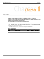
Introduction
Exemys Products are in constant evolution to satisfy our customer needs. For that reason, the specifications
and capabilities are subject to change without prior notice.
Updated information can be found at www.exemys.com
Copyright © Exemys, 2006. All Rights Reserved.
Rev. 1.4.0
www.exemys.com
Rev. 1.4.0
Page 2
SGW1-MB-DF1 User Manual
Introduction
Index
INTRODUCTION
5
GETTING STARTED
6
2.1 Wiring instructions______________________________________________________ 6
2.2 Device configuration ____________________________________________________ 6
2.2.1
2.2.2
2.2.3
Opening the Serial console
Serial Ports Configuration
Configuration of the Translation Tables
7
7
8
2.3 Ready to go ___________________________________________________________ 11
ADVANCED TOPICS
12
3.1 Modbus related commands _______________________________________________ 12
3.2 DF1 related commands __________________________________________________ 13
3.3 Tables related commands_________________________________________________ 14
3.4 General commands _____________________________________________________ 16
THE EMBEDDED MODBUS SLAVE
18
4.1 Enabling the slave ______________________________________________________ 18
4.2 Monitoring and controlling built-in digital inputs and outputs______________________ 18
A. CABLING
19
A.1.
Power ____________________________________________________________ 19
A.2.
Ground ___________________________________________________________ 19
A.3.
Digital Inputs_______________________________________________________ 19
A.4.
Digital Outputs _____________________________________________________ 20
A.5.
RS-232 Ports _______________________________________________________ 21
A.5.1. Modbus/console port
A.5.2. DF1 port
www.exemys.com
21
22
B. MONITORING THE DEVICE THROUGH THE BUILT-IN LEDS
24
C. CONFIGURING FLEXLOGIX AND CONTROLLOGIX PLCS
25
Rev. 1.4.0
Page 3
SGW1-MB-DF1 User Manual
Introduction
Figures
Figure 1 - Wiring instructions _________________________________________________________________6
Figure 2 - Handling incoming Modbus Requests __________________________________________________11
Figure 3 - Power Input Connection Scheme ______________________________________________________19
Figure 4 - Digital Input connected to an external device with _________________________________________20
Figure 5 - Digital input connected to a dry contact_________________________________________________20
Figure 6 - The load and the Exemys device using __________________________________________________21
Figure 7 - The load and the Exemys device share the power supply ____________________________________21
Figure 8 - Connecting the computer to the SGW1-MB-DF1___________________________________________22
Figure 9 - Connecting a Micrologix 1000 processor to the SGW1-MB-DF1 _______________________________22
Figure 10 - Connecting an SLC 500 processor to the SGW1-MB-DF1____________________________________23
Tables
Table 1 - Available Models ___________________________________________________________________5
Table 2 - Digital Inputs - Technical Specifications__________________________________________________20
Table 3 – Digital Outputs – Technical Specifications _______________________________________________21
Table 4 - Meaning of the LEDs blinking _________________________________________________________24
Listings
Listing 1 - Welcome message _________________________________________________________________7
Listing 2 - Modbus port configuration ___________________________________________________________7
Listing 3 - DF1 port auto detection _____________________________________________________________8
Listing 4 - DF1 Error detection and Modbus mode __________________________________________________8
Listing 5 - N Files table ______________________________________________________________________9
Listing 6 - Insert records in the N table and B table ________________________________________________10
Listing 7 - Contents of all the tables ___________________________________________________________10
Listing 8 - Modbus related commands__________________________________________________________12
Listing 9 - DF1 related commands _____________________________________________________________13
Listing 10 - Tables related commands __________________________________________________________15
Listing 11 - General commands_______________________________________________________________16
Listing 12- The list command ________________________________________________________________17
www.exemys.com
Rev. 1.4.0
Page 4
SGW1-MB-DF1 User Manual
Introduction
Chapter 1
Chapter
Introduction
Thank you for your purchase! SGW1-MB-DF1 is a Modbus ASCII/RTU to DF1 gateway.
SGW1-MB-DF1 lets you gain access to a wide range of industrial DF1-talking devices just by using
Modbus, a de facto standard in the industrial field.
As a bonus, SGW1-MB-DF1 incorporates the following features:
An embedded Modbus slave, which provides built-in digital I/O for remote sensing and
controlling (four inputs and four outputs).
A serial text-based console, that allows full configuration of the device.
Table 1 - Available Models
www.exemys.com
Model
Serial Protocols
SGW1 - 2044 - MB - DF1
Modbus ASCII/RTU
DF1 Full Duplex
Rev. 1.4.0
Inputs
Outputs
Serial Ports
4
4
(2) RS-232
Page 5
SGW1-MB-DF1 User’s Manual
Getting Started
Chapter 2
Chapter
Getting Started
This chapter shows how to get your new SGW1-MB-DF1 started. It focuses on the main features
of this product, that is, Modbus ASCII/RTU to DF1 protocol conversion. For clarity, it is based on
an example. Learn how to connect the cables, power up and configure the device in minutes.
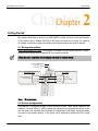
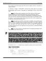
2.1 Wiring instructions
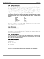
Power supply and RS-232 ports: These signals are located in the top green connectors. Figure 1
shows the basic wiring. Refer to Appendix A if you need more details.
Detach the green connectors before screwing the cables to ease the wiring.
TIP
Power Supply Vin
9-30 VDC
9-26 VAC Vin
DF1 PORT
MODBUS PORT *
To the computer´s
RS-232 port
To GND
To GND
To TxD
To RxD
To TxD
To RxD
To PLC´s
RS-232 port
* This is also the console port
Figure 1 – Wiring instructions
2.2 Device configuration
SGW1-MB-DF1 is configured through a serial text-based console. Under regular operation, this
console is not used. Indeed, it will be opened only when you start operating the device for the
first time and if you eventually need to modify its configuration in the future. Configured values
are stored in non-volatile memory, so the device can be powered off without the risk of losing
data.
www.exemys.com
Rev. 1.4.0
Page 6
SGW1-MB-DF1 User’s Manual
Getting Started
2.2.1 Opening the Serial console
The serial console is physically tied to the same port used to process Modbus traffic. Then, you do
not need to remove/replace the cables every time you configure the device.
When SGW1-MB-DF1 boots up, it enables a seven-seconds window to open the configuration
console. Within this lapse, no Modbus requests will be processed. However, if the user opens the
console, it will be kept in that state until the console is explicitly closed. If the seven-seconds
window elapses without receiving any request that opens the console, the device will start
working in gateway mode (e.g. converting from Modbus ASCII/RTU to DF1).
To configure the device, first open a terminal in your computer (HyperTerminal or alike). Configure
the terminal to open the same RS-232 port connected to the SGW1-MB-DF1. Set up the program
as follows:
Data bits
8
Parity
None
Stop bit
1
Flow Control
None
Baud rate
9600bps
Then, power the device on and type CFG <ENTER> within the first seven seconds. You should
receive a welcome message on the terminal screen:
Listing 1 - Welcome message
SGW1-MB-DF1 - Exemys (v1.2):
-------------------------->
Now the device is running in configuration mode. If you cannot see a message as above, check
the wiring and terminal configuration.
2.2.2 Serial Ports Configuration
You have to configure both RS-232 ports to work with your Modbus master (computer side) and
the DF1 device (PLC side). Let’s configure the Modbus port first. Assuming baud rate=115200 bps
and no parity, type the following commands:
Listing 2 - Modbus port configuration
SGW1-MB-DF1 - Exemys (v1.2):
-------------------------->mbbaud:115200
OK, Baud rate:115200
>mbparity:n
OK, Parity:NONE
>
Now let’s set the DF1 port. An auto detection feature configures the device automatically:
www.exemys.com
Rev. 1.4.0
Page 7
SGW1-MB-DF1 User’s Manual
Getting Started
Listing 3 - DF1 port auto detection
>autodetect
Please wait while detecting configuration...
Baud rate: 19200
Parity: NONE
>
If no PLC is detected, check the cable that connects SGW1-MB-DF1 to the PLC and retry.
Next, let’s set the BCC/CRC (error detection mechanism in DF1 protocol). Note that this parameter
must match the one configured on the PLC. Also, we have to specify the Modbus mode, that is,
ASCII or RTU:
Listing 4 - DF1 Error detection and Modbus mode
>error:crc
OK, Error detection mechanism:CRC
>mbmode:r
OK, Mode:RTU
>
Now we are done with ports configuration. In the next section we will go on with the tables that
tell the device how to perform the translation between both protocols.
2.2.3 Configuration of the Translation Tables
In order to address PLC data, SGW1-MB-DF1 maintains some internal Translation Tables between
Modbus and DF1 protocols. The tables are applied to internal Files, but not to the Input/Output
modules connected to the PLC.
NOTE
Many newer PLCs (such as FlexLogix and ControlLogix) do not provide (as a factory default)
compatibility with the commands requested by the SGW1-MB-DF1. However, they include a
mechanism to make themselves downwards compatible with older PLCs and with the SGW1-MBDF1. Please refer to Appendix C if you are attempting to connect one of this PLCs to the SGW1MB-DF1.
Henceforth, a real situation is proposed. It might differ slightly from your actual configuration,
though we think of a study case as the best way to get in touch with your new protocol converter.
There is PLC that runs a program. We want to make some data available to one Modbus master
by means of the SGW1-MB-DF1. The PLC has four Input/Output boards. These boards have the
following I/O capabilities:
www.exemys.com
Module
Characteristics
Capacity
1
2
3
4
16 Digital Inputs
32 Digital Outputs
4 Analog Inputs
32 Digital Outputs
1 word
2 words
4 words
2 words
Rev. 1.4.0
Page 8
SGW1-MB-DF1 User’s Manual
Getting Started
It is required to access not only I/O data, but it is also important to monitor some words,
contained in two N Files (File Numbers 7 and 10) and on some read/write bit variables, contained
in one B File, whose File Number is 3.
First, we may check that tables are clean at start-up, for example we check the N Files Table:
Listing 5 – N Files table
>tblview:n
File
| Holding
Number | Register
_____________________
*** Table empty ***
As a factory reset, those tables that are configurable will be empty.
Input and outputs modules connected to the PLC do not require any further configuration in the
SGW1-MB-DF1. In order to access the modules, the end user will have to issue appropriate
Modbus requests, thus the protocol converter will translate them into DF1 commands which can
be understood by the PLC.
The mapping between Modbus and DF1 protocol for Input/Output modules is straightforward. It is
summarized in the following rules:
- Input modules can be read through Inputs Status or Input Register.
- Output modules can be read through Coil Status or Holding Register.
- Each Holding Register or Input Register is associated to one word (16 bits). Thus, each
word contained in a module is assigned to one Modbus location, either Holding Register
or Input Register (generically, one “Register” location).
- Each Coil Status or Input Status is associated to one bit. Thus, each bit contained in a
module is assigned to one Modbus location, either Coil Status o a Input Status
(generically, one “Status” location).
- The multiple coils write command only allows a write to a single coil.
- Modules with less than one word use one complete Modbus “Register”.
- Requests to “Register” locations up to address 64 are assumed to be requests for the
modules.
- Requests to “Status” locations up to address 1024 are assumed to be requests for the
modules.
The modules will be addressed as shown in the following table, according to the rules above.
Module
1
2
3
4
www.exemys.com
Coil Status
Input Status
Holding Register
10001-10016
Input Register
30001-30001
00001-00032
40001-40002
10017-10080
30002-30005
00033-00064
40003-40004
Rev. 1.4.0
Page 9
SGW1-MB-DF1 User’s Manual
Getting Started
For example:
- To read output 20 in module 2, ask for Coil Status 00021.
- To read word 3 in module 3, ask for Input Register 30004
SGW1-MB-DF1 maintains three internal tables:
N table: lets you add and remove N Files. Each element in an N File is 16-bits wide.
B table: lets you add and remove B Files. Each element in a B File is 1-bit wide.
S table: stores the boundaries for the S File, the area where many PLCs store statistics data.
N and B tables are user configurable, but the S table is fixed.
The data required to insert records into the N or B table are
which table to use (either B or N)
row number
File Number (this number will match the one configured on the PLC)
Going on with the example, we insert the remaining information:
Listing 6 - Insert records in the N table and B table
>tblins:n,0,7
Table)
Record inserted
// File N, File Number 7, in record 0 (N
>tblins:n,1,10
1 (N Table)
Record inserted
// File N, File Number 10, in record
>tblins:b,0,3
Table)
Record inserted
// File B, File Number 3, in record 0 (B
Now we check all the tables, by calling the tblview command omitting any other parameter.
Listing 7 – Contents of all the tables
>tblview
N Table
Length: 2
File
| Holding
Number | Register
_____________________
7
| 40192 40447
10
| 40448 40703
B Table
Length: 1
File
|
Coil
Number |
Status
_____________________
3
| 01152 05247
S Table
www.exemys.com
Rev. 1.4.0
Page 10
SGW1-MB-DF1 User’s Manual
Getting Started
Length: 1
File
|
Input
Number |
Status
_____________________
2
| 30192 30448
>
Note that Modbus addresses are assigned by the SGW1-MB-DF1 just after inserting records into
the tables. This information will have to be provided to the Modbus master to poll the PLC. A
request that cannot be translated by the device will cause a translation error. In turn, SGW1-MBDF1 will report a Modbus exception (if exceptions are enabled).
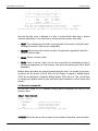
2.3 Ready to go
After filling the tables with the appropriate information, the device is ready to accept polls from a
Modbus master. Power off and on the device, wait al least seven seconds (to skip the
configuration mode) and poll the PLC as if it had an actual Modbus port. Following the example
proposed in this chapter, the Modbus master should be set as:
Databits: 8
Baudrate: 115200
Parity: None
Unit ID: 1
Modbus mode: RTU
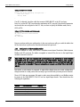
Recall that the only Modbus locations available to the master are those assigned by SGW1-MBDF1. Figure 2 illustrates how Modbus requests are handled by the device.
Modbus Request
Table Look Up
Modbus Master
Modbus DF1
Protocol Translation
DF1 Request
PLC
DF1 Reply
Modbus Reply
DF1 Modbus
Protocol Translation
Figure 2 - Handling incoming Modbus Requests
www.exemys.com
Rev. 1.4.0
Page 11
SGW1-MB-DF1 User’s Manual
Advanced Topics
Chapter 3
Chapter
Advanced Topics
Chapter 2 outlined some basic configuration. However, for the sake of clarity, many other aspects
where not covered there. Those topics are covered in detail in this chapter.
3.1 Modbus related commands
The command console includes an online help. By typing
explanation of available Modbus specific commands.
help,
the device sends a clear-text
Listing 8 - Modbus related commands
>help
Help screen. The following commands are available at the SGW1-MB-DF1:
Modbus related commands
------ ------- ------->
MBBAUD:n
Baud Rate
n = {2400,4800,9600,19200,38400,57600,115200}
>
MBPARITY:c Parity
c = { N(None), E(Even), O(Odd) }
>
MBEXCEP:c
Generate MB Exceptions
c = { E(Enabled), D(Disabled) }
>
MBMODE:c
Mode
c = { R(RTU), A(ASCII), D(Auto detection) }
>
MSGTOUT:n
Requests timeout
0<=n<=9999 [milliseconds]
>
SLVCFG:c,n
Embedded Modbus Slave
c = { E(Enabled), D(Disabled) }
0<=n<=255 : Device ID
For next help screen, type HELP2
>
MBBAUD: this parameter sets the baud rate of the Modbus port.
MBPARITY: configures the parity of the Modbus port.
MBEXCEP: enables/disables Modbus exceptions. The term exception refers to the mechanism
defined by the Modbus specification to signal error conditions, such as polling to an invalid
address or polling too many locations in memory. Disable this feature if you do not want to
receive exceptions upon a failure.
MBMODE: selects the Modbus working mode (RTU, or ASCII). You can also try the auto detection
feature, that will configure the mode when the first Modbus request arrives.
The format of serial data depends on which mode is configured:
www.exemys.com
Rev. 1.4.0
Page 12
SGW1-MB-DF1 User’s Manual
Advanced Topics
If you use Modbus ASCII, serial data will be composed of one start bit, seven data bits, one
parity bit (optional, if set by configuration) and one stop bit.
If you use Modbus RTU, serial data will be composed of one start bit, eight data bits, one
parity bit (optional, if set by configuration) and one stop bit.
Keep this in mind when you are to configure the Modbus master application.
MSGTOUT: This timeout defines the round trip time, measured between the incoming request is
received and the appropriate answer is ready to be sent back to the Modbus master. If this
timeout is exceeded, an exception may be generated and sent back to the master (if exceptions
are enabled).
SLVCFG: This parameter enables/disables the embedded Modbus slave, used to control and
monitor the built-in inputs and outputs. You may disable the embedded slave if you do not need
the built-in I/O. If enabled, the embedded slave receives and processes external requests issued
to the configured Unit ID.
chapter.
3.2 DF1 related commands
The next help screen (help2 command) contains configuration commands specific to DF1
protocol:
Listing 9 - DF1 related commands
>help2
DF1 related commands
--- ------- ------->
DF1BAUD:n
Baud Rate
n = {110,300,600,1200,2400,4800,9600,19200,38400,57600,115200}
>
DF1PARITY:c
Parity
c = { N(None), E(Even) }
>
AUTODETECT Automatically detect baudrate and parity for DF1 link
>
ERROR:c
Error detection mechanism
c = { B(BCC), C(CRC) }
>
SRCADDR:n
DF1 source address
0<=n<=255
>
DSTADDR:n
DF1 destination address
0<=n<=255
>
DSTCFG:c
DF1 destination address option
c = { F(Fixed), M(Copy Modbus address) }
>
BFILEMODE B files organized in 16 or 32 bits { 16, 32 }
For next help screen, type HELP3. For previous help screen, type HELP
>
DF1BAUD and DF1PARITY: It is possible to set these parameters manually, that is, without
detecting the values by means of the AUTODETECT command. For example these fields could
be filled by hand if you want to set the serial parameters before the PLC is actually connected.
AUTODETECT: Auto detection attempts to detect the proper serial link parameters, by sending
iterative commands to the PLC.
ERROR: Two methods are provided by the DF1 specification to detect frame errors, BCC and
CRC. BCC is a one-octet field appended to a DF1 frame. It contains a checksum of many bytes
contained in the message. By the other hand, the CRC, which stands for Cyclic Redundancy
www.exemys.com
Rev. 1.4.0
Page 13
SGW1-MB-DF1 User’s Manual
Advanced Topics
Check and is two-octets long, is a more robust method in the sense that it will detect more
errors than BCC, though it requires more computing time. This setting must be coherent with
that configured in the PLC: if the PLC is set to BCC you have to set SGW1-MB-DF1 to use BCC
and vice versa.
SRCADDR: DF1 frames define source (SRC) and destination (DST) addresses, corresponding to
the stations that want to exchange data. While these parameters seem to be important, most
implementations do not take care of its values. This is because DF1 is commonly used as a
point to point protocol, where only two stations are connected to the wire. As a consequence,
addresses are not a matter. However, there are two associated protocols related to DF1,
called Data Highway (DH) and Data Highway + (DH+), which provide communication paths
among many stations. In these cases, addresses are a must. This field, as well as the one
described below, provide compatibility for those protocols, when interfacing the SGW1-MBDF1 with a DH/DH+ network, using a special adapter.
DSTADDR: This command defines the destination address to be used when issuing DF1
requests. You can choose to use a fixed address, or copy the same address received at the
Modbus side. Again, if running legacy DF1, this field and the one described above do not need
configuration.
DSTCFG: This parameter is closely related to the DSTADDR command. It allows to use either
the fixed destination address (set by configuration with DSTADDR) or copy the incoming
Modbus address (so called Unit ID).
BFILEMODE: Some new AB PLCs organize "B" files in 32 bits when they talk the DF1
protocol. So, you can configure the converter to work with 16 bits (for old PLCs) or 32 bits (for
news PLCs).
3.3 Tables related commands
In this section, some basic aspects on Modbus and DF1 protocols are outlined.
Modbus data are classified into four types. These areas are known as:
Input Registers
Holding Registers
Input Status
Coil Status
Input Registers and Holding Registers are 16-bit words, while Input Status and Coils Status refer
to discrete 1-bit data. By the other hand, Input Registers and Input Status are read-only locations,
used to read input data such as digital inputs and statistics. Holding Registers and Coils Status
areas may be both read and written.
PLCs compatible with DF1 protocol usually map addressable data into Files and Elements. A
group of data with similar characteristics is called a File and each datum within a File is an
Element. Files are organized into File Types, according to their different purposes. For example, N
www.exemys.com
Rev. 1.4.0
Page 14
SGW1-MB-DF1 User’s Manual
Advanced Topics
Files are used to store 16-bit integers and B Files store bit variables. Each File is associated to a
unique File Number.
As mentioned in Chapter 2, SGW1-MB-DF1 maintains three internal tables for the mapping
between Modbus and DF1 protocol. These tables are 1: Input/Output, 2: N Files, 3: B Files and 4:
S File.
1.
N Files: This table provides the capability to map N Files, which store 16-bit program
variables. Up to thirty two N Files will be allowed, thus covering a wide range of typical
situations. Each Element in the File is mapped into Holding Registers, allowing both reads and
writes. The only entry to know before inserting an N File into the table is its File Number. (Usually
File Number 7 is associated with a default N File, though other N Files could be configured using
the application software provided with your PLC).
2.
B Files: This table stores the Bit File, used to keep 1 bit variables. Up to two B Files can be
added to the table. This might seem an scarce resource, but actually it is not. Have in mind that
each 1-bit location is mapped to a different Modbus Coil Status, thus consuming the addressing
space very quickly. Also consider that these two B Files lets you map 8192 individual bits,
providing an adequate space for most applications. Please pay attention to command BFILEMODE
when reading B Files.
3.
S File: This is the only fixed (non-configurable) table. The mapping (Input Registers 3019230447) provides reads of internal statistics.
NOTE
In order to work accurately, I/O expansion boards and other Files in general have to be configured
with the application software provided by the PLC vendor. Otherwise, the Files will be
unavailable to the SGW1-MB-DF1, which will return Modbus exceptions (if enabled) upon
unsolved requests. Contact you dealer for specific information about your PLC and configuration.
Many newer PLCs (such as FlexLogix and ControlLogix) do not provide (as a factory default)
compatibility with the type of request issued by the SGW1-MB-DF1. However, they incorporate a
mechanism to make themselves downwards-compatible with older PLCs and with the SGW1-MBDF1. Please refer to Appendix C if you are attempting to connect one of these PLCs.
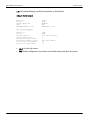
The next help screen (help3 command) contains configuration commands specific to translation tables:
Listing 10 - Tables related commands
>help3
Tables related commands
------ ------- ------->
TBLRST
Reset all tables to factory defaults
>
TBLVIEW:F
View the contents of a Translation Table
>
TBLDEL: F,P
Delete one row from a Translation Table
>
TBLINS: F,P,N
Insert one row into a Translation Table
=======================================
|Parameter|
Legal values
|
|=======================================|
www.exemys.com
Rev. 1.4.0
Page 15
SGW1-MB-DF1 User’s Manual
Advanced Topics
|
F
|
N
|
B
|
S
|
|=======================================|
|
P
| 0..K1+1 | 0..K2+1 |
not
|
|=============================| allowed |
|
| DF1
| DF1
|(S table |
|
N
| File
| File
|is fixed)|
|
| Number | Number |
|
|=======================================|
K1 is the last occupied position in the N table;
0<=K1<=30
K2 is the last occupied position in the B table;
K2=0
For next help screen, type HELP4. For previous help screen, type HELP2
>
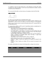
Note that this help screen is displayed as a chart. It contains details about how to perform
insertions and deletions. It also shows how to view and reset the contents of the tables.
TBLRST: This command resets the tables to factory defaults. Note that the S table will remain
unchanged, because it is fixed (not user configurable).
TBLVIEW: This one shows the contents of a table. If no parameter is appended, it shows the
contents of the four tables.
TBLDEL: Deletes a record in a table.
TBLINS: Inserts a row into a table. You can insert a record into an intermediate position by
selecting the appropriate row. After insertion, rows below the insertion point will be shifted
downwards.
Modbus address boundaries are assigned automatically by the device. For example, if you insert a
record into the first position of the N Table, the first Element is mapped to Holding Register
40192, the second Element is mapped to Holding Register 40193 and so on. Thus, you will have
to configure your Modbus master to make polls within those boundaries in order to obtain valid
answers.
3.4 General commands
The next help screen (help4 command) contains general configuration not covered in the
previous screens:
Listing 11 - General commands
>help4
General commands
-------- ------->
FACTRESET
>
LIST
>
HELP
>
END
End of help screen. For
Restores factory defaults
Show configuration values
Display the help screen
Finish configuration
previous help screen, type HELP3
>
FACTRESET: Resets the device to factory values (recovers default configuration, cleans the tables).
www.exemys.com
Rev. 1.4.0
Page 16
SGW1-MB-DF1 User’s Manual
Advanced Topics
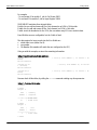
LIST: This command displays currently set parameters, as shown below:
Listing 12- The list command
>list
Baud rate:
Parity:
Modbus exceptions:
Mode:
Embedded Modbus Slave:
DF1 related commands
--- ------- -------Baud rate:
Parity:
Message Timeout:
Source address (SRC):
Destination address (DST):
Destination address option:
Error detection mechanism:
B files bit organization:
>
115200
NONE
ENABLED
RTU
ENABLED,ID = 240
19200
NONE
1000 [milliseconds]
0
1
Use fixed address
CRC
16
HELP: Lists the help screens.
END: Finishes configuration. Stores data in non-volatile memory and closes the console.
www.exemys.com
Rev. 1.4.0
Page 17
SGW1-MB-DF1 User’s Manual
The Embedded Modbus Slave
Chapter 4
Chapter
The Embedded Modbus Slave
This chapter explains how to take advantage of the embedded Modbus slave. Remote
inputs/outputs are made visible to the user through this Modbus service.
4.1 Enabling the slave
Refer to SLVCFG command in section 3.1 to enable the slave.
4.2 Monitoring and controlling built-in digital inputs and outputs
Input and output pins are located in the bottom connectors of the SGW1-MB-DF1 case.
The four digital inputs are mapped to Input Status locations, as shown in the following table:
Pin Number
Digital Input
Input Status
9
I0
10001
10
I1
10002
11
I2
10003
12
I3
10004
Recall that Input Status locations are read-only variables. After you issue a read input command,
the pins are read and the measure is reported through the answer.
The four digital outputs are mapped to Coil Status locations, as shown in the following table:
Pin Number
13
Digital Output O0
Coil Status
00001
14
O1
00002
15
O2
00003
16
O3
00004
Coil Status locations are read-write variables. Thus, both reads and writes are allowed for the I/O
pins.
www.exemys.com
Rev. 1.4.0
Page 18
SGW1-MB-DF1 User’s Manual
A.Cabling
Cabling
Appendix A
Appendix
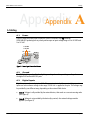
A.1.
Power
Figure 3 shows the power input connection, which is located in the Vin terminals.
SGW1-MB-DF1 powering has no polarity and accepts an input voltage range of 9 to 30 VDC and
9 to 26 VAC.
9-30 VDC
9-26 VAC
Vin
Vin
Figure 3 - Power Input Connection Scheme
A.2.
Ground
The GND pin (pin number 4) is the digital ground signal used to provide grounding reference to
the digital I/Os and both RS-232 ports.
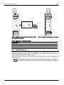
A.3.
Digital Inputs
Digital inputs are located at pins 9-12. They are terminated with current-sinking transistors.
Inputs are active when a voltage in the range 3.5-28 Vdc is applied to the pins. This voltage may
be provided by two different ways, depending on the external field device:
Case A: Voltage is self-provided by the external device, that works as a current-sourcing node.
(See Figure 4)
Case B: Voltage is not provided by the device (dry contact). An external voltage must be
applied. (See Figure 5)
www.exemys.com
Rev. 1.4.0
Page 19
SGW1-MB-DF1 User’s Manual
Cabling
9-30 VDC
9-26 VAC
Power Supply
9-30 VDC
9-26 VAC
Power Supply
+
+
Vin
Vin
2
1
5
6
GND
3
7
Vin
4
8
5
Field Device
(PLC, Sensor, Encoder, etc)
Power
GND
Vin
1
2
6
3
7
4
8
Power
+Vdc
L1
L1
COMMON
L2
OUTPUT Voltage
(3.5 a 28 VDC Max.)
(Sourcing)
L2
Power Supply
of the Device
SGW1
IØ
9
10
13
14
11
15
SGW1
12
9
10
11
12
IØ
16
13
Figure 4 - Digital Input connected to an external device with
an independent power supply
14
15
16
Figure 5 - Digital input connected to a dry contact
Table 2 - Digital Inputs - Technical Specifications
Digital Inputs
Inputs Type
Operating Voltage Range
Input Current
A.4.
Sinking. Allow dry contacts and current sourcing devices
3.5 - 28 Vdc
1 - 11 mA
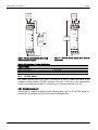
Digital Outputs
This device provides four digital outputs located at pins 13-16. Digital outputs are Open Collector.
This means that, when active, outputs are electrically tied to GND. Any load connected to an
output should be powered in the range 3 - 45 Vdc .
When connecting an output to an external load, two situations may occur. These situations are
covered below.
Case A: The external load and the Exemys device use different power supplies. (See Figure 6)
Case B: The external load and the Exemys device share the same power supply. (See Figure 7)
www.exemys.com
Rev. 1.4.0
Page 20
SGW1-MB-DF1 User’s Manual
Cabling
9-30 VDC
9-26 VAC
Power Supply
9-30 VDC
9-26 VAC
Power Supply
+
+
Vin
Vin
1
5
2
6
GND
3
Vin
5
8
7
Power
2
6
3
7
4
8
Power
+
3-45 VDC
Power
Supply
L1
GND
Vin
1
4
LOAD
Relay / Lamp,
etc.
L2
L1
L2
LOAD
Relay / Lamp,
etc.
SGW1
SGW1
9
13
10
14
11
15
9
12
13
16
10
14
11
15
12
16
OØ
OØ
Figure 7 - The load and the Exemys device share the
power supply
Figure 6 - The load and the Exemys device using
two different power supplies
Table 3 – Digital Outputs – Technical Specifications
Digital Outputs
Output Type
Maximum Load Voltage
Current
A.5.
Open Collector. Current Sinking
3 - 45 Vdc Max.
130mA Max. Per output
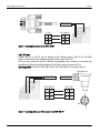
RS-232 Ports
This product provides two RS-232 ports. The first one is used to connect the device to the
computer (running Modbus ASCII/RTU protocol). This port is also tied to the command-line
console. The second port provides DF1 connectivity, so it is always connected to the PLC.
A.5.1. Modbus/console port
Connect your PC comport as depicted in the following figure. Only TX, RX and GND signals are
provided (do not configure any kind of flow control in the application).
www.exemys.com
Rev. 1.4.0
Page 21
SGW1-MB-DF1 User’s Manual
Cabling
5
3
2
4
PC COM
SGW1-MB-DF1
5
GND
GND
4
3
Tx
RxD
5
2
Rx
TxD
6
5 6
Figure 8 - Connecting the computer to the SGW1-MB-DF1
A.5.2. DF1 port
Connect the PLC to the DF1 port as depicted in the following figures. Only TX, RX and GND
signals are provided (do not configure any kind of flow control in the PLC).
Since you may connect this device to different Programmable Logic Controllers, we provide two
examples that illustrate the wiring diagram for this device and two commercial PLCs.
Micrologix 1000: Connect the Micrologix 1000 to the SGW1-MB-DF1 as shown in Figure 9
8-pin Mini Din
4
SGW1-MB-DF1
7 8
MLX 1000
4
GND
GND
2
7
Tx
Rx
4
8
Rx
Tx
7
7
4
2
Figure 9 - Connecting a Micrologix 1000 processor to the SGW1-MB-DF1
www.exemys.com
Rev. 1.4.0
Page 22
SGW1-MB-DF1 User’s Manual
Cabling
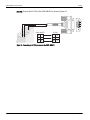
SLC 500: Connect the SLC 500 to the SGW1-MB-DF1 as shown in Figure 10
5
3
2
4
SGW1-MB-DF1
7 8
SLC500
4
GND
GND
5
7
Tx
RxD
2
8
Rx
TxD
3
Figure 10 - Connecting an SLC 500 processor to the SGW1-MB-DF1
www.exemys.com
Rev. 1.4.0
Page 23
SGW1-MB-DF1 User’s Manual
Monitoring the device through the built-in LEDs
Appendix B
Appendix
B.Monitoring the device through the built-in LEDs
The frontal LEDs provide status information about the device. The meaning of the blinking is
provided in the following table.
Table 4 - Meaning of the LEDs blinking
www.exemys.com
LED
Meaning
Green
Yellow
Modbus activity.
DF1 activity
Rev. 1.4.0
Page 24
SGW1-MB-DF1 User Manual
Configuring FlexLogix and ControlLogix PLCs
Appendix C
Appendix
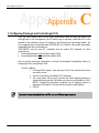
C.Configuring FlexLogix and ControlLogix PLCs
Time ago, Allen Bradley came out with some modifications about the way that newer PLCs
exchange data. In the new approach, the PLC defines tags to map data, rather than Files. At the
moment of this publication, those PLCs belong to the FlexLogix and ControlLogix families. The
new commands are not compatible with SGW1-MB-DF1, yet. However, AB provides downwardscompatibility with the old command set.
SGW1-MB-DF1 only uses two DF1 commands from the original DF1 command set. These
commands are:
Protected typed logical read with three address fields
Protected typed logical write with three address fields
Here we provide some basic information to activate the downward compatibility feature, by
configuring the PLC using RSLogix 5000.
To map an address:
1. In RSLogix 5000 software, open the project file for the controller whose data
you want to access
2. From the Logic menu, select Map PLC/SLC Messages
3. The screen shown will be used to provide the actual mapping between an
already defined tag and the File Number you choose to make public to SGW1MB-DF1. Complete the information required as an SLC mapping. (Choose an
appropriate File Number). The tags must be controller-scoped (global).
4. Click OK
If you want to map many data into one File, you can define a tag as an array.
NOTE
www.exemys.com
Rev. 1.4.0
Page 25