1
Acknowledgements
PCL is a Trademark of Hewlett-Packard Company.
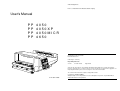
User's Manual
PP
PP
PP
PP
4050
4050XP
4050MICR
4650
A Publication of PSi Laser GmbH
Eiserfelder Straße 316
57080 Siegen @ Germany
http://www.psi-laser.de
Version:
5112 991 15506
August 2009
Great care has been taken to ensure that the information in this handbook is accurate and complete.
However, should any errors or omissions be discovered or should any user wish to make suggestions for
improving this handbook, please feel encouraged to send us the relevant details.
The contents of this manual are subject to change without notice.
5112 991 15506
Copyright © by PSi Laser GmbH.
All rights strictly reserved. Reproduction or issue to third parties in any form is not permitted without
written authorization from the publisher.
Safety Regulations
Safety Regulations for the Laser Printer PP 4x50 and
PP 4050XP and the intelligent Paper Stacker iPS 4050E
Electromagnetic Compatibility
We certify that the equipment at issue,
Type: Printer PP 4050, PP 4050MICR, PP 4050XP, PP 4650 and the
The LED printers PP 4050, PP 4050MICR, PP 4050XP, PP 4650 and the
intelligent Paper Stacker iPS 4050E fulfils the safety regulations according to
IEC, VDE/GS, and UL / C-UL for information technology equipments (EN 60950,
UL 1950 3rd Edition / CAN/CSA C22.2 No 950-95).
Note:
The commercial name of the iPS 4050E is iPS 4050/4060).
intelligent Paper Stacker iPS 4050E
corresponds to the laws and regulations ruling electromagnetic compatibility of
appliances (89/336/EWG) and, therefore, fulfils the requirements for conformity
marking with the CE-sign.
To guarantee that the device stays within the limits according to the approval
regulations for conducted and radiated emission (EN 55022, Class B) and
immunity (EN 55024) in any case shielded interface cables are to be used only.
The mains cable must be connected to a ground protected wall-socket. The
printer's voltage has to be in accordance with the local mains voltage.
Note:
The power plug must be easily accessible at any time so that it can be
disconnected immediately in case of danger or for maintenance purposes.
Before installing the printer, check the surrounding conditions in which the
printer is intended to be used (see next page, Operating Environment).
During thunderstorm you should never attempt to connect or disconnect any
data transfer cable.
The power supply should only be opened and checked by authorized personnel.
Maintenance beyond the descriptions of chapter 5 may only be attempted by
authorized personnel. Repairs done inappropriately may seriously jeopardize
the user's safety.
Attention:
This symbol is standing for a hot surface - danger
of burning!
This equipment has been tested and found to comply with the limits for a
CLASS A digital device pursuant to Part 15 of the FCC Rules. These
limits are designed to provide reasonable protection against harmful
interference when the equipment is operated in a commercial
environment. This equipment generates, uses, and can radiate radio
frequency energy and, if not installed and used in accordance with the
instruction manual, may cause harmful interference to radio
communications. Operation of this equipment in a residential area is
likely to cause harmful interference in wich case the user will be required
to correct the interference at his own expense.
Changes and modifications not explicitly allowed by the equipment's
manufacturer could void the user's authority to operate the equipment.
Operating Environment
Avoid installing the printer where it is exposed to moisture or heat (eg. direct
sunlight).
The printer is designed to operate in a wide range of environmental conditions.
S Temperature: + 15°C to + 35°C (+59°F to + 95°F)
S Humidity:
30% to 50%
For best performance, store and use fanfold paper at 19E to 23° C (68° to 73°F)
and a relative humidity of 33 to 47 percent.
Note:
I
II
In case of higher values for temperature and humidity the print quality
will degrade!
Safety Regulations
Safety Regulations
Power Requirements
S 100 - 110 V (-10/+6%) AC, 12 A (average)
S 100 - 110 V (-10/+6%) AC, 12 A (average)
S 110 - 120 V (-10/+6%) AC, 12 A (average)
S 220 - 240 V (-10/+6%) AC, 6 A (average)
S
50 - 60 Hz
Note:
Caution, the chain of the motor to move the paper exit tray
up and down will start automatically or after pushing the
key at the front side of the table.
To avoid an overload of the electric circuit support (particularly for 100 to
110 or 110 to 120V) connect the power supply plug of the printer into a
separate protected power wall socket.
Moving lift can crush.
Keep feet clear.
Power Consumption
S Operating power
S
S
Operating current
Power save
Notes:
See instructions manual.
< 1.200 Watt average; (<1.650 W peak during
Warming Up)
< 100 Watt
# 45 W
The feet of the laser printer PP 4050, PP 4050MICR, PP 4050XP or PP 4650
should be positioned into the depressions of the stacker's table.
Slots and openings in the printer's housing are provided for
ventilation. Always ensure that these openings are not obstructed.
Note:
Also ensure that the cables of the printer do not interfere with the
output paper path.
During the printing process ozone will be produced. Take care that
the printer is standing in a room with good ventilation. The limt of
ozone concentration should be 0,1 ppm (0,2 mg/m3). Note that the
specific gravity of ozone is higher than that of air.
Caution:
Danger of explosation if battery is incorrectly replaced!
Replace only with the same or equivalent type recommended by the
manufacturer. Dispose of used batteries according to the batteries
manufacturer´s instructions.
The intelligent Paper Stacker iPS 4050E can only be used in conjunction with
the printer PP 4050, PP 4050MICR, PP 405XP, PP 4060 or PP 4650.
Caution:
Caution, the paper exit tray moves up and down
automatically or after pushing the key at the front
side of the table. Keep your feet clear when the
paper exit tray moves down. Ensure that the cables
at the rear of the printer do not interfere with the
paper path within the stacker.
Connector not located in limited Power Source! Only for connecting
Paper Stacker (iPS 4050E). Refere to User´s Manual.
III
IV
Open windows, airing, and also draught disturb the paper flow!
Table of Contents
Table of Contents
1.8
Handling of the Tractor Cassettes . . . . . . . . . . . . . . . . . . . . . . . . 1-20
1.9
-
Inserting Fanfold Paper . . . . . . . . . . . . . . . . . . . . . . . . . . . . . . . . . 1-21
Inserting paper for the first time or changing to another paper width 1-22
Preface . . . . . . . . . . . . . . . . . . . . . . . . . . . . . . . . . . . . . . . . . . . . . . . . . . . . . XIII
About this Manual . . . . . . . . . . . . . . . . . . . . . . . . . . . . . . . . . . . . . . . . . . . . . XIII
Conventions Used in this Guide . . . . . . . . . . . . . . . . . . . . . . . . . . . . . . . . . . XIV
1.10 Operating the intelligent Paper Stacker (iPS) . . . . . . . . . . . . . . . 1-23
1.10.1 Adjusting the Paper Exit Tray . . . . . . . . . . . . . . . . . . . . . . . . . . . 1-23
1.10.2 Remove Paper . . . . . . . . . . . . . . . . . . . . . . . . . . . . . . . . . . . . . . 1-24
1. Installing the Printer and intelligent Paper Stacker . . . . . . . . . . . . . . 1-1
1.1
Requirements to the location of the printer . . . . . . . . . . . . . . . . . . 1-1
1.1.1 Environmental Conditions . . . . . . . . . . . . . . . . . . . . . . . . . . . . . . . 1-1
2. Printer Operation . . . . . . . . . . . . . . . . . . . . . . . . . . . . . . . . . . . . . . . . . .
2.1
Control Panel . . . . . . . . . . . . . . . . . . . . . . . . . . . . . . . . . . . . . . . . . .
2.1.1 Description of the two Indicators . . . . . . . . . . . . . . . . . . . . . . . . . .
2.1.2 Description of the Panel Display . . . . . . . . . . . . . . . . . . . . . . . . . .
2.1.3 Function Keys . . . . . . . . . . . . . . . . . . . . . . . . . . . . . . . . . . . . . . . .
1.2
A First Look at the Device . . . . . . . . . . . . . . . . . . . . . . . . . . . . . . . . 1-4
1.3
Installing the intelligent Paper Stacker . . . . . . . . . . . . . . . . . . . . . 1-5
1.3.1 Check delivery for Completeness . . . . . . . . . . . . . . . . . . . . . . . . . 1-5
1.4
Installing the Printer . . . . . . . . . . . . . . . . . . . . . . . . . . . . . . . . . . . . . 1-6
1.4.1 Check delivery for Completeness . . . . . . . . . . . . . . . . . . . . . . . . . 1-6
1.4.2 Put the Printer onto the intelligent Paper Stacker (iPS) . . . . . . . . 1-6
1.4.3 Interconnect the Printer and iPS 4050/4060 . . . . . . . . . . . . . . . . . 1-8
1.4.4 Mount the Pendulum of the iPS 4050/4060 . . . . . . . . . . . . . . . . . 1-9
1.4.5 Remove the Transport Locks . . . . . . . . . . . . . . . . . . . . . . . . . . . 1-11
1.5
1.6
1.7
Installation of the Consumables . . . . . . . . . . . . . . . . . . . . . . . . . .
1.5.1 Loading the Developer Unit . . . . . . . . . . . . . . . . . . . . . . . . . . . .
1.5.2 Loading the Toner . . . . . . . . . . . . . . . . . . . . . . . . . . . . . . . . . . . .
1.5.3 Inserting the Waste Toner Bottle . . . . . . . . . . . . . . . . . . . . . . . .
1.5.4 Inserting the Cleaner Felt . . . . . . . . . . . . . . . . . . . . . . . . . . . . . .
1.5.5 Inserting the Ozone Filter . . . . . . . . . . . . . . . . . . . . . . . . . . . . . .
1.5.6 Installing the PC Cartridge (OPC) . . . . . . . . . . . . . . . . . . . . . . . .
1-12
1-12
1-13
1-14
1-15
1-16
1-17
Connection to a Computer or to a Network . . . . . . . . . . . . . . . . . 1-18
1.6.1 PP 4050 Parallel Interface . . . . . . . . . . . . . . . . . . . . . . . . . . . . . 1-18
1.6.2 PP 4050XP / PP 4650 Parallel and Ethernet Interface . . . . . . . . 1-18
2.2
Menu Mode . . . . . . . . . . . . . . . . . . . . . . . . . . . . . . . . . . . . . . . . . . . . 2-7
2.2.1 To Activate the Menu . . . . . . . . . . . . . . . . . . . . . . . . . . . . . . . . . . 2-8
2.2.2 To Confirm and Save Selection . . . . . . . . . . . . . . . . . . . . . . . . . . 2-9
2.2.3 Example to Change the Language at the Control Panel . . . . . . 2-10
2.3
Status and Error Messages . . . . . . . . . . . . . . . . . . . . . . . . . . . . . . 2-11
3. Configuring the Printer . . . . . . . . . . . . . . . . . . . . . . . . . . . . . . . . . . . . .
3.1
What is Configuring? . . . . . . . . . . . . . . . . . . . . . . . . . . . . . . . . . . . .
3.1.1 Profiles . . . . . . . . . . . . . . . . . . . . . . . . . . . . . . . . . . . . . . . . . . . . .
S Profiler 4050 and Profiler 4050/4060 . . . . . . . . . . . . . . . . . . . . . .
3.1.2 Basic Printer Settings . . . . . . . . . . . . . . . . . . . . . . . . . . . . . . . . . .
3.1.3 Test Mode . . . . . . . . . . . . . . . . . . . . . . . . . . . . . . . . . . . . . . . . . . .
3-1
3-1
3-1
3-2
3-2
3-2
3.2
Printout of Standard Configuration . . . . . . . . . . . . . . . . . . . . . . . . 3-3
3.2.1 How to Start the SELF TEST . . . . . . . . . . . . . . . . . . . . . . . . . . . . 3-4
3.3
Printout of the Profiles . . . . . . . . . . . . . . . . . . . . . . . . . . . . . . . . . . . 3-6
3.4
Menu Structure . . . . . . . . . . . . . . . . . . . . . . . . . . . . . . . . . . . . . . . . . 3-7
Power ON/OFF Switch . . . . . . . . . . . . . . . . . . . . . . . . . . . . . . . . . . 1-19
V
2-1
2-1
2-1
2-2
2-6
VI
Table of Contents
3.5
S
S
S
S
S
S
S
S
S
S
Menu Mode Item Description . . . . . . . . . . . . . . . . . . . . . . . . . . . . . . 3-9
OFFLINE Mode . . . . . . . . . . . . . . . . . . . . . . . . . . . . . . . . . . . . . . . . . 3-9
Select Profile . . . . . . . . . . . . . . . . . . . . . . . . . . . . . . . . . . . . . . . . . . . 3-9
Paper Menu . . . . . . . . . . . . . . . . . . . . . . . . . . . . . . . . . . . . . . . . . . . 3-10
PCL Menu . . . . . . . . . . . . . . . . . . . . . . . . . . . . . . . . . . . . . . . . . . . . . 3-12
Hexdump Menu . . . . . . . . . . . . . . . . . . . . . . . . . . . . . . . . . . . . . . . . 3-13
General Menu . . . . . . . . . . . . . . . . . . . . . . . . . . . . . . . . . . . . . . . . . . 3-14
Config Menu . . . . . . . . . . . . . . . . . . . . . . . . . . . . . . . . . . . . . . . . . . . 3-15
Clock Menu (only PP 4050XP/PP 4650) . . . . . . . . . . . . . . . . . . . . . 3-16
Test Menu . . . . . . . . . . . . . . . . . . . . . . . . . . . . . . . . . . . . . . . . . . . . . 3-16
Info Menu . . . . . . . . . . . . . . . . . . . . . . . . . . . . . . . . . . . . . . . . . . . . . 3-17
S
S
Configuration Programs . . . . . . . . . . . . . . . . . . . . . . . . . . . . . . . . 3-18
Profiler . . . . . . . . . . . . . . . . . . . . . . . . . . . . . . . . . . . . . . . . . . . . . . . 3-18
InterCon-NetTool . . . . . . . . . . . . . . . . . . . . . . . . . . . . . . . . . . . . . . . 3-18
3.6
Table of Contents
S
4.2.2 PCL MENU . . . . . . . . . . . . . . . . . . . . . . . . . . . . . . . . . . . . . . . . .
S FONT NUMBER . . . . . . . . . . . . . . . . . . . . . . . . . . . . . . . . . .
S PITCH . . . . . . . . . . . . . . . . . . . . . . . . . . . . . . . . . . . . . . . . . .
S POINT SIZE . . . . . . . . . . . . . . . . . . . . . . . . . . . . . . . . . . . . .
S SYMBOL SET . . . . . . . . . . . . . . . . . . . . . . . . . . . . . . . . . . . .
S LINE SPACING . . . . . . . . . . . . . . . . . . . . . . . . . . . . . . . . . . .
S TOP MARGIN . . . . . . . . . . . . . . . . . . . . . . . . . . . . . . . . . . . .
S LEFT MARGIN . . . . . . . . . . . . . . . . . . . . . . . . . . . . . . . . . . .
S RIGHT MARGIN . . . . . . . . . . . . . . . . . . . . . . . . . . . . . . . . . .
S TEXT LENGTH . . . . . . . . . . . . . . . . . . . . . . . . . . . . . . . . . . .
S PERF. SKIP . . . . . . . . . . . . . . . . . . . . . . . . . . . . . . . . . . . . .
S $$ COMMANDS . . . . . . . . . . . . . . . . . . . . . . . . . . . . . . . . . .
Menu Mode CHANGE PROFILE . . . . . . . . . . . . . . . . . . . . . . . . . . . . 4-3
4.2.1 PAPER MENU . . . . . . . . . . . . . . . . . . . . . . . . . . . . . . . . . . . . . . . 4-3
S PAPER . . . . . . . . . . . . . . . . . . . . . . . . . . . . . . . . . . . . . . . . . . 4-3
S PAPER LENGTH . . . . . . . . . . . . . . . . . . . . . . . . . . . . . . . . . . . 4-4
S LENGTH FACTOR . . . . . . . . . . . . . . . . . . . . . . . . . . . . . . . . . 4-4
S IMAGE WIDTH . . . . . . . . . . . . . . . . . . . . . . . . . . . . . . . . . . . . 4-5
S SOURCE . . . . . . . . . . . . . . . . . . . . . . . . . . . . . . . . . . . . . . . . . 4-5
S DESTINATION . . . . . . . . . . . . . . . . . . . . . . . . . . . . . . . . . . . . 4-5
S ORIENTATION . . . . . . . . . . . . . . . . . . . . . . . . . . . . . . . . . . . . 4-6
S LANDSCAPE MODE . . . . . . . . . . . . . . . . . . . . . . . . . . . . . . . . 4-7
S ORIENT. MODE . . . . . . . . . . . . . . . . . . . . . . . . . . . . . . . . . . . 4-8
S PAPER EXTENDED . . . . . . . . . . . . . . . . . . . . . . . . . . . . . . . . 4-9
S PAPER SELECTION . . . . . . . . . . . . . . . . . . . . . . . . . . . . . . . . 4-9
S PAPER PATH SELECT. . . . . . . . . . . . . . . . . . . . . . . . . . . . . . 4-9
S FUSER TEMP. . . . . . . . . . . . . . . . . . . . . . . . . . . . . . . . . . . . 4-10
S TONER DENSITY . . . . . . . . . . . . . . . . . . . . . . . . . . . . . . . . . 4-10
S VER SHIFT . . . . . . . . . . . . . . . . . . . . . . . . . . . . . . . . . . . . . . 4-10
S HOR SHIFT . . . . . . . . . . . . . . . . . . . . . . . . . . . . . . . . . . . . . . 4-10
S CUT SHIFT . . . . . . . . . . . . . . . . . . . . . . . . . . . . . . . . . . . . . . 4-10
VII
4-12
4-12
4-12
4-12
4-13
4-14
4-14
4-14
4-14
4-14
4-14
4-15
4.2.3 HEXDUMP MENU . . . . . . . . . . . . . . . . . . . . . . . . . . . . . . . . . . . 4-15
S UEL COMMAND . . . . . . . . . . . . . . . . . . . . . . . . . . . . . . . . . . 4-15
4 Explanation of Individual Menu Items . . . . . . . . . . . . . . . . . . . . . . . . . 4-1
4.1
Menu Mode SELECT PROFILE . . . . . . . . . . . . . . . . . . . . . . . . . . . . . 4-3
4.2
INT. LINE REGISTR. . . . . . . . . . . . . . . . . . . . . . . . . . . . . . . . 4-11
4.3
VIII
4.2.4 GENERAL MENU . . . . . . . . . . . . . . . . . . . . . . . . . . . . . . . . . . . .
S EMULATION . . . . . . . . . . . . . . . . . . . . . . . . . . . . . . . . . . . . .
S AUTO FORM FEED . . . . . . . . . . . . . . . . . . . . . . . . . . . . . . .
S AUTOMATIC CUT . . . . . . . . . . . . . . . . . . . . . . . . . . . . . . . . .
S JOB SEPARATION . . . . . . . . . . . . . . . . . . . . . . . . . . . . . . . .
S TRACTOR CHANGE CUT . . . . . . . . . . . . . . . . . . . . . . . . . .
S REPRINT LAST PAGE . . . . . . . . . . . . . . . . . . . . . . . . . . . . .
4-16
4-16
4-16
4-16
4-17
4-17
4-18
Menu Mode BASIC SETTINGS . . . . . . . . . . . . . . . . . . . . . . . . . . . .
4.3.1 CONFIG. MENU . . . . . . . . . . . . . . . . . . . . . . . . . . . . . . . . . . . . .
S POWER SAVE . . . . . . . . . . . . . . . . . . . . . . . . . . . . . . . . . . .
S KEEP TEMP. HIGH . . . . . . . . . . . . . . . . . . . . . . . . . . . . . . . .
S ALARM BELL . . . . . . . . . . . . . . . . . . . . . . . . . . . . . . . . . . . .
S LANGUAGE . . . . . . . . . . . . . . . . . . . . . . . . . . . . . . . . . . . . .
S MENU ACCESSS . . . . . . . . . . . . . . . . . . . . . . . . . . . . . . . . .
S HOST CHANNEL . . . . . . . . . . . . . . . . . . . . . . . . . . . . . . . . .
S TRACTOR POOL . . . . . . . . . . . . . . . . . . . . . . . . . . . . . . . . .
S CMC7 Bar Width . . . . . . . . . . . . . . . . . . . . . . . . . . . . . . . . . .
S RECALL FACTORY . . . . . . . . . . . . . . . . . . . . . . . . . . . . . . .
S RESET DEVELOPER INFO . . . . . . . . . . . . . . . . . . . . . . . . .
4-19
4-19
4-19
4-19
4-20
4-20
4-20
4-21
4-21
4-21
4-21
4-23
Table of Contents
S
S
Table of Contents
RESET OPC INFO. . . . . . . . . . . . . . . . . . . . . . . . . . . . . . . . . 4-23
RESET FUSER INFO . . . . . . . . . . . . . . . . . . . . . . . . . . . . . . 4-23
5.3
Installing the Parts of the Fuser Kit . . . . . . . . . . . . . . . . . . . . . . . 5-12
5.3.1 Replacing the Fuser Unit . . . . . . . . . . . . . . . . . . . . . . . . . . . . . . 5-13
4.3.2 Clock Menu . . . . . . . . . . . . . . . . . . . . . . . . . . . . . . . . . . . . . . . . . . . . 4-23
5.4
Replacement of the PC Cartridge (OPC) . . . . . . . . . . . . . . . . . . . . . 5-14
4.4
5.5
Menu Mode TEST MODE . . . . . . . . . . . . . . . . . . . . . . . . . . . . . . . . .
4.4.1 TEST MENU . . . . . . . . . . . . . . . . . . . . . . . . . . . . . . . . . . . . . . . .
S PANEL TEST . . . . . . . . . . . . . . . . . . . . . . . . . . . . . . . . . . . .
S SELF TEST . . . . . . . . . . . . . . . . . . . . . . . . . . . . . . . . . . . . . .
S CONT SELF TEST . . . . . . . . . . . . . . . . . . . . . . . . . . . . . . . .
S CONFIG. PRINT . . . . . . . . . . . . . . . . . . . . . . . . . . . . . . . . . .
S PCL TYPEFACE LIST . . . . . . . . . . . . . . . . . . . . . . . . . . . . . .
4-24
4-24
4-24
4-24
4-24
4-24
4-25
4.4.2 INFO MENU . . . . . . . . . . . . . . . . . . . . . . . . . . . . . . . . . . . . . . . .
S ENGINE ID . . . . . . . . . . . . . . . . . . . . . . . . . . . . . . . . . . . . . .
S FIRMWARE VERSION . . . . . . . . . . . . . . . . . . . . . . . . . . . . .
S STACKER VERSION . . . . . . . . . . . . . . . . . . . . . . . . . . . . . .
S PANEL VERSION . . . . . . . . . . . . . . . . . . . . . . . . . . . . . . . . .
S DEVELOPER INFO . . . . . . . . . . . . . . . . . . . . . . . . . . . . . . . .
S OPC INFO . . . . . . . . . . . . . . . . . . . . . . . . . . . . . . . . . . . . . . .
S FUSER INFO . . . . . . . . . . . . . . . . . . . . . . . . . . . . . . . . . . . . .
4-27
4-27
4-27
4-27
4-27
4-27
4-27
4-27
5 Maintenance . . . . . . . . . . . . . . . . . . . . . . . . . . . . . . . . . . . . . . . . . . . . . .
5.1
Installing the Parts of the Toner Kit . . . . . . . . . . . . . . . . . . . . . . . .
5.1.1 Refilling the Toner . . . . . . . . . . . . . . . . . . . . . . . . . . . . . . . . . . . . .
5.1.2 Replacing the Waste Toner Bottle . . . . . . . . . . . . . . . . . . . . . . . .
5.1.3 Changing the Cleaner Felt . . . . . . . . . . . . . . . . . . . . . . . . . . . . . .
5.1.4 Replacing the Ozone Filter . . . . . . . . . . . . . . . . . . . . . . . . . . . . . .
5.2
5-1
5-1
5-2
5-4
5-5
5-7
Installing the Parts of the Developer Kit . . . . . . . . . . . . . . . . . . . . . 5-8
5.2.1 Replacing the Developer Unit . . . . . . . . . . . . . . . . . . . . . . . . . . . . 5-8
5.2.2 Replacing the Transfer Charger Unit . . . . . . . . . . . . . . . . . . . . . 5-10
5.2.3 Replacing the Ozone Filter . . . . . . . . . . . . . . . . . . . . . . . . . . . . . 5-11
IX
User Preventive Maintenance . . . . . . . . . . . . . . . . . . . . . . . . . . . .
5.5.1 Cleaning the Paper Path . . . . . . . . . . . . . . . . . . . . . . . . . . . . . . .
5.5.2 Cleaning the Transfer Charger Unit . . . . . . . . . . . . . . . . . . . . . .
5.5.3 Cleaning the Ozone Filter below the Transfer Charger . . . . . . .
5.5.4 Cleaning the Ozone Filter in the Top Cover . . . . . . . . . . . . . . . .
5.5.5 Tools for Cleaning . . . . . . . . . . . . . . . . . . . . . . . . . . . . . . . . . . . .
5.5.6 Cleaning the Corona Wire . . . . . . . . . . . . . . . . . . . . . . . . . . . . .
5.5.7 Cleaning the TPS Sensor . . . . . . . . . . . . . . . . . . . . . . . . . . . . . .
5-16
5-16
5-18
5-19
5-20
5-21
5-22
5-24
6
Trouble Shooting and Diagnostics . . . . . . . . . . . . . . . . . . . . . . . . . . . .
- How to Use this Section . . . . . . . . . . . . . . . . . . . . . . . . . . . . . . . . . . .
6.1
Power-related Problems . . . . . . . . . . . . . . . . . . . . . . . . . . . . . . . . .
6.2
Status and Error Messages . . . . . . . . . . . . . . . . . . . . . . . . . . . . . . .
6-1
6-1
6-2
6-2
7 Technical Data . . . . . . . . . . . . . . . . . . . . . . . . . . . . . . . . . . . . . . . . . . . .
7.1
Printer Specification . . . . . . . . . . . . . . . . . . . . . . . . . . . . . . . . . . . .
7.2
Connectivity . . . . . . . . . . . . . . . . . . . . . . . . . . . . . . . . . . . . . . . . . . .
7.3
Paper Handling . . . . . . . . . . . . . . . . . . . . . . . . . . . . . . . . . . . . . . . . .
7.3.1 Fanfold Paper . . . . . . . . . . . . . . . . . . . . . . . . . . . . . . . . . . . . . . . .
7.4
Control Unit . . . . . . . . . . . . . . . . . . . . . . . . . . . . . . . . . . . . . . . . . . . .
7.5
Consumables . . . . . . . . . . . . . . . . . . . . . . . . . . . . . . . . . . . . . . . . . .
7.6
Options . . . . . . . . . . . . . . . . . . . . . . . . . . . . . . . . . . . . . . . . . . . . . . .
7-1
7-1
7-3
7-3
7-4
7-4
7-4
7-4
8 Paper Specification . . . . . . . . . . . . . . . . . . . . . . . . . . . . . . . . . . . . . . . .
8.1
Basic Theory of Operation . . . . . . . . . . . . . . . . . . . . . . . . . . . . . . . .
8.2
Storing Media . . . . . . . . . . . . . . . . . . . . . . . . . . . . . . . . . . . . . . . . . .
8.3
Environmental Considerations . . . . . . . . . . . . . . . . . . . . . . . . . . . .
8.4
Guidelines and Specification for Selected Fanfold Paper . . . . . .
8.4.1 General Guidelines . . . . . . . . . . . . . . . . . . . . . . . . . . . . . . . . . . . .
S Quality . . . . . . . . . . . . . . . . . . . . . . . . . . . . . . . . . . . . . . . . . . . . . .
S Basic weight . . . . . . . . . . . . . . . . . . . . . . . . . . . . . . . . . . . . . . . . .
S Transport holes . . . . . . . . . . . . . . . . . . . . . . . . . . . . . . . . . . . . . . .
S Perforation . . . . . . . . . . . . . . . . . . . . . . . . . . . . . . . . . . . . . . . . . .
8-1
8-1
8-1
8-2
8-2
8-3
8-3
8-3
8-4
8-5
X
A-3.6 Macro Control Commands . . . . . . . . . . . . . . . . . . . . . . . . . . A-23
A-3.7 Graphic Commands . . . . . . . . . . . . . . . . . . . . . . . . . . . . . . . A-24
A-3.8 Status Readback Commands . . . . . . . . . . . . . . . . . . . . . . . . A-25
Table of Contents
8.4.2
8.4.3
8.4.4
8.4.5
9
Typical Paper Properties for Laser Printer . . . . . . . . . . . . . . . . . . 8-6
Paper / Form Properties . . . . . . . . . . . . . . . . . . . . . . . . . . . . . . . . 8-7
Label Carrier Properties . . . . . . . . . . . . . . . . . . . . . . . . . . . . . . . . 8-9
Label Properties . . . . . . . . . . . . . . . . . . . . . . . . . . . . . . . . . . . . . 8-10
Maintenance / Logbook . . . . . . . . . . . . . . . . . . . . . . . . . . . . . . . . . . . . .
9.1
Toner Kit . . . . . . . . . . . . . . . . . . . . . . . . . . . . . . . . . . . . . . . . . . . .
9.2
PC-Cartridge (OPC) . . . . . . . . . . . . . . . . . . . . . . . . . . . . . . . . . . .
9.3
Developer Kit . . . . . . . . . . . . . . . . . . . . . . . . . . . . . . . . . . . . . . . .
9.4
Fuser Kit . . . . . . . . . . . . . . . . . . . . . . . . . . . . . . . . . . . . . . . . . . . .
9.5
Inspection Report . . . . . . . . . . . . . . . . . . . . . . . . . . . . . . . . . . . . .
9.6
Customer Remarks . . . . . . . . . . . . . . . . . . . . . . . . . . . . . . . . . . . .
9-1
9-1
9-3
9-4
9-5
9-6
9-7
Programming Guide . . . . . . . . . . . . . . . . . . . . . . . . . . . . . . .
A-1
Support of Printer Specific Feature and Functions . . . . . . . . .
S A-1.1 Profiles . . . . . . . . . . . . . . . . . . . . . . . . . . . . . . . . . . . . . . . . . .
S A-1.2 Paper Size Select . . . . . . . . . . . . . . . . . . . . . . . . . . . . . . . . . .
S A-1.3 Paper Path Control . . . . . . . . . . . . . . . . . . . . . . . . . . . . . . . . .
S A-1.4 Semigraphics Support under SAP R/3 . . . . . . . . . . . . . . . . . .
A-1.5 EURO Symbol Support . . . . . . . . . . . . . . . . . . . . . . . . . . . . . .
A-1.6 Support of Logical and Physical Pages . . . . . . . . . . . . . . . . . .
A-1.7 Support of Job Separation . . . . . . . . . . . . . . . . . . . . . . . . . . .
A-1.8 Conventions . . . . . . . . . . . . . . . . . . . . . . . . . . . . . . . . . . . . . .
A-1
A-2
A-2
A-2
A-3
A-3
A-3
A-4
A-5
A-6
Appendix A
A-2
List of Supported PJL Control Functions . . . . . . . . . . . . . . . . . A-7
A-2.1 Basic Rules for PJL Programming . . . . . . . . . . . . . . . . . . . . . A-7
A-2.1.1 PJL Sytax Rules . . . . . . . . . . . . . . . . . . . . . . . . . . . . . . A-7
A-2.1.2 PJL Environments . . . . . . . . . . . . . . . . . . . . . . . . . . . . A-8
A-2.1.3 List of supported PJL Commands . . . . . . . . . . . . . . . . A-9
A-2.1.4 List of supported PJL Variables and Values . . . . . . . A-12
A-2.1.5 List of supported PJL Variables and Values
for PCL Personality . . . . . . . . . . . . . . . . . . . . . . . . . . A-15
A-3
List of supported PCL5 Control Functions . . . . . . . . . . . . . . .
A-3.1 Job Control Commands . . . . . . . . . . . . . . . . . . . . . . . . . . . .
A-3.2 Page Control Commands . . . . . . . . . . . . . . . . . . . . . . . . . . .
A-3.3 Cursor Positions Commands . . . . . . . . . . . . . . . . . . . . . . . .
A-3.4 Font Selection Commands . . . . . . . . . . . . . . . . . . . . . . . . . .
A-3.5 Font Management Commands . . . . . . . . . . . . . . . . . . . . . . .
A-4
A-5
Bar Code Programming . . . . . . . . . . . . . . . . . . . . . . . . . . . . . .
A-5.1 Resident Bar Code Font Code 39 HP Compatible . . . . . . . .
A-5.2 Resident Bar Code Controlled by
Private Command Sequence . . . . . . . . . . . . . . . . . . . . . . . .
A-5.2.1 Programming . . . . . . . . . . . . . . . . . . . . . . . . . . . . . . .
S Bar code print position . . . . . . . . . . . . . . . . . . . . . . . . . . .
S Bar code print orientation . . . . . . . . . . . . . . . . . . . . . . . .
S Bar code type . . . . . . . . . . . . . . . . . . . . . . . . . . . . . . . . .
S Bar code hight . . . . . . . . . . . . . . . . . . . . . . . . . . . . . . . . .
S Bar code data . . . . . . . . . . . . . . . . . . . . . . . . . . . . . . . . .
S Bar code text control . . . . . . . . . . . . . . . . . . . . . . . . . . . .
S Bar code module width . . . . . . . . . . . . . . . . . . . . . . . . . .
S Bar code ratio . . . . . . . . . . . . . . . . . . . . . . . . . . . . . . . . .
S Start and Stop characters . . . . . . . . . . . . . . . . . . . . . . . .
S Error checking characters . . . . . . . . . . . . . . . . . . . . . . . .
S Unprinted areas . . . . . . . . . . . . . . . . . . . . . . . . . . . . . . . .
A-5.3
S
S
S
S
S
S
S
S
S
S
S
Appendix B
A-16
A-16
A-17
A-19
A-21
A-22
XI
Support for Semigraphics for SAP/R3 . . . . . . . . . . . . . . . . . . A-26
XII
Bar Code Programming Examples . . . . . . . . . . . . . . . . . . . .
Code 39 . . . . . . . . . . . . . . . . . . . . . . . . . . . . . . . . . . . . . . . .
2 of 5 industrial . . . . . . . . . . . . . . . . . . . . . . . . . . . . . . . . . . .
2 of 5 interleaved . . . . . . . . . . . . . . . . . . . . . . . . . . . . . . . . .
EAN 8 SC2 . . . . . . . . . . . . . . . . . . . . . . . . . . . . . . . . . . . . . .
EAN 8 SC6 add 2 . . . . . . . . . . . . . . . . . . . . . . . . . . . . . . . . .
EAN 8 SC9 add 5 . . . . . . . . . . . . . . . . . . . . . . . . . . . . . . . . .
EAN 13 SC2 . . . . . . . . . . . . . . . . . . . . . . . . . . . . . . . . . . . . .
Codabar . . . . . . . . . . . . . . . . . . . . . . . . . . . . . . . . . . . . . . . .
Code 128 . . . . . . . . . . . . . . . . . . . . . . . . . . . . . . . . . . . . . . .
Postnet . . . . . . . . . . . . . . . . . . . . . . . . . . . . . . . . . . . . . . . . .
RMS4SCC / KIX . . . . . . . . . . . . . . . . . . . . . . . . . . . . . . . . . .
A-27
A-27
A-28
A-29
A-29
A-29
A-30
A-31
A-31
A-32
A-32
A-33
A-34
A-34
A-34
A-35
A-35
A-35
A-36
A-36
A-37
A-38
A-39
A-39
A-40
A-41
A-41
Symbol Sets . . . . . . . . . . . . . . . . . . . . . . . . . . . . . . . . . . . . . . B-1
Preface
Preface
Preface
4. Explanation of Individual Menu Items
In this chapter are the individual menu items are explained in detail.
About this Manual
This manual covers the printer in combination with the interface module, the
Personality Module. The Personality Module (PM) is an integral part of the
printer which determines the functionality of the printer especially regarding the
user and system interface.
The structure of this manual is such that the operator is led step-by-step through
the various procedures. Starting with unpacking and installation of the
consumables it moves on to setting-up configuration parameters and ends with
the mounting of options.
The manual is divided into the following chapters:
1. Installing the Printer and intelligent Paper Stacker
This chapter covers the information about the basic elements of the printer.
The next steps show how to power on the printer, the handling of the tractor
cassettes, inserting fanfold paper, and how to operate the intelligent Paper
Stacker (iPS 4050).
5. Maintenance
This chapter explains how to replace the consumables and maintain the
printer.
6. Trouble Shooting and Diagnostics
suggests how to identify and correct simple problems.
7. Technical Data
All technical details or data about the printer can be found here.
8. Paper Specification
Guidelines, Specification, Paper and Label properties are defined in this
chapter.
9. Maintenance / Logbook
All activities of maintenance should be written down here.
2. Operating the Printer
This chapter discusses in great detail the operation of the control panel, all
menu functions, and the general operation of the menu. General status
messages are also described.
3. Configuring the Printer
This chapter explains how to use the Profiles and to configure the printer so
that it can communicate with the corresponding system environment.
Furtheron this chapter includes a view of the Menu Structure and thoroughly
describes in a short form the printer's operating controls. Finally you will find
a description of the Configuration Programs Profiler 4050 and Profile
Selector 4050. The Profiler 4050 is a menu controlled program and
supported the printer configuration via PC. Different configurations can be
downloaded into the printer.
Profile Selector 4050 is a program for quick access to a profile.
XIII
XIV
Preface
Programming Guide
This appendix describes command extension of PCL5 and PJL in section 2
and 3. Bar Code Programming is described in section 5.
Appendix A
Symbol Sets
All supported Symbol Sets are listed.
Appendix B
Safe Energy
The PP 4x50 printer models have a special feature to save power. After a
specified period of inactivity, the printer changes to a low power state. When a
print job is received, the printer resumes the operating mode. This function is
changeable in the Configuration Menu with the item POWER SAVE. Standard
setting is 15 minutes.
Conventions Used in this Guide
The following conventions are used:
Miscellaneous
Order Numbers
Printer Driver
Appendix C
S
S
Preface
Bold
Headlines and important information.
Note:
Contains special advice to facilitate handling.
Caution:
Contains important information to prevent damage
of the equipment.
[ENTER]
Key functions are always depicted in brackets or
indicated by the corresponding symbol e.g.
.
The use of LEFT and RIGHT always assumes you are viewing the front i.e. the
control panel of the printer. For instance, the paper input is at the LEFT side of
the printer.
XV
XVI
16614
Installing the Printer and intelligent Paper Stacker
1.1
Installing the Printer and the intelligent Paper Stacker
S
Air circulation
In general there are no restrictions concerning air circulation. However, it is
to be observed that the air flow does not move the fanfold paper heavily at
the paper entry and paper exit of the printer and such may lead to paper
jams.
In conjunction with the paper stacking system care has to be taken that the
air flow does not disturb a proper operation of the stacker.
S
Impact of Light and Sunshine
Since the printer is equipped with a light-sensitive photoconductor drum and
optical sensors it shall in generally not be installed at a location which is
exposed to sunlight. If not otherwise possible window shades have to
provide for the necessary protection.
Requirements to the location of the printer
In this chapter the preconditions are described concerning the environment, the
physical prerequisites, and the demand for space which are required for
installation of the printer.
1.1.1 Environmental conditions
S Temperature and Humidity
The following table shows the values of temperature and relative humidity
which are specified for the printer and its consumables.
Note:
Temperature
Relative Humidity
Print operation *
Optimum range
+ 19 to + 23°C
+ 68 to + 73°F
33 to 47%
Print operation
Extended range
+ 15 to + 35°C
+ 56.5 to + 86°F
30 bis 50%
Transport and Storage
of the printer
- 10 to + 40°C
- 4 to + 104°F
max. 95%
(at + 40°C or + 104°F)
Transport and Storage
of the consumables **
- 10 to + 40°C
- 4 to + 104°F
max. 95%
(at 40°C or 104°F)
Storage of fanfold
paper
+ 19 to + 23°C
+ 68 to + 73°F
33 to 47%
*
If the top cover is opened to clear a paper jam or to perform maintenance
actions sunbeams would directly fall onto the photoconductor drum and
would permanently destroy its surface after an impact period of about 1
minute.
The photoeletrical process in a laser printer is influenced by the climatic
conditions of the environment. The herewith specified values define a
climate in which an optimal print quality is ensured. Operating the printer
outside this range may lead to a reduction of the print quality.
** It is recommended to store the consumables at a cool and dark location.
S
The printer must never be installed such that its right side (paper
exit) points to a window.
Altitude
The printer can be used at an altitude up to 2,135 m (7,000 ft.).
1-1
S
Acoustical Noise
The upper limits of the acoustical noise are shown below.
S Print Operation < 55 dB(A)
S Stand-by
< 48 dB(A)
S
Power Dissipation
If an interruption of a print operation occurs the printer can enter the Power
Save mode when for a certain period of time whose duration is selected at
the operator panel the printer does not perform any further operation. In this
mode most of the printer´s subsystems are disconnected from power. The
operating mode is resumed when the printer receives further data from the
host system.
Mode
Power Consumption
Operating
< 1,200 Watt average
< 1,650 Watt max.
Stand-by
< 100 Watt
Sleep Mode (Power Save)
< 45 Watt
1-2
Installing the Printer and the intelligent Paper Stacker
S
S
S
Weight and Dimensions
The printer´s weight is 112 kg (247 lbs.) with all consumables included.
The printer and the optional intelligent paper stacker both together weigh
164 kg (361 lbs.).
Printer incl. Stacker System
Width
810 mm; 32.9 inch
1.040 mm;
40.9 inch
Height
350 mm; 13.8 inch
1.140 mm;
44.9 inch
Depth
780 mm; 30.7 inch
780 mm;
30.7 inch
1
3
5
7
9
11
13
15
Accessability
To facilitate the handling of the printer (and the stacking system) by the
operator the below mentioned distances around the printer should be met
minimally:
S
S
S
S
Note:
S
1.2
Dimensions
Printer
Front
Rear
Left
Right
Installing the Printer and the intelligent Paper Stacker
A First Look at the devices
Laser Printer
Paper Exit for Cut Sheets
Paper Exit for Fanfold Paper
Control Panel
Upper Tractor
Pendulum
Shelf for Lower Tractor
Castors
2
4
6
8
10
12
14
Rear Cover
Top Cover
Front Cover
Lower Tractor
intelligent Paper Stacker (iPS)
Paper Exit Tray
Shelf for Upper Tractor
Note:
The intelligent Paper Stacker (10) - also called iPS 4050/4060 - is an
option!
Note:
The Printer drivers for Windows ® are available - see Appendix C Order
Numbers.
700 mm / 27.6 inch
140 mm / 5.5 inch
480 mm / 18.9 inch
400 mm / 15.8 inch
The intelligent paper stacker is equipped with castors which allow to
move the entire configuration to an empty space in case of maintenance
activities.
Preconditions for Installation
Floors and doors must be wide enough that the printer can pass them;
corners and angles must be large enough such that the printer can be
turned if necessary. For example a door must be 80 cm (31.5 inch) wide
minimally.
Elevators must be able to carry the printer and the personnel who transport
it. Doors of the elevators must be wide enough that the printer can pass
them.
It must be ensured that the floor space where the printer is to be installed
does not exceed the following horizontal inclinations:
S
S
from the front to the rear
from the left to the right
+ 1E
+ 2E
It must be safeguarded that an approved mains voltage wall socket is
available which provides for correct and sufficient current; the mains cord
must extend to the wall socket.
1-3
1-4
Installing the Printer and the intelligent Paper Stacker
1.3
Installing the Printer and the intelligent Paper Stacker
Installing the intelligent Paper Stacker
1.3.1 Check delivery for completeness
When unpacking, check contents of delivery by item against the list detailed
below. Contact your delivery agent immediately if any item is missing or
damaged.
S
The interface connector and protective
ground cable are packed into a
plastic bag (1).
The iPS 4050/4060 package should contain the following:
S iPS 4050/4060 basic unit (1)
S Pendulum (2)
S a box with the left and right Paper Guide (3)
S four Castors
1.4
Installing the Printer
1.4.1 Check delivery for completeness
When unpacking, check contents of delivery by item against the list detailed
below. Contact your delivery agent immediately if any item is missing or
damaged
The Starter Kit package should contain the following:
S 1 x Developer Unit incl. Toner Cartridge
S 2 x Tractor Cassettes
S 1 x PC-Cartridge
S 1 x Cleaner Felt
S 1 x Ozone Filter
S 1 x Toner Cartridge
S 1 x User´s Manual
S 1 x Mains Cable
S 1 x Waste Toner Bottle
1.4.2 Put the Printer onto the inteligent Paper Stacker (iPS 4050/4060)
S Lift the printer from the pallet using the transport grip points on the left (1)
and the right side (2) of the printer and put it onto the iPS 4050/4060.
Note:
Note:
Remove the transport locks and mount the four castors.
Observe that the two castors with locking lever are mounted at
paper entry side.
S
1-5
1-6
Do not attempt to lift the printer in any other manner!
Position the printer properly (3) into the depressions and make sure the side
covers adequately clear the iPS 4050/4060 frame when opened.
Installing the Printer and the intelligent Paper Stacker
Installing the Printer and the intelligent Paper Stacker
1.4.3 Interconnect the Printer and iPS 4050/4060
S Make sure that the printer and the iPS are powered off
S Plug in the interface connector (1) and fix it properly
S Connect the protective ground cable (2)
1
1-7
1-8
Installing the Printer and the intelligent Paper Stacker
Installing the Printer and the intelligent Paper Stacker
1.4.4 Mount the pendulum of the iPS 4050/4060
The printer must be put onto the iPS first before mounting the pendulum. The
pendulum is to be mounted vertically between the bars (1).
S
Shift pendulum (2) into the left stacker bearing by compressing the spring
while simultaneously inserting the bolt (3) of the pendulum into the right
bearing (4). Take care that the pin (5) hits the hole (6).
S
1-9
Open the extensions (1) of the paper tray.
1-10
Installing the Printer and the intelligent Paper Stacker
1.4.5 Remove the Transport Locks
S Open the front cover at the Operator Panel side
S Remove the foil (1) which protects the paper sensors in both paper paths.
S Remove the transport locks (2), (3), (5), (6), (8), and (9) which fix the levers.
S Remove the bubble wrap (4) which protects the rollers at the paper entrance
of the Fuser.
S Remove the foam block (7) which locks the lever of fuser.
Installing the Printer and the intelligent Paper Stacker
1.5
Installation of the Consumables
1.5.1 Loading the Developer Unit
S Lift the lever (26) upwards to unlock the Developer Unit.
S Pull the Developer Unit (6) about b out of the housing and grasp the grip (7)
with one hand and remove it.
S Remove the plastic bag from the clutch on the rear side.
S Remove plastic and paper safety strips (8) from the area of the toner output
of the Developer Unit (6).
Note:
S
1-11
Don´t destroy the small plastic lip above the toner output of the
Developer Unit (6).
Insert the Developer Unit (6) (step 2.) and secure it by pressing down the
lever (26).
1-12
Installing the Printer and the intelligent Paper Stacker
Installing the Printer and the intelligent Paper Stacker
1.5.2 Loading the Toner
There is a Toner Cartridge in the Developer Unit.
1.5.3 Inserting the Waste Toner Bottle
The Waste Toner Bottle is in the Starter Kit package 1
S
S
S
S
Pull the Toner Cartridge (1) completely off the developer.
Note:
S
S
S
S
S
S
An orange tape (2) is visible which is fixed to a foam block that closes
the toner entrance into the developer.
Remove the foam block (2) from the Developer Unit.
Shake the Toner Cartridge several times.
Insert the Toner Cartridge (1) approximate 10 cm, illustrated below, with the
attached plastic seal (3) pointing to the top .
Remove the stripe (4) from the cardboard roll (5) and fix it at the begin of the
plastic seal tape (3) .
Turn the cardboard roll (5) to roll up the plastic seal (3) until the seal is
entirely removed and push the toner cartridge until it is fully inserted.
Turn the Toner Cartridge (1) counter clockwise by about 180 degrees until it
is fully engaged.
Note:
Open the rear (22) cover.
Press the lever (23) to open the top cover (24), illustrated below.
Take the Waste Toner Bottle (2) and put it into the compartment.
Note:
The cover of the Toner Cartridge (1) must be locked by the screw (6).
1-13
1-14
Please make sure that the cap (2A) is placed onto the cap holder (2B)
and not over the filling hole!
Installing the Printer and the intelligent Paper Stacker
Installing the Printer and the intelligent Paper Stacker
1.5.4 Inserting the Cleaner Felt
The Cleaner Felt (3) is in the Starter Kit package 2
1.5.5 Inserting the Ozone Filter
The Ozone Filter is in the Starter Kit package 1
S
S
S
S
Insert the Cleaner Felt (3).
Close the top cover (24).
Note:
Depending on paper properties it may be necessary to change the
Cleaner Felt more often than with every second Toner Cartridge.
Insert the Ozone Filter (4) into the slot.
Close the rear (22) cover.
Note:
1-15
1-16
After printing 20,000 pages it is recommended that the Ozone Filter is
replaced. The box of the Toner Kit contains the Ozone Filter.
Installing the Printer and the intelligent Paper Stacker
1.5.6 Installing the PC Cartridge (OPC)
The Photoconductor (1) is in the Starter Kit package 2
Note: - The Photoconductor is very light-sensitive, so it is wrapped in a
lightproof foil.
S Please do not touch the green part of the Photoconductor with your
fingers. Oil and dirt degrade the print quality.
S Do not expose the light-sensitive Photoconductor to room lighting or
sunlight any longer than necessary.
S
S
S
S
S
S
Lift the lever (2) upwards to unlock the Developer Unit.
Carefully remove the drum from its foil container.
Insert the Photoconductor (1) by using the upper and lower iron band guides
and push it into the printer until you hear a click.
Attach the electrical connector (3) to position (4).
Find the orange adhesive tape on the waste toner exit and remove it (5).
Secure the Developer Unit by pressing down the lever (2).
Installing the Printer and the intelligent Paper Stacker
1.6
Connection to a Computer or to a Network
Note:
The printer must be powered off!
1.6.1 PP 4050 Parallel Interface
At the rear side of the printer you will find the Parallel IEEE 1284 (1) interface
connector.
1.6.2 PP 4050XP Parallel and Ethernet Interface
At the rear side of the printer you will find two interface connectors:
S Parallel IEEE 1284 (1)
S Ethernet 10 Base T (2)
S
S
Connect the interface cable coming from the computer or from the network
to the printer´s parallel (1) or 10 Base T port (2).
Check in the CONFIG. MENU the HOST CHANNEL.
S For the parallel connection the setting PARALLEL ONLY is necessary.
S To activate the 10 Base T interface the setting must be I/O EXTENSION.
Note:
1-17
1-18
For detail information about the Ethernet interface see the included
Ethernet Reference Manual.
Installing the Printer and the intelligent Paper Stacker
1.7
S
S
Power ON/OFF Switch
Connect the printer to the mains using the power cord (14).
The power ON/OFF switch (15), can be found in the housing under the lower
tractor cassette to the rear of the printer, switches the printer's power supply
ON or OFF.
Installing the Printer and the intelligent Paper Stacker
The following message appears:
ONLINE (1)
..................
..................
02 WARMING UP
After a short delay the message WARMING UP in line 4 will disappear.
Note:
If an arror message is displayed please refer to section 6.2 Error
Messages.
1.8
Handling the Tractor Cassettes
The printer has two tractor cassettes for fanfold paper, the LOWER
TRACTOR cassette and the UPPER TRACTOR cassette. The tractor cassettes
are in the Starter Kit Package 1 and 2
When switched ON the printer performs an internal self test which checks the
electronics, fans, and the motors for the paper transport mechanism.
If the printer is used without the intelligent Paper Stacker, align the printer with
the front edge of the table. Ensure that the cables at the paper exit do not block
the paper path.
Simply slide the tractor cassettes forward into the respective guides (see
illustration). Remove the tractor cassettes by lifting and pulling them toward you.
Take out the UPPER TRACTOR before inserting paper into the LOWER
TRACTOR. If more than two different fanfold papers are to be processed, it is
useful to work with additional tractor cassettes. Such an additional tractor
cassette can be preloaded with paper and quickly mounted into the printer as
required.
The display (17) presents the message:
MEMORY TEST!
PLEASE WAIT ...
After successful completion two messages pop up shortly after each other:
OFFLINE (1)
..................
..................
PCL
Then all fields of the display will show black squares and a short beep sounds;
power ON is indicated by a green LED (16).
1-19
1-20
Installing the Printer and the intelligent Paper Stacker
1.9
Inserting Fanfold Paper
Insert the paper as shown in the illustration; the top edge of the paper must be
close to the paper guide. (About three transport punches behind the last
transport pin of the tractor.)
Check that the fold points outwards behind the first page (default setting for
SELECT FOLD = POSITIVE). If not tear off one page or change the setting for
SELECT FOLD to NEGATIVE (see chapter 4 Explanation of Individual Menu
Items).
Installing the Printer and the intelligent Paper Stacker
Inserting paper for the first time or changing to another paper width:
1. Pull out and turn the knob (18) to the right (small paper) or left (wide paper)
to adjust the tractors to the paper width, and center the paper support (20)
between the tractors.
2. Open the tractor covers (21), insert the paper, and close one tractor cover
again.
3. Turn the knob (18) for final adjustment of the paper. The pins (19) of the
tractor must be centered in the transport punches of the paper. Close the
other tractor cover.
4 Turn the tractor until the top edge of the paper digs into the paper
guide (22). (or put the paper already into the paper guide (22) during
inserting).
Fold = POSITIVE
Note:
Fold = NEGATIVE
Note:
Paper must only be inserted while the printer is powered on!
1-21
1-22
The top edge of the paper must be close to the paper guide (22). (About
three transport punches behind the last transport pin of the tractor.)
The pins (19) of the tractor must be centered in the transport punches of
the paper.
Installing the Printer and the intelligent Paper Stacker
1.10
Operating the intelligent Paper Stacker
Correct operation of the stacker is only ensured if the fold behind the first page
is positive i.e. the fold points towards the operator. If the fold is negative (it
points to the printer) the first page must be torn off.
Note:
The before mentioned procedure is only necessary for inserting new
paper (e.g. a new pile of paper or newly inserting the paper after paper
jam). See also chapter 1.9 Inserting Fanfold Paper on the previous
page.
Installing the Printer and the intelligent Paper Stacker
1.10.2 Remove Paper
There is a switch (25) at the front of the table (below the operator panel) which
causes the paper exit tray (26) to move up and down.
Move the paper exit tray down and remove the paper. After 30 seconds or when
a next print job is processed the paper exit tray is lifted automatically into the
operating position.
1.10.1 Adjusting the Paper Exit Tray
To stack the paper precisely the intelligent Paper Stacker needs to be adjusted
to the paper length. This is done by means of the metal frame at the rear. To set
the paper length perform the following steps:
S
S
S
Loosen the two adjustment screws (1)
Move the bar (2) until the required length is visible on the ruler (3).
Tighten the adjustment screws (1).
Note:
The adjustment range for the paper length is from 7 inch up to 17 inch.
1-23
1-24
Printer Operation
2 Printer Operation
2.1
2.1.2 Description of the LCD Indicator
The LCD Indicator gives information about the status of the printer.
In general it can be distinguished between:
S ONLINE messages
S OFFLINE messages
Control Panel
When the printer is in the ONLINE mode the display shows:
The control panel
S gives information about the printer status
S controls various parameter settings
S allows manual control of the paper handling
O N L
I
N E
1
0
0
6
.
(
x
L O W E R
1
)
1
2
-
-
I
N C H
> B O T T O M
In line two the selected paper format is shown and in line three the selected
paper input and paper output.
The value after ONLINE is the indication of the actual PROFILE.
Note:
When the printer is in the OFFLINE mode status information, error messages,
or menu messages are displayed.
Example: The display content after paper jam.
Note: The printer status gets OFFLINE when a failure occurs.
2.1.1 Description of the two Indicators
S The 4-line Liquid Crystal Display (LCD) (93) indicates the current status of
the printer. If any error occurs (e.g. COVER OPEN) the resulting error
message will be displayed. While configuring the printer menu settings and
parameters appear on the display.
S
The green indicator lamp (94) is lit if the printer is supplied with power by
setting the power ON/OFF switch to ON.
2-1
O F F L
I
N E
(
1
1
0
x
1
2
-
-
6
.
0
L O W E R
2-2
)
I
N C H
> B O T T O M
Printer Operation
1
3
J A M
L O W E R
I
In this state it is possible to turn
display.
N P U T
S
S
S
S
S
S
The error message in line four is flashing and the printer is sending a short
acoustic signal.
The value behind OFFLINE indicates the last selected PROFILE.
Note:
Printer Operation
(91) to shift next following lines onto the
SELECT FOLD LOWER
SELECT FOLD UPPER
CHANGE PROFILE
BASIC SETTINGS
TEST MODE
RESET PRINTER
Example: The printer is warming up.
Example: Select Profile
O N L
I
N E
1
0
0
6
.
(
x
L O W E R
0
2
W A R M
I
1
)
1
2
-
-
I
O F F L
N C H
N E
S E L E C T
> B O T T O M
N G
I
C U T
U P
(
1
)
P R O F
I
L E
F O R M
F O R M
F E E D
Example: The printer receives data for a print job.
O N L
I
N E
1
0
0
6
.
(
x
L O W E R
1
)
1
2
-
-
I
Example: By turning
(91) the desired menu point is showing in line two.
After selecting the menu point Select Profile by pressing
(91) you get the
following information:
N C H
> B O T T O M
S E L E C T
D A T A
1
P R O F
I
L E
r
2
Example: Display content after pressing
O F F L
I
N E
S E L E C T
C U T
F O R M
(
1
(90).
3
)
P R O F
I
By turning
(91) the display contents change to the values available 1 up to
10 (PP4050) resp. 1 up to 50 (PP 4050XP/PP 4650) (only three of them are
displayed at a time).
L E
F O R M
F E E D
Example: After selecting the desired Profile Number (for example 10, because
this number stands in line two) press the key
(95) and the following
information is getting:
2-3
2-4
Printer Operation
S E L E C T
1
0
1
1
1
2
P R O F
I
Printer Operation
2.1.3 Function Keys
The function of the four keys (90) to (92) and (95) depends on the printer
operation state.
L E
r
Short Description of Keys in the ONLINE mode
Number
After pressing
(90) the printer use Profile number 10.
Key
Function
90
Note:
OFFLINE
- changing to OFFLINE mode
- stops data transfer
- stops printing
In the ONLINE mode all other keys have no function.
Short Description of Keys in the OFFLINE mode
Number
Key and Symbol
90
ONLINE
- changing to ONLINE mode (after an
error message)
- starts data transfer
- leaving the Menu Mode
91
-
-
Quick set up wheel to activate a cut
function after a print job is terminated
without automatic cut.
navigation through the menu (turn)
selection of parameters (press)
92
-
return to the higher menu level
95
-
confirm and save the selection
Note:
2-5
Function
2-6
All newly selected values must be confirmed and saved
immediately by pressing the key (95)!
Printer Operation
2.2
Menu Mode
2.2.1 To Activate the Menu
To activate the menu, please follow the next steps:
All operator selected features are accessible via the control panel and
combined in the printer MENU.
This feature provides:
S easy handling of configuration (language, etc.)
S quick parameter changes
S activation of test functions
S
There are four entry points:
S
S
S
S
SELECT PROFILE
CHANGE PROFILE
BASIC SETTINGS
TEST MODE
- for profile selection (1 up to 50)
- to change the profile settings
- to control the printer (power save, menu access)
- to make test prints and get information about the
printer
The menu has three levels:
S
Level 1
S
Level 2
S
Level 3
Printer Operation
the Main Function
allows the selection of a group of subfunctions
Subfunctions
can be activated as a function or allow to choose a group of
values
Parameters and values
can be selected/activated in this level
Press
The printer enters from the ONLINE mode into the OFFLINE mode and the
display shows
OFFLINE (1)
The number in brackets indicates the actual profile!
SELECT PROFILE
CUT FORM
FORM FEED
The next, but not visible items are:
FEED MULTIPLE PAGES
SELECT FOLD LOWER
SELECT FOLD UPPER
CHANGE PROFILE
BASIC SETTINGS
TEST MODE
RESET PRINTER
Selection of functions and parameters at a certain menu level:
S
Turn the quick set up wheel
with the symbol
to the left or
right; the button has a wrap around function, i.e. after the last item the first
item is repeated.
After selecting CHANGE PROFILE by pressing the quick set up wheel
have entered the main function level of the Menu Mode:
CHANGE PROFILE (1)
PAPER MENU
PCL MENU
GENERAL MENU
To switch to the next level first scroll the requested menu item into line two
(below the head line). Then press the quick set up wheel
.
2-7
2-8
you
Printer Operation
Now you are at the Subfunction level. Movement in both directions is possible
by:
S pressing the quick set up wheel
to enter the next lower level
S pressing the key
to enter a higher level.
Printer Operation
2.2.3 Example to Start a Self Test
Panel keys are now used and associated display messages are shown for the
next steps. The following example demonstrates how to do so:
Key
If the selection is e.g. PCL MENU the display will indicate:
PCL MENU
FONT NUMBER
PITCH
SYMBOL SET
The next, but not visible items are:
LINE SPACING
TOP MARGIN
LEFT MARGIN
RIGHT MARGIN
TEXT LENGTH
PERF. SKIP
$$ COMMANDS
Now select the requested menu item of this menu (for example PERF. SKIP) by
turning the with the quick set up wheel
and press the same buttom to enter
the lowest level.
At the last level to select/confirm values, the asterisk (*) at the right indicates the
actual selection.
PERF. SKIP
OFF
*
ON
By turning the quick set up wheel
from OFF to ON.
to the left or right you are able to change
2.2.2 To Confirm and Save Selection
S press
; the confirmed value is displayed with an asterisk (*) in the last
position.
Note: All newly selected values must be confirmed and saved immediately
by pressing this key!
The Menu Mode is left by pressing the
key.
Note: All actual parameter settings can be printed with the function
SELF TEST in the TEST MODE.
2-9
Display
1.
Switch the printer on.
ONLINE
(1)
16.00 x 12 INCH
LOWER --> BOTTOM
2.
Press
OFFLINE (1)
SELECT PROFILE
CUT FORM
FORM FEED
Note:
(90)
The number in brackets behind ONLINE or OFFLINE indicates
the selected Profile.
3.
Turn
4.
Press
(91)
select the TEST MODE
TEST MODE
TEST MENU
INFO MENU
5.
Press
(91)
select TEST MENU
TEST MENU
PANELTEST
SELF TEST
CONT SELF TEST
6.
Turn
TEST MENU
SELF TEST
CONT SELF TEST
CONFIG. PRINT
2-10
(91) until
(91)
OFFLINE (1)
TEST MODE
RESET PRINTER
SELECT PROFILE
Printer Operation
Key
7.
Display
Press
(91)
activate SELF TEST
TEST MENU
SELF TEST
CONT SELF TEST
CONFIG. PRINT
*
The printer starts to print using paper from the defined paper source.
8.
Note:
Press
(90)
ONLINE (1)
16.00 x 12 INCH
LOWER --> BOTTOM
The Self Test informs about all settings of the actual Profile (see
Paragraph 3.2 Printout off Standard Configuration).
To cut the SELF TEST-Page, please execute following steps:
9.
Press
10. Turn
11. Press
(90)
(91)
(91)
OFFLINE (1)
SELECT PROFILE
CUT FORM
FORM FEED
OFFLINE (1)
CUT FORM
FORM FEED
SELECT FOLD LOWER
OFFLINE (1)
CUT FORM
*
FORM FEED
SELECT FOLD LOWER
2-11
Configuring the Printer
3 Configuring the Printer
3.1
Different applications use also different settings. All these settings for an
application are collected in a PROFILE. For example: Application A needs
fanfold paper cut into single sheets with a top margin of one, application B
processes fanfold paper in a batch with a top margin of six. Simply by pressing
SELECT PROFILE the Profile containing the information for the specific
application requirements can be activated.
What is Configuring ?
This chapter describes how to use the control panel and menu to set up or
configure your printer so that the printer and your computer system can
communicate correctly with each other.
S Profiler 4050 and Profiler 4050/4060/4650
The Profiler 4050 represents a utility which can be used for printer configuration.
It provides the capability to program up to 10 profiles (for PP 4050 and 50
profiles (for PP 4050XP/4650 whose contents can be defined and archived on a
PC and downloaded into the printer. All relevant configuration parameters are
presented on the screen in a similar way as they are shown on the printer’s
operator panel display. The utility runs under Windows 95 / 98, Windows NT,
Windows ME, Windows 2000 and Windows XP.
The important menus are:
S SELECT PROFILE
S CHANGE PROFILE
S PAPER MENU
S PCL MENU or HEXDUMP MENU
S GENERAL MENU
S BASIC SETTINGS
S CONFIG. MENU
S TEST MODE
S TEST MENU
S INFO MENU
3.1.1 Profiles
All parameters which characterise a print job and its corresponding form (e.g.
SOURCE, PAPER LENGTH, DESTINATION, FUSER TEMP.) are contained in
one profile. In total 10 PROFILEs ( for PP4050) and 50 PROFILES (for
PP4050XP/4650 are available and can be either programmed via the operator
panel or by means of the utility called Profiler. The profiler provides an utmost
comfortable way of creating profiles. More about the Profiler 4050 on next page.
There are two items in the OFFLINE MENU which deal with profiles, SELECT
PROFILE to activate a profile and CHANGE PROFILE to define its contens. All
parameter settings via the operator panel, via the Profiler 4050 or via PJL
commands are effecting the actually selected profile. The number of the actually
selected profile is shown in the first line of the operator panel. After switching on
the printer the last selected profile will be active.
The function RECALL FACTORY in the CONFIG. MENU is setting
allparameters of all profiles to the factory default values.
3-1
Attention:
The printer must be in the ONLINE state when profiles are
downloaded from the PC.
Note:
For detailled description of the Programm see Paragraph 3.6
Configuration Tools.
3.1.2 Basic Printer Settings
All parameters which characterise general printer features and functions can be
defined in the menu mode BASIC SETTINGS and the submenu CONFIG.
MENU.
3.1.3 Test Mode
S The TEST MENU allows running of various self tests and configuration print
outs.
S The INFO MENU allows the print out of all release informations of the
printer.
3-2
Configuring the Printer
3.2
Printout of Standard Configuration
Configuring the Printer
3.2.1 How to Start the SELF TEST
The factory default configuration can be printed within the TEST MENU and is
shown on the following page.
1.
Key
Display
Switch the printer ON
ONLINE (1) (after initialisation)
16.00 x 12 INCH
LOWER --> BOTTOM
The upper part of the SELFTEST printout shows the actual selections and
parameter values.
2.
Main functions appear in the first line of each menu block.
Second and following lines show the selection at subfunction level and the
selected parameters behind the "=" sign.
Below the menu section on the test page information is given about the
hardware and software configuration of the printer and stacker is given:
S FLASH memory size for printer firmware and fonts
S memory size (DRAM)
S Printer and Stacker firmware version
S Panel version
S available emulations
The rest of the page is filled up with a diagonal test pattern. The black frame
around the test page reflects the actual paper format. The default format is 12
inch for paper length and 16 inch for image width.
OFFLINE (1)
SELECT PROFILE
...
3.
turn until
OFFLINE (1)
TEST MODE
...
4.
press the button
TEST MODE
TEST MENU
INFO MENU
5.
press the button
TEST MENU
PANEL TEST
SELF TEST
CONT SELF TEST
6.
turn to the right
TEST MENU
SELF TEST
CONT SELF TEST
CONFIG. PRINT
7.
press the button
TEST MENU
SELF TEST
...
*
The printer starts to print the self test.
The printer returns to the operating mode after pressing
Note:
3-3
3-4
If the printer is in the ONLINE mode press
press
to cut the page!
.
, select CUT FORM, and
Configuring the Printer
Sample of the SELF TEST
Configuring the Printer
3.3
Printout of the Profiles
To printout the contents of all 10 Profiles use the same sequence as described
in paragraph 3.2.1 How to Start the SELF TEST up to point 6.
After selecting CONFIG. PRINT, the printer starts to print all 10 resp. 50
Profiles.
Sample of PROFILE 1
*) Depending on setting of EMULATION in the GENERAL MENU either
PCL MENU or HEXDUMP MENU is indicated.
*) Depending on setting of EMULATION in the GENERAL MENU (see
TEST PRINT) either PCL MENU or HEXDUMP MENU is indicated.
**) This value is depending on the selected FONT NUMBER;
for FONT NUMBER 0, 39 - 44 = PITCH and
for FONT NUMBER 1 - 38 = POINT SIZE
**) This value is depending on selected FONT NUMBER;
for FONT NUMBER 0, 39 - 44 = PITCH and
for FONT NUMBER 1 - 38 = POINT SIZE
See Paragraph 3.4 Menu Structure for the different entry points and Chapter
4 Explanation of individual Menu Items !
3-5
See Paragraph 3.4 Menu Structure for the different entry points and Chapter
4 Explanation of individual Menu Items !
3-6
3.4
Menu Structure
n = 1 up to 10 (PP 4050); 1 up to 50 (PP4050XP)
OFFLINE (n)
SELECT PROFILE
CUT FORM
FORM FEED
SELECT FOLD LOWER
SELECT FOLD UPPER
CHANGE PROFILE
BASIC SETTINGS
TEST MODE
RESET PRINTER
PAPER MENU
PAPER
PAPER LENGTH
2)
LENGTH FACTOR
2)
IMAGE WIDTH
2)
SOURCE
DESTINATION
ORIENTATION
LANDSCAPE MODE
ORIENT. MODE
PAPER EXTENDED
PAPER SELECTION
PAPER PATH SELECT.
FUSER TEMP.
TONER DENSITY
VER SHIFT
HOR SHIFT
CUT SHIFT
INIT. LINE REGISTR.
SELECT PROFILE
1
2
..
50
CHANGE PROFILE (n)
PAPER MENU
PCL MENU or
1)
HEXDUMP MENU
GENERAL MENU
n = 1 up to 50
or 1)
1)
2)
3-7
3)
Depending on setting of
EMULATION
in GENERAL MENU
= PCL or HEXDUMP
Only displayed if PAPER
in PAPER MENU
= CUSTOM
Depending on selected FONT
BASIC SETTINGS
CONFIG. MENU
CLOCK MENU
4)
only with panel version 0.26 or higher
5)
only for printer PP4050MICR
6)
only for printer PP 4050XP/4650
TEST MODE
TEST MENU
INFO MENU
Note:
PCL MENU
FONT NUMBER
PITCH or POINT SIZE
SYMBOL SET
LINE SPACING
TOP MARGIN
LEFT MARGIN
RIGHT MARGIN
TEXT LENGTH
PERF. SKIP
$$ COMMANDS
3)
2)
2)
2)
2)
2)
HEXDUMP MENU
UEL COMMAND
GENERAL MENU
EMULATION
1)
AUTO FORM FEED
AUTOMATIC CUT
JOB SEPARATION
TRACTOR CHANGE CUT
REPRINT LAST PAGE
CONFIG. MENU
POWER SAVE
KEEP TEMP. HIGH
ALARM BELL
4)
LANGUAGE
MENU ACCESS
HOST CHANNEL
TRACTOR POOL
CMC7 Bar Width 5)
RECALL FACTORY
RESET DEVELOP. INFO
RESET OPC INFO
RESET FUSER INFO
CLOCK MENU
WEEKDAY
DAY
MONTH
YEAR
HOUR
MINUTE
SECOND
TEST MENU
PANEL TEST
SELF TEST
CONT SELF TEST
CONFIG. PRINT
PCL TYPE LIST
For detail setting of the possible parameters see next pages!
3-8
INFO MENU
PRINTER TYPE
ENGINE ID
FIRMWARE VERSION
STACKER VERSION
PANEL VERSION
DEVELOPER INFO
OPC INFO
FUSER INFO
6)
Configuring the Printer
3.5
Configuring the Printer
Menu Item Description
PAPER MENU
OFFLINE
PARAMETER
VALUE
SELECT PROFILE
see below
Entry Point = CHANGE PROFILE (n = 1 - 10) ---> PAPER MENU
Paper Menu
Value / Parameter
PAPER
CUSTOM
LETTER
A4
PAPER LENGTH
(Only for
CUSTOM)
12 INCH
*
( Range: 3...20 inch; in steps of 1/4 or 1/6 inch)
*, *
LENGTH FACTOR
(Only for
CUSTOM)
1
*, *
IMAGE WIDTH
(Only for
CUSTOM)
16 INCH
*
( Range: 0,5...16 inch; in steps of 0.05 inch)
SOURCE
LOWER
UPPER
DESTINATION
BOTTOM
*
TOP
( Always with cutting )
BOTTOM CUT
ORIENTATION
PORTRAIT *
LANDSCAPE
LANDSCAPE MODE
REVERSE
*
PCL COMPATIBLE
ORIENT. MODE
FIXED
AUTOMATIC
PAPER EXTENDED
NO
YES
PAPER SELECTION
ONLY PJL
RECOGNIZE
IGNORE
PAPER PATH
SELECT.
RECOGNIZE *
IGNORE
FUSER TEMP.
MIDDLE
HIGH
LOW
CUT FORM
FORM FEED
FEED MULTIPLE PAGES
1......16
SELECT FOLD LOWER
POSITIVE
NEGATIVE
*+
POSITIVE
NEGATIVE
*+
SELECT FOLD UPPER
CHANGE PROFILE
see below
BASIC SETTINGS
see below
TEST MODE
see below
RESET PRINTER
NO
YES
*
The following table show menu modes, submenus and parameters.
Precondition is: Access to all menu items is alloved. (MENU ACCESS = ALL) Otherwise
restrictions are to observed.
SELECT PROFILE
Entry Point = SELECT PROFILE
PARAMETER
VALUE
SELECT PROFILE
1
*
2
..
..
10 (PP4050 max. 10; PP4050XP/4650
max. 50)
Note: A asterisk (*) after the value indicates the actual setting!
3-9
3-10
*
*
( Range: 1 - 20 logical pages)
*
*
*
*
*
Configuring the Printer
Paper Menu
Value / Parameter
TONER DENSITY
LOW
MIDDLE
*
HIGH
ECO-TOP
MICR LOW
MICR MIDDLE
MICR HIGH
Note: MICR
printer.
PCL MENU
Entry Point = CHANGE PROFILE ---> PCL MENU
Note:
is only available in PP 4050 MICR
VER SHIFT
0/100 INCH *
( Range: -50/100 up to +50/100 inch )
HOR SHIFT
0/100 INCH *
( Range: -50/100 up to +50/100 inch )
CUT SHIFT
0/100 INCH *
( Range: -50/100 up to +50/100 inch )
INIT LINE REGISTR.
1
Configuring the Printer
The PCL MENU will be displayed if the EMULATION in the
GENERAL MENU is set to PCL
PCL Menu
Value / Parameter
FONT NUMBER
0
PITCH
10.00
*
(For Font No. 0, 39...44 are values
0.44...99.99 CPI possible)
POINT SIZE
12.00
*
(For Font No. 1...38 are values
4.00...999.75 in
steps of 0.25 PT)
( Font No. 45...54 are not scalable )
SYMBOL SET
ROMAN-8
*
ISO L1
....
( 31 symbol sets are selectable )
LINE SPACING
6 LINES/ INCH *
( Range: 1,2,3...48 LPI )
TOP MARGIN
0 LINES
*
( Range: 0 - 999 lines )
LEFT MARGIN
0 COLUMNS *
( Range: 0 - 999 columns )
RIGHT MARGIN
MAXIMUM
*
( Range: 0 - 999 columns and Maximum )
TEXT LENGTH
72 LINES
*
( Range: 0 - 999 lines )
PERF. SKIP
OFF
ON
$$ COMMANDS
OFF
ON
*
( Choice: 1 up to 6 patterns)
1 = No correction
2 = Displacement on the first 2 pages by 0,5 mm
3 = Displacement on the first 2 pages by 1,0 mm
4 = Displacement on the first 2 pages by 1,5 mm
5 = Displacement on the first 5 pages up to 0,5 mm
6 = Displacement on the first 5 pages up to 1,0 mm
3-11
3-12
*
( Range: Font No. 0 up to 54 )
*
Configuring the Printer
Configuring the Printer
HEXDUMP MENU
GENERAL MENU
Entry Point = CHANGE PROFILE ---> HEXDUMP MENU
Note:
Entry Point = CHANGE PROFILE ---> GENERAL MENU
The HEXDUMP MENU will be displayed if the EMULATION in the
GENERAL MENU is set to HEXDUMP
Hexdump Menu
Value / Parameter
UEL COMMAND
RECOGNIZE
IGNORE
*
3-13
General Menu
Value / Parameter
EMULATION
PCL
HEXDUMP
AUTO FORM FEED
OFF
*
(Range: OFF or 1 - 120 sec.)
AUTOMATIC CUT
OFF
*
(Range: OFF or 1 - 120 sec.)
JOB SEPARATION
OFF
ON
*
TRACTOR CHANGE CUT
ON
OFF
*
REPRINT LAST PAGE
OFF
ON
*
3-14
*
Configuring the Printer
Configuring the Printer
CLOCK MENUE
CONFIG MENU
(only for printers PP 4050XP/PP 4650)
Entry Point = BASIC SETTING ---> CONFIG MENU
Entry Point = BASIC SETTINGS —> CLOCK MENUE
Config Menu
Value / Parameter
POWER SAVE
15 MIN
*
(Range: 15 up to 60 minutes; in steps of 15
min.)
OFF
Clock Menu
Value / Parameter
WEEKDAY
Monday up to Sunday
DAY
1......31
1.0 MIN
*
(Range 0.5 up to 60 minutes; step 0.5
min.)
ALWAYS
MONTH
January up to December
YEAR
2000 ...
HOUR
0 .. 24
MINUTE
0 .. 59
SECOND
0 .. 59
KEEP TEMP. HIGH
ALARM BELL
ON
OFF
*
LANGUAGE
ENGLISH
DEUTSCH
FRANCAIS
ESPANOL
*
MENU ACCESS
ALL
PROFILES ONLY
NONE
*
HOST CHANNEL
PARALLEL ONLY
I/O EXTENSION
TRACTOR POOL
ON
OFF
RECALL FACTORY
NO
*
YES
( Execution time of the reset may lost up to 2
minutes )
RESET DEVELOPER
TEST MENU
Entry Point = TEST MODE ---> TEST MENU
*
*
NO
YES
*
RESET OPC
NO
YES
*
RESET FUSER
NO
YES
*
Test Menu
3-15
Function / Action
PANEL TEST
Check up of the Operator Panel display
SELF TEST
Printout of the actual settings
CONT SELF TEST
More pages with the actual settings
CONFIG. TEST
Printout of all Profiles
PCL TYPE LIST
Print out of the resident Typeface List
3-16
Configuring the Printer
Configuring the Printer
INFO MENU
3.6
Configuration Programs
Entry Point = TEST MODE ---> INFO MENU
Info Menu
For printer configuration a program Profiler is available.
By means of this program , all profiles can be retrieved, edited
and therafter transmitted back to the printer.
Function / Action
Printer TYPE
* (depending on printer model)
ENGINE ID
Print out of the actual Engine Firmware
revision
FIRMWARE VERSION
Print out of the actual PPOS revision
STACKER VERSION
Print out of the actual Stacker Firmware
PANEL VERSION
Print out of the actual Operator Panel
Firmware
revision
DEFELOPER INFO
For setting up the network interface a tool
InterCon NetTool
You will find both programs under
www.psi-laser.de/tools.php?lang=en.
the
Usage grade in % of the total life cycle of
Developer
the
Usage grade in % of the total life cycle of
OPC
the
Usage grade in % of the total life cycle of
Fuser
OPC INFO
FUSER INFO
is available.
* 50 or 50/300 or 50/600
3-17
3-18
Explanation of Individual Menu Items
4 Explanation of Individual Menu Items
S
S
In OFFLINE mode
S the different PROFILES can be programmed,
S the BASIC SETTINGS can be configured,
S and the printer can be set into the TEST MODE.
Note:
S
S
S
SELECT FOLD LOWER
SELECT FOLD UPPER
The standard setting for both tractors is POSITIVE fold. In this case check
that the fold behind the first page is a positive one (fold points outwards). If
not tear off one page and insert the paper again beginning with a positive
fold.
If it is not possible to lose a page use this parameter to change the standard
setting to NEGATIVE.
S
All following functions are in the OFFLINE mode selectable by turning
the quick set up wheel
(see also chapter 2.1.3 Function Keys).
SELECT PROFILE
To activate one out of 10 (PP 4050) or 50 (PP4050XP) possible set up
parameter blocks called Profiles, for quickly changing the application
specific printer set up.
CHANGE PROFILE
To change one out of 10 or 50 possible set up parameter blocks called
Profiles, determining the application specific printer set up.
Note:
CUT FORM
By pressing
the cut function will be activated. The paper is moving
depending on the selected paper length to the cut position. After cutting it
moves backwards to the print position.
FORM FEED
After pressing
the last printed page will move depending on the selected
paper length to the tear off position.
S
BASIC SETTINGS
In this menu mode it is possible to configure all the basic operation related
features of the Printer (e.g. Power Save, Keep Temperature High, or Menu
Access).
S
TEST MODE
This function initiates a printout of the parameter settings, Profile definitions,
and PCL typeface list. This printout is helpful for future reference and in
case a Profile need to be changed.
S
RESET PRINTER
If it is necessary to cancel a print job and reset the printer use this function
by setting the value to YES. After resetting the printer changes atomatically
to NO.
After loding a new batch of paper it is also possible to insert empty pages
into a print job.
By pressing
one empty page is inserted. If you need more empty pages
wait until the movement of the form is finished and press
again. To start
or continue the print job press
.
Note:
4-1
Each profile contains all print job relevant set up parameters
specifying the features and functions grouped into different
submenus like PAPER MENU, PCL MENU, and GENERAL MENU.
For details see chapter 4.2.
4-2
Before starting this function, cancel the print job on the host system!
Explanation of Individual Menu Items
4.1
Explanation of Individual Menu Items
PAPER LENGTH 1)
The paper length (physical paper length) can be selected in the range from
3 inch (76.2 mm) up to 24 inch (609.6 mm) in steps of 1/6 (4.23 mm) or 1/4
inch (6.35 mm):
S
Menu Mode SELECT PROFILE
Activation of one out of 10 Profiles
4.2
Menu Mode CHANGE PROFILE
3; 3 1/6 ; 3 1/4 ; 3 1/3 ; 3 1/2
3 3/4; 3 5/6; 4;..........12; .........24
Configuration of one specific Profile.
4.2.1 Submenu PAPER MENU
S PAPER
A choice out of three different paper sizes can be made:
A4
LETTER
CUSTOM.
If A4 or LETTER is selected the printer automatically sets all parameters
which define the allocation of the print image on a page. Those parameter
values are in accordance to the PCL5 definition.
Note:
Note for PP 4050:
In case of forms with paper length > 13.5 inch (345.45
mm) the data buffer of 16 MB might not be sufficient to
ensure a continuous printing. In those applications an
additional memory module of minimum 16 MB must be
inserted.
LENGTH FACTOR 1)
The length factor divides the physical paper length into an integer multiple of
logical pages.
S
In case of A4 the contents of an A4 page is printed asymmetrically onto a
12 inch form which leads to a larger bottom margin than top margin.
In case of LETTER the page contents are printed onto an 11 inch form.
Note:
If ORIENTATION = LANDSCAPE is selected the paper length now
corresponds to the page width.
A physical page is printed when its pertaining last logical page is completed
with a Form Feed command. If the number of logical pages isn’t a multiple of
the LENGTH FACTOR, the contents of the residual logical pages will remain
in the printer. The functions CUT FORM or FORM FEED in the OFFLINE
MENU and the functions AUTO FORM FEED or AUTOMATIC CUT in the
GENERAL MENU cause the printer to print the residual logical pages and to
feed the paper in the raster of a physical page.
If the paper size is changed from one format into another the printer
selects the default values of the format describing parameters
(PAPER LENGTH, IMAGE WIDTH etc.) which belong to the choosen
paper size.
Paper size (PAPER) can be selected at the control panel or by
means of PCL- or PJL-commands from the host system (see also
PAPER SELECTION).
Example:
The PAPER LENGTH is 12 inch and the LENGTH FACTOR is 3.
That means the application prints three logical pages of 4 inch
each on one physical page.
The range is 1 up to 20 logical pages per physical page.
1)
4-3
This menu item is only displayed if PAPER size CUSTOM is selected.
4-4
Explanation of Individual Menu Items
S
IMAGE WIDTH 1)
The print image is always centered on a page - not at the left or right margin.
The width of the print image can be selected from min. 0.5 inch (12.7 mm)
up to max. 16.00 (406.5 mm) in steps of 0.05 inch (1.27 mm):
Explanation of Individual Menu Items
S
0.50; 0.55; 0.60; 0.65; .......16.00;
Note:
S
S
Note:
If ORIENTATION = LANDSCAPE is selected the image width now
corresponds to the page height.
SOURCE
The printer offers two choices for fanfold paper input:
- LOWER (default)
- UPPER
Note:
Please refer to chapter 7 Technical Data for media specifications.
If TOP is selected the fanfold paper automatically leaves the printer as cut
sheets which are collected face down on top of the printer. The position
where the paper is cut is determined by the parameter Paper Length.
1)
If, for some reason, it is not desired to cut exactly on the perforation it
is very important to cut below the perforation.
If the paper is cut above the perforation the remaining paper can
easily bend and cause a paper jam. Do not cut through a label as the
blade would get dirty by the glue. See also CUT SHIFT to adjust the
cut position.
This menu item is only displayed if PAPER size CUSTOM is selected.
4-5
If the orientation is changed from one direction into the other the
page describing parameters (MARGINS, IMAGE WIDTH,
VER SHIFT, HOR SHIFT etc.) are set to the corresponding default
values. The physical page length will not be changed.
If printing is performed in LANDSCAPE and the selected values for
image width and line spacing don't lead to an integer multiple of lines
within this image area the result will be a displacement in the print
image between two contiguous pages. An evenly arranged print
image can only be achieved by either adapting the image width to the
line spacing or by selection of PERF.SKIP = ON.
DESTINATION
It is possible to choose between BOTTOM, BOTTOM CUT (to leave the
printer at the paper exit on the right side) and TOP (at the top on the right
side).
If BOTTOM (default) is selected fanfold paper leaves the printer at the paper
exit (right side). The cutter is not activated by default. If print jobs shall be
separated the cutter must be activated via ESC sequences from the host
system.
BOTTOM CUT means that page by page will be cut.
Note:
ORIENTATION
The orientation of the print image may either be PORTRAIT or
LANDSCAPE. The physical orientation of the print image is also influenced
by the setting of LANDSCAPE MODE and ORIENTATION MODE.
4-6
Explanation of Individual Menu Items
S
LANDSCAPE MODE
The orientation of the print image is influenced by this parameter. Setting
Landscape Mode to REVERSE (default) rotates the image of LANDSCAPE
to REVERSE LANDSCAPE and REVERSE LANDSCAPE to LANDSCAPE.
This makes continuous pages with landscape orientation readable like a
book. Selection of PCL COMPATIBLE is according to the landscape
definition of PCL i.e. rotation by 180E counter clockwise.
Explanation of Individual Menu Items
S
ORIENT. MODE (Orientation Mode)
The Orientation Mode defines the print image rotation for CUSTOM paper
format. Setting the Orientation Mode to FIXED (default) ensures that the
print orientation of a form with paper length shorter than the image width is
not rotated.
Setting the Orientation Mode to AUTOMATIC rotates the print image if the
form length is shorter than the image width. This selection is required for
applications which make use of the PCL compatible automatic rotation.
Print sample for LANDSCAPE MODE if
ORIENTATION = LANDSCAPE and ORIENT. MODE = FIXED selected:
Print sample for ORIENTATION MODE if
ORIENTATION = PORTRAIT and LANDSCAPE MODE = RESERVE
selected:
4-7
4-8
Explanation of Individual Menu Items
S
PAPER EXTENDED
With PAPER EXTENDED set to NO printing into the border areas of A4 and
LETTER pages is not possible which is in line with the PCL5 definition.
However, for compatibility to existing applications which use the border
areas PAPER EXTENDED can be set to YES. Now the entire physical page
is printable at which the default cursor position remains unchanged.
With format CUSTOM the complete page can also be printed but the default
cursor position is always the first dot at the upper left corner.
S
PAPER SELECTION
Selecting the paper format (A4, LETTER, CUSTOM) from the host can be
done with PCL or PJL commands. The execution of this commands can be
influenced by the parameter PAPER SELECTION.
RECOGNIZE
- A change of PAPER is possible via interface by
means of PCL- or PJL-commands.
ONLY PJL
- Only via PJL-command (default)
IGNORE
- Any command to change the paper format will be
ignored; the paper format can only be modified via
the operator panel.
Note:
PAPER SELECTION by the printer driver needs the setting
RECOGNIZE or ONLY PJL.
Explanation of Individual Menu Items
S
FUSER TEMP. (Fuser Temperatur)
This parameter allows to adapt the fuser temperature to media properties.
Default level is MIDDLE (about 180E C) .
Other selections are:
- HIGH (for thick paper, labels, and in conjunction with MICR;
about 190E C)
- LOW (for thin paper; about 160E C)
Fuser temperature adjustment is necessary when temperature sensitive
formsets (e.g. labels) are printed.
S
TONER DENSITY
This parameter allows to adjust the toner density.
For all printers:
for MICR Printer:
S LOW
) MICR LOW
S MIDDLE (default)
) MICR MIDDLE
S HIGH
) MICR HIGH
S ECO-TOP
(not in PP 4650)
Note:
S
S
VER SHIFT (VERTICAL SHIFT)
HOR SHIFT (HORIZONTAL SHIFT)
The parameters VER SHIFT and HOR SHIFT allow to precisely position the
print image vertically (-50...+200/100) and horizontally (!50...+50/100). The
adjustment can be done in steps of 1/100 inch (0.25 mm); factory default
value of both parameters is zero.
S
CUT SHIFT (Vertical Positioning for Cutting Device)
This parameter is meant to shift the cut position.
The PSi printer driver for Windows ® uses PCL and PJL
sequences.
S
PAPER PATH SELECT. (Paper Path Selection)
With this parameter it is possible to recognize or ignore the change of the
parameter SOURCE and DESTINATION via the interface. Factory default is
RECOGNIZE.
RECOGNIZE
- A change of the parameters SOURCE and/or
DESTINATION is possible via interface by means
of PCL- or PJL-commands. (See Appendix A Paper
Source and Exit Selection).
IGNORE
- Any command to change the parameter will be
ignored.
Note:
The parameter covers a range of !50...+50/100 of an inch, where "-" is up
the page and "+" is further down the page. The default value is zero.
Note:
PAPER PATH SELECTION by the printer driver needs the setting
RECOGNIZE.
4-9
The density will not be changed immediately but after having printed
about 70 to 100 pages.
ECO-TOP is a toner save mode e.g. to print listings.
4-10
If it is not required to cut exactly through the perforation then the paper
should be cut about 0.5 mm below the perforation. If the paper is cut
above the perforation the remaining paper can be easily bent and cause
a paper jam. Do not cut through a label as the blade would get dirty
by the glue.
Explanation of Individual Menu Items
S
INIT. LINE REGISTR. (Initial Line Registration)
The conditions inside the printer for feeding of the first pages of a fanfold
paper starting from paper load or paper parking position for paper
transportation is different during continuous printing. If not compensated, it
may lead to an extension of the total line registration tolerance.
The function shall be used to compensate this effect and precisely position
the print out even at the very beginning of a print job.
Explanation of Individual Menu Items
4.2.2 PCL MENU
Definition of the parameters for character presentation on a page.
Note:
S
FONT NUMBER
The font number selects one of the 55 PCL typefaces (for PP 4050 MICR
57) as the default font within the PCL emulation. A printout of the PCL
TYPE LIST can be started within the TEST MENU. Default is font no. 0
(COURIER)
S
PITCH
Pitch defines the character size for FONT NUMBER 0 and 39 to 44. Any
value from 0.44 to 99.99 CPI can be selected.
Default value is 10.00 characters per inch.
S
POINT SIZE
For FONT NUMBER 1 to 38 character scaling is defined as point size.
Values can be selected from 4.00 to 999.75 PT in steps of 0.25.
Default value is 12.00 PT.
There are five patterns available.
Effects of the patterns:
A correction by means of pattern 2 to 6 shifts the print image to the bottom
(in direction of the middle of the paper).
Pattern 1:
No correction
Pattern 2:
Displacement on the first 2 pages by 0,5 mm
Pattern 3:
Displacement on the first 2 pages by 1,0 mm
Pattern 4:
Displacement on the first 2 pages by 1,5 mm
Pattern 5:
Displacement on the first 5 pages up to 0,5 mm
Pattern 6:
Displacement on the first 5 pages up to 1,0 mm
Note:
The compensation values apply to a paper length of 11 inch. For page
length different to 11 inch the printer automatically adapts the values
accordingly.
Typically, pattern 3 has the best correction result for standard paper of a
weight of 70 - 90 g/m² and a paper width of 9 up to 17 inch. If ever required
pattern 5 or 6 should be applied for thick paper of 120 g/ m² and above.
How to find the best adjustment:
Step 1
Use the parameter VER SHIFT to properly align the line
registration for the 10th and all following pages.
Step 2
The PCL MENU will only be displayed if EMULATION = PCL is selected
in the GENERAL MENU.
Select one of the patterns above for proper alignment of the line.
registration for the first 2 or 5 pages.
4-11
4-12
FONT NUMBER 45 to 54 (for PP 4050 MICR 45 to 56) are not
scalable, neither the menu item PITCH nor POINT SIZE is applicable.
Explanation of Individual Menu Items
S
SYMBOL SET
Symbol Set means a code table of characters and symbols.
Factory default is the ROMAN-8 symbol set. One of the following 36 different
Sets (plus 2 MICR sets in PP 4050 MICR) can be choosen being the
standard set in PCL.
Display
Symbol Set
ROMAN-8
ISO L1
ISO L2
ISO L5
ISO L9
PC-8
PC-8 DN
PC-850
PC-852
PC-858
PC-8 TK
WIN L1
WIN L2
WIN L5
DESKTOP
PS TEXT
VN INTL
VN US
MS PUBL
MATH-8
PS MATH
VN MATH
PI FONT
LEGAL
ISO-4
ISO-6
ISO-11
ISO-15
ISO-17
ISO-21
ISO-60
ISO-69
WIN 3.0
WIN BALTIC
none
none
none
none
Roman-8
ISO 8859/1 Latin 1
ISO 8859/2 Latin 2
ISO 8859/9 Latin 5
ISO 8859/15 Latin 9
PC-8 Code Page 437
PC-8 Danish/Norwegian
PC-850 Multilingual
PC-852 Latin 2
PC-858 Multilingual
PC-Turkish
Windows 3.1 Latin 1
Windows 3.1 Latin 2
Windows 3.1 Latin 5
Desktop
PS text
Ventura International
Ventura US
Microsoft Publishing
Math-8
ID number
Ventura Math
Pi Font
Legal
ISO United Kingdom
ISO US ASCII
ISO Swedish
ISO Italian
ISO Spanish
ISO German
ISO Norwegian
ISO French
Windows 3.0 Latin 1
Windows 3.0 Baltic
Symbol
Windings
MICR-CMC7 (only MICR printer)
MICR-E13B (only MICR printer)
8U
0N
2N
5N
9N
10U
11U
12U
17U
13U
9T
19U
9E
5T
7J
10J
13J
14J
6J
8M
PS Math5M
6M
15U
1U
1E
0U
0S
0I
2S
1G
0D
1F
9U
19L
19M
579L
14Y
10O
Explanation of Individual Menu Items
S LINE SPACING
The distance between print lines is determined in lines/inch; selectable
values are: 1,2,3... 48 lines/inch. Default is 6 lines/inch.
S TOP MARGIN 1)
This parameter defines the number of lines between the top edge of the page
and the first print line. Any value from 0 up to 999 lines can be choosen;
factory default value is 0.
S LEFT MARGIN 1)
This parameter defines the displacement of the first print position of a print
line from the left border of the printable area. Any value from 0 up to 999
positions can be selected; factory default value is 0.
S RIGHT MARGIN 1)
The parameter value defines the distance of the last print position within a
line from the left border of the logical page. Any value in the range from 0 up
to 999 and MAXIMUM can be selected; factory default is MAXIMUM.
Right Margin should only be set to a defined value if the application requires
a text formatting by the printer.
Note:
Setting RIGHT MARGIN in applications wich download fonts or use
landscape orientation may cause loss of characters in a line.
S TEXT LENGTH 1)
The parameter defines the number of lines on a page; exceeding this limit
leads to a transition onto the next following page. Any value from 0 up to 999
can be selected; factory default value is 72. The parameter is ignored if
PERF. SKIP = OFF was selected.
S PERF. SKIP (PERFORATION SKIP) 1)
In case of PERF. SKIP = ON the printer takes the values of TOP MARGIN
and TEXT LENGTH into account on each page.
If PERF. SKIP = OFF is selected the printer prints over the perforation. At the
transition onto a next following page the values of TOP MARGIN and TEXT
LENGTH are ignored. Factory default selection is OFF.
1)
4-13
This menu item is only displayed if PAPER size CUSTOM is selected.
4-14
Explanation of Individual Menu Items
S $$ COMMANDS
This function causes $$ either to be printed as $$ or to program ESC
commands within an application.
4.2.4
GENERAL MENU
Configuration of the basic operating parameters for a print job.
If this function is set to ON the characters are interpreted by the printer in the
following way:
$$/ means
ESC .
4.2.3 HEXDUMP MENU
The HEXDUMP MENU defines the execution of control sequences when the
HEXDUMP mode has been activated.
Note:
Explanation of Individual Menu Items
The HEXDUMP MENU will only be displayed if EMULATION in the
GENERAL MENU is set to HEXDUMP.
S UEL COMMAND
Universal Exit Language commands can be set to RECOGNIZE or IGNORE.
That means this code can be executed in HEXDUMP mode or the command
is ignored and printed out as hex code. UEL commands are part of the
Printer Job Language (PJL).
S EMULATION
The Emulation determines the printer's set of command codes.
Default emulation is PCL (PCL5E).
The function HEXDUMP is useful to analyze the data received by the printer.
Control codes are not executed, instead all data including command codes
are printed out in hexadecimal format and as ASCII characters. Any noneprintable character, such as CR, is represented as a dot (.) in the ASCII list.
S AUTO FORM FEED
If the printdata does not fill a complete page or if there is no Form Feed
command (HEX 0C) at the end of a page this page is not printed out. The
page remains in the printer memory if this parameter is set to OFF and is
printed when the page is fed manually. Such a not completed page is
automatically printed out after a selectable time period at the end of a print
job. (Break in datastream) The time period can be set from 1 to 120 second
(see also AUTOMATIC CUT). The time out will also be activated at the end of
the print job.
S AUTOMATIC CUT
If the printdata does not fill a complete page or if there is no Form Feed
command (HEX 0C) at the end of a page this page is not printed out. The
page remains in the printer memory if this parameter is set to OFF and is
printed when the page is fed manually. Such a not completed page is
automatically printed out and cutted after a selectable time period at the end
of a print job. (Break in datastream) The time period can be set from 1 to 120
second (see also AUTO FORM FEED). The time out will also be activated at
the end of the print job.
4-15
4-16
Explanation of Individual Menu Items
S JOB SEPARATION
Many application programs terminate a printjob with the PJL command EOJ.
The firmware is supporting this command as well and allows to link the EOJ
recognition to the set up parameter JOB SEPARATION (ON / OFF) in the
GENERAL MENU.
If set to ON and the last page of a job is printed, a cut is performed, printing is
stopped and the paper is removed into the parking position.
Factory default is JOB SEPARATION = OFF. This setting means that neither
automatic feeding into the cut position, and no automatic cutting is
performed. It is appropriate for batch output of continuous forms.
Explanation of Individual Menu Items
S REPRINT LAST PAGE
Dependent on the defined paper length the very last page(s) of a pile of
fanfold paper may be printed weak.
The function REPRINT LAST PAGE (ON/OFF) in GENERAL MENU allows a
reprinting or it surpresses the recovery of the last pages. Factory default is
REPRINT LAST PAGE = OFF.
After inserting a new form the printer automatically recovers the misprinted
pages if the function REPRINT LAST PAGE is ON
S TRACTOR CHANGE CUT
The automatic cut function after selecting a new SOURCE (e.g. from LOWER
to UPPER) or a new DESTINATION (e.g. from BOTTOM to TOP) can be set
to OFF. Factory default is ON.
ON - The automatic cut function is active.
OFF - After a change of SOURCE or DESTINATION the printer switches
into the OFFLINE mode and the display shows the message
11 REMOVE PAPER. Press
to enter the menu mode and
activate CUT FORM. The paper will be cutted and move backwards
to parkposition.
4-17
4-18
Paper length
Recovery of
$ 10 inch
1 page
5 inch up to 95/6 inch
2 pages
3a inch up to 45/6 inch
3 pages
3 inch up to 3¼ inch
4 pages
Explanation of Individual Menu Items
4.3
Menu Mode BASIC SETTINGS
4.3.1
CONFIG MENU
S ALARM BELL
Any error that occurs during a print operation is reported by a corresponding
error message on the display, additionally the buzzer in the operator panel
electronics is activated and the panel LED flashes. The signals can be
stopped by either pressing any key on the panel or by opening the cover. The
default setting is ON. To disable this function set the value to OFF.
In the Configuration Menu general settings for the printer´s operation are
defined.
S POWER SAVE
The time until the power save mode is entered can be set to 15, 30, 45, 60
MIN or OFF; factory default is 15 MIN.
S
OFF The printer doesn´t switch into the POWER SAVE mode.
In power save mode the printer switches off the fuser lamps, the fans, and
motors. Power dissipation in POWER SAVE mode is less than 45 watt. The
messsage 00 POWER SAVE is displayed. A new print job causes the
POWER SAVE mode to be left.
If there are no new messages to be displayed within the next 15 minutes the
panel light is switched off as well. This function is independent of the
choosen POWER SAVE time.
S KEEP TEMP. HIGH (Keep Fuser Temperature High)
The fuser temperature will not be lowered if a break between print jobs is
shorter than the selected time period; factory default is 1.0 minutes.
Possible values are:
ALWAYS, 0.5 up to 60 minutes in steps of 0.5 minutes.
Note:
Explanation of Individual Menu Items
Note:
The two short signals during power on are always active.
S LANGUAGE
Selects the language of the menu.
Default is ENGLISH; available are:
ENGLISH, FRANCAIS, and DEUTSCH (German)
S MENU ACCESS
The menu CONFIG MENU has been extended by the new function
MENU ACCESS, defining the access rights to various submenus. The
access rights could defined being ALL, PROFILE ONLY, or NONE. The
locked submenus aren’t displayed on the panel. However, configuration
changes by means of PJL commands are possible.
The access rights can be changed with the following combination of operator
panel keys:
If paper is still in the fuser and a time period $3.5 minutes is selected
the fuser temperature will be lowered after three minutes for safety
reasons. This happens also in case ALWAYS has been selected.
4-19
S
S
S
S
Choose the new access right in MENU ACCESS.
Choose the option and save it with the key [
].
Press ESCAPE [
] within the next two seconds.
Save with the key [
] once more.
Note:
A wrong key sequence results in cancelling the current trial and the
complete sequence has to be started again.
4-20
Explanation of Individual Menu Items
Explanation of Individual Menu Items
S HOST CHANNEL
the following types are available:
S
PARALLEL ONLY (Default)
S
I/O EXTENSION
The selection PARALLEL ONLY means that only the Centronics port can
receive data.
If I/O EXTENSION is selected only the optional channel can be used e.g.
Ethernet.
S TRACTOR POOL
Paper is alternately inserted the lower and upper tractor i. e. the printer
changes automatically from one tractor to the other in case of paper empty.
The empty tractor cassette can be reloaded and thus will be ready for the
next automatic change if needed. The pool function requires the same type of
paper to be used in both tractor cassettes.
- CMC7 Bar Widths
The CMC7 specification defines the size of bars and gaps. A printer with
300dpi resolution can print a dot at positions in multiples of 85 micrometers
which causes that for some CMC7 parameters a print position is close to the
limits of the standard. Because toner density and media properties
contribute to the registration it might be necessary to adapt the composition
of a character to the application.
For that purpose an application specific parameter selection can be done in
the printer`s menue. The table below describes four selections and their
resulting allocation of bars and gaps. Factory default setting is “1- 2 - 5".
4-21
S RECALL FACTORY
By calling up RECALL FACTORY in CONFIG. MENU all menus, including all
profiles are reset to the factory defaults. This function needs to be confirmed
by the additional prompting YES/NO to prevent unintended reset of all
parameters.
Note:
4-22
The printer needs up to two minutes for reset !
Explanation of Individual Menu Items
S RESET DEVELOPER INFO
S RESET OPC INFO
S RESET FUSER INFO
In addition to the mechanical page counter the firmware has incorporated an
individual software page counter which count the usage grade for each
consumable. This information is calculated in percentage of the total lifecycle
of the device and is displayed in the info menu and on the configuration test
page. When the end of the lifetime is reached a value of 100% is indicated.
After replacing the worn out consumable the user must reset the associated
counter. The associated counter can be reset by RESET DEVELOPER
INFO, RESET OPC INFO, or RESET FUSER INFO.
Important Note 1:
Important Note 2:
The lifetime of a consumable is determined by the rotation
and the movement of the mechanical parts. If a print is
stopped the paper moves back into the parking position. This
retracting is influencing the OPC life time and is registered in
the lifecycle counting by three additional pages.
After replacing the Developer Unit, the PC Cartridge, or the
Fuser Unit the above mentioned Reset functions have to be
called up.
4.3.2 CLOCK MENU (only PP 4050XP/PP4650)
Following settings are possible:
S WEEKDAY
S DAY
S MONTH
S YEAR
S HOUR
S MINUTE
S SECOND
Explanation of Individual Menu Items
4.4
Menu Mode TEST MODE
Within the TEST MODE general printer status informations can be accessed
and test printouts can be generated.
The TEST MODE is split into:
S TEST MENU
S INFO MENU
4.4.1
Submenu TEST MENU
S PANEL TEST
Use this point to check all Operator Panel display functions.
S SELF TEST
This selection starts the printout of the test page with the actual configuration
settings of the actual Profile and diagonal character test (see Paragraph 3.2.1
How to Start the SELF TEST)
S CONT SELF TEST (Continuous Selftest)
If this function is selected the printer continuously prints the test page (see
SELF TEST) until the
key is pressed.
S CONFIG. PRINT (Configuration Print)
This selection starts a printout of all Profiles with the information about the
PAPER MENU, PCL MENU, GENERAL MENU, and the CONFIG. MENU
(see Paragraph 3.3 Printout of all Profiles)
4-23
4-24
Explanation of Individual Menu Items
S
PCL TYPEFACE LIST
By activating the PCL TYPEFACE LIST a printout of all available PCL
Typefaces is started including information about the scalability and
corresponding font number.
Typeface
Pitch / Point
Courier SWC
Dutch801 SWC
Dutch801 SWC Bold
Dutch801 SWC Italic
Dutch801 SWC Bold Italic
ZapfHumst Dm SWC
ZapfHumst Dm SWC Bold
ZapfHumst Dm SWC Italic
ZapfHumst Dm SWC Bold Italic
Ribbon 132 SWC Italic
Clarendon SWCCondensed Bold
Swiss742 SWC
Swiss742 SWC Bold
Swiss742 SWC Italic
Swiss742 SWC Bold Italic
Swiss742 Cn SWC Condensed
Swiss742 Cn SWC Condensed Bold
Swiss742 Cn SWC Condensed Italic
Swiss742 Cn SWC CondensedBold Italic
Incised901 SWC
Incised901 SWC Bold
Incised901 SWC Italic
OrigGaramond SWC
OrigGaramond SWC Bold
OrigGaramond SWC Italic
OrigGaramond SWC Bold Italic
Audrey Two SWC
Flareserif82 1 SWC
Flareserif82 1 SWC Bold
scalable
scalable
scalable
scalable
scalable
scalable
scalable
scalable
scalable
scalable
scalable
scalable
scalable
scalable
scalable
scalable
scalable
scalable
scalable
scalable
scalable
scalable
scalable
scalable
scalable
scalable
scalable
scalable
scalable
Font #
I0
I1
I2
I3
I4
I5
I6
I7
I8
I9
I 10
I 11
I 12
I 13
I 14
I 15
I 16
I 17
I 18
I 19
I 20
I 21
I 22
I 23
I 24
I 25
I 26
I 27
I 28
Explanation of Individual Menu Items
Typeface
Pitch / Point
Swiss SWM
Swiss SWM Bold
Swiss SWM Italic
Swiss SWM Bold Italic
Dutch SWM
Dutch SWM Bold
Dutch SWM Italic
Dutch SWM Bold Italic
Symbol Set SWA
MoreWingbats SWC
Courier SWC Bold
Courier SWC Italic
Courier SWC Bold Italic
Letter Gothic
Letter Gothic Bold
Letter Gothic Italic
Line Printer
Line Printer
Line Printer
Line Printer
Line Printer
Line Printer
OCR A
bar code 39
bar code 39
OCR B
MICR - E13B (only for PP 4050 MICR)
MICR - CMC7 (only for PP 4050 MICR)
scalable
scalable
scalable
scalable
scalable
scalable
scalable
scalable
scalable
scalable
scalable
scalable
scalable
scalable
scalable
scalable
16.67/8.50
16.67/8.50
16.67/8.50
16.67/8.50
16.67/8.50
16.67/8.50
10.0/12.0
8.11/12.0
4.69/12.0
10.0/12.0
7.89/12.0
8.11/12.0
continuation see next page
4-25
4-26
Font #
I 29
I 30
I 31
I 32
I 33
I 34
I 35
I 36
I 37
I 38
I 39
I 40
I 41
I 42
I 43
I 44
I 45
I 46
I 47
I 48
I 49
I 50
I 51
I 52
I 53
I 54
I 55
I 56
Explanation of Individual Menu Items
4.4.2 INFO MENU
In this submenu the following printer details are displayed of the Operator
Panel:
S
ENGINE ID
The actual Engine Firmware version.
S
FIRMWARE VERSION
The actual Printer Operating System (PPOS) version.
S
STACKER VERSION
The actual Stacker Software version.
S
PANEL VERSION
The actual Panel Software version.
S
DEVELOPER INFO
The actual usage grade in % of the Developer of the total life time of the
device.
S
OPC INFO
The actual usage grade in % of the PC Cartridge (OPC) of the total life time
of the device.
S
FUSER INFO
The actual usage grade in % of the Fuser of the total life time of the device.
4-27
Maintenance
5
Maintenance
5.1.1 Refilling the Toner
By the message 14 TONER EMPTY in the display the printer indicates that the
toner cartridge has to be replaced by a new one.
Note:
How to use this Section
Chapter 5.1 up to 5.4 inform how to install the consumables. The user
preventive maintenance is described in chapter 5.5
Note:
Only toner that has been released for the printer must be used. This toner is
part of the before mentioned Toner Kit.
For information about the lifetimes of the consumables see Chapter 7
Technical Data.
Note:
After replacing the consumables document the installation on the pages
in Chapter 9 Maintenance / Logbook.
5.1 Installing the Parts of the Toner Kit
S
S
S
A Toner Kit comprises:
Standard Toner
The message 16 TONER LOW is only a warning that the printer will run
out of toner soon; but don´t replace the toner cartridge!
S
S
S
MICR Toner (PP4050 only)
10 Toner Cartridges (1)
10 Toner Cartridges MICR (1)
5 Waste Toner Bottles (2); change it
with every second Toner Cartridge
5 Waste Toner Bottles (2); change it
with every second Toner Cartridge
1 Fuser Cleaner Platen (3)
1 Fuser Cleaner Platen (3)
5 Cleaner Felts (4); change it with
every second Toner Cartridge
10 Cleaner Felts (4); change it with
every Toner Cartridge
5 Ozone Filters (5), change it with
every second Toner Cartridge
5 Ozone Filters (5), change it with
every second Toner Cartridge
S
S
S
Press first
. OFFLINE will be displayed.
Open the front cover (21) including the Control Panel.
Turn the empty toner cartridge (1) clockwise by approximately 180 degrees
until it is fully unlocked.
Remove the toner cartridge.
Shake the new toner cartridge several times.
Insert a new toner cartridge approximate 10 cm, illustrated below, with the
attached plastic seal (3) pointing to the top.
Remove the stripe (4) from the cardboard roll (5) and fix it at the begin of the
plastic seal tape (3) .
Turn the cardboard roll (5) to roll up the plastic seal (3) until the seal is
entirely removed and push the toner cartridge until it is fully inserted.
Turn the toner cartridge (1) counter clockwise by about 180 degrees until it
is fully engaged.
Note:
S
5-2
The cover of the toner cartridge (1) must be locked by the screw (6).
Close the front cover (21).
Note:
5-1
Take care not to spill any toner inside the printer.
Don´t refill the toner of the Waste Toner Bottle into the Toner Cartridge!
Maintenance
Maintenance
5.1.2 Replacing the Waste Toner Bottle
If the Waste Toner Bottler is already filled considerably this is indicated to the
user by the message 15 CHECK TONER BOTTLE on the display.
S
S
S
S
S
S
Press first
. OFFLINE will be displayed.
Open the front (1) and rear (2) cover.
Press the green lever (3) to open the top cover (4), illustrated below.
Now remove the old Waste Toner Bottle (5) from its compartment. Close the
filling hole with the cap (6). Take care that the cap fits tightly over the
opening.
Take an empty Waste Toner Bottle (5) and put it into the compartment.
Please observe that the cap (6) is placed on the cap holder (7) and not over
the filling hole.
Close the top (4), rear (2) and front cover (1).
Note:
5-3
5-4
Do not expose the light-sensitive OPC to room lighting or sunlight any
longer than necessary. For this reason close the top cover (4) if you are
finished.
Maintenance
5.1.3 Changing the Cleaner Felt
If a new Toner Cartridge is inserted you should also check the status of the
Cleaner Felt. The Cleaner Felt is below the top cover (4) and at the right side of
the fuser unit.
If the Cleaner Felt is very dirty, it is advised to replace it. A new Cleaner Felt (6)
is in the box of the Toner Kit.
S Press first
. OFFLINE will be displayed.
S Open the front (1) and rear (2) cover.
S Press the lever (3) to open the top cover (4), illustrated below.
S Now remove the Cleaner Felt (6) by pressing both green levers (5) in
direction of the arrow and lift it, illustrated below.
Note:
Maintenance
S
Remove the Cleaner Felt (2) from the Cleaner Platen (1) by pressing the
clamp (3) on both sides of the platen.
S
Mount the new Cleaner Felt (2) with the eye in the middle (4) onto the lug (5)
and press the clamp (3) on both sides onto the Cleaner Platen (1).
S
S
Insert the new Cleaner Felt (2) including the Cleaner Platen (1).
Close the top, rear and front cover.
The metal bar of the Cleaner Felt might be very hot.
Don´t throw away the Fuser Cleaner Platen!
Note:
Continuation next page:
5-5
5-6
Depending on paper properties it might be necessary to change the
Cleaner Felt more often!
Maintenance
5.1.4 Replacing the Ozone Filter
It is recommended to replace the Ozone Filter at regular intervals. The box of
the Toner Kit also contains the Ozone Filter, a black cube (5).
S
S
S
S
Maintenance
5.2 Installing the Parts of the Developer Kit
Press first
. OFFLINE will be displayed.
Open rear (2) cover.
Remove the Ozone Filter (5) by using the small tab to hold the filter. Insert
the new Ozone Filter (5) into the slot.
Close the rear (2) cover.
To guarantee a good print quality you have to replace the Developer Unit at
regular intervals.
It is only allowed to use a Developer Unit which has been released for the
printer.
The Developer Unit is part of the Developer Kit which consists of:
S the Ozone Filter (2) (like a long squared stone)
S the Developer Unit (1)
S the Transfer Charge Unit (3)
5.2.1 Replacing the Developer Unit
S Press first
. OFFLINE will be displayed.
S Open the front (4) cover.
S Press the green lever (9) to the top to unlock the Developer Unit.
S Pull the Developer Unit (1) about b out of the housing and grasp the grip (5)
with one hand and pull it toward you.
S Remove the plastic bag from the clutch on the rear side.
S Remove plastic and paper safety strips (6) from the area of the toner output
of the Developer Unit (1).
5-7
5-8
Maintenance
Note:
Maintenance
5.2.2 Replacing the Transfer Charge Unit
Don´t destroy the small plastic lip above the toner output of the
Developer Unit (1).
Note:
S
S
Insert a new Developer Unit (1) and fix it by pressing down the lever (9).
Pull the Toner Cartridge (7) completely off the developer.
Note:
S
S
S
S
S
An orange tape (8) is visible which is fixed to a foam block that closes
the toner entrance into the developer.
Remove the foam block from the Developer Unit.
Activate the Toner Cartridge as described in paragraph 5.1.1 Refilling the
Toner.
Note:
S
Change into the OFFLINE mode and reset the Developer INFO (see
BASIC SETTINGS º CONFIC MENU).
5-9
Press first
. OFFLINE will be displayed.
Open the front (3) cover.
Loosen the screw (2) and remove the Transfer Charge Unit (1)
Note:
S
The Transfer Charge Unit is a delicate equipment; the wire can break
easily!
Now there are no obstacles to remove the Ozone Filter; see point 5.2.3.
Insert a new Transfer Charge Unit (1) by using the iron band guides at both
sides and fix it with the screw (2).
Close front cover (3).
5-10
Maintenance
5.2.3 Replacing the Ozone Filter
S Press first
. OFFLINE will be displayed.
S Open the front (3) and rear (4) cover.
S Press the green lever to open the top cover (5), illustrated before.
S Loosen the screw (2) and remove the Transfer Charge Unit (1), illustrated
before.
Note:
S
S
S
The Transfer Charge Unit is a delicate equipment which needs to be
handled with care!
Remove the Ozone Filter (6) by using the small tab at the side and insert the
new Ozone Filter, illustrated below.
Insert the Transfer Charge Unit by using the iron band guides at both sides
and fix it with the screw (2).
Close the top (5), rear (4) and front cover (3).
5-11
Maintenance
5.3 Installing the Parts of the Fuser Kit
The Fuser Unit has to be replaced at regular intervals.
It is only allowed to use a Fuser Unit which has been released for the printer.
The Fuser Unit is part of the Fuser Kit which consists of:
S a Fuser Unit (1)
S a Cleaner Felt incl. Fuser Cleaner Platen (2) (if not mounted already insert it
into the Fuser Unit)
Note:
5-12
Take away the safety foil (3) before inserting the Fuser Unit!
Maintenance
5.3.1 Replacing the Fuser Unit
Note:
Maintenance
5.4 Replacement of the PC Cartridge (OPC)
Don´t touch the top of the Fuser Unit,
it might be very hot.
If the print quality gets worse the PC Cartridge (8) should be replaced.
It is only allowed to use a PC Cartridge that has been released for the printer.
S
S
S
S
S
Press first
. OFFLINE will be displayed.
Open the front (21) cover.
Press lever (9C) down and pull the Fuser Unit (9) on the grip (9D) about b
out of the housing. Grasp the grip (9B) with the other hand and pull it toward
you off the printer housing.
Insert a new Fuser Unit (9) and push it into the printer until you hear a click.
Close the front (21) cover.
Note:
Take away the safety foil (3) before inserting the Fuser Unit (see page
before)!
Note:
S
S
S
S
S
S
S
S
S
S
S
Change to the OFFLINE mode and reset the FUSER INFO (see
BASIC SETTINGS º CONFIG MENU)
5-13
The PC Cartridge is very light-sensitive, so it is wrapped up in
lightproof foil. Carefully remove the drum from its foil container.
Please do not touch the green part of the PC Cartridge with your
fingers. Oil and dirt degrade print quality.
Do not expose the light-sensitive PC Cartridge to room lighting or
sunlight any longer than necessary.
Press first
. OFFLINE will be displayed.
Open the front (21) cover.
Press the lever (26) to the top to slide the Developer Unit away from the PC
Cartridge.
Remove the connector (8A).
Press lever (8B) down and pull the PC Cartridge (8) about b out of the
housing and grasp the grip (8C) with the other hand and pull it toward you
off the printer housing.
Insert a new PC Cartridge by using the upper and lower iron band guides
and push it into the printer until you hear a click.
Mount the connector (8A).
Fix the new PC Cartridge by pressing down the lever (26).
Close the front (21) cover.
Note:
Note:
S
5-14
Change to the OFFLINE mode and reset the OPC INFO (see
BASIC SETTINGS º CONFIG MENU
Maintenance
Maintenance
5.5 User Preventive Maintenance
The user shall clean the paper path, tractor cassettes, and transfer charge unit
regularly. The interval is depending on the type of paper used.
It is strongly recommended to use a vacuum cleaner suitable for paper and
toner dust. Printing on recycled paper may further require cleaning of ozone
filter located underneath the transfer charger, in order to ensure low level ozone
emission.
5.5.1 Cleaning the Paper Path
S Press first
. OFFLINE will be displayed.
S Remove the Tractor Cassettes.
S Open the front (21) and rear cover (21).
S Press the green lever (23) to open the top cover (24), illustrated below.
S Press the levers (25) to open the paper exit area.
S Use a vacuum cleaner to clean the paper path (27) and Tractor Cassettes.
S Remove paper stripes behind the Cutter Unit (28) (use a pincer if needful).
S Close all opened parts and covers and insert the Tractor Cassettes.
Note:
Note:
Please contact your delivery agent for the recycling program of
PC Cartridges!
5-15
5-16
The Tractor Cassettes, paper path (27), and paper exit area (28) should
be cleaned any time when a need may arise.
Maintenance
Maintenance
5.5.2 Cleaning the Transfer Charger Unit
Note:
S
S
S
S
S
S
5-17
The Transfer Charge Unit is a delicate equipment; the wire can break
easily!
Press first
. OFFLINE will be displayed.
Open the front (3) cover.
Loosen the screw (2) and remove the Transfer Charge Unit (1).
Turn the Transfer Charger Unit upside down, shake it and knock with your
finger onto the rear of the metal care.
Insert the Transfer Charge Unit (1) by using the iron band guides at both
sides and fix it with the screw (2).
Close front cover (3).
5-18
Maintenance
5.5.3 Cleaning the Ozone Filter below the Transfer Charger
S Press first
. OFFLINE will be displayed.
S Open the front (3) and rear (4) cover.
S Press the green lever to open the top cover (5), illustrated before.
S Loosen the screw (2) and remove the Transfer Charge Unit (1), illustrated on
page before.
Note:
S
S
S
S
S
The Transfer Charge Unit is a delicate equipment which needs to be
handled with care!
Maintenance
5.5.4 Cleaning the Ozone Filter in the Top Cover
S
S
S
S
S
S
Press first
. OFFLINE will be displayed.
Open rear (2) cover.
Remove the Ozone Filter (5) by using the small tab to hold the filter.
Clean the Ozone Filter (5) using a vacuum cleaner.
Insert the Ozone Filter (5) into the slot.
Close the rear cover (2).
Remove the Ozone Filter (6) by using the small tab at the side.
Clean the Ozone Filter (6) using a vacuum cleaner.
Insert the Ozone Filter, illustrated below.
Insert the Transfer Charge Unit by using the iron band guides at both sides
and fix it with the screw (2).
Close the top (5), rear (4) and front cover (3).
5-19
5-20
Maintenance
5.5.5 Tools for Cleaning
At the inside of the front cover you will find a cleaner pen (1). This tool has on
one end a brush and on the other end under a cap a cleaning felt.
S
The corona wire on the OPC can be cleaned with the felt (see Paragraph
5.5.6 Cleaning the Corona Wire).
S
The TP sensor can be cleaned with the brush (see Paragraph 5.5.7
Cleaning of the TP Sensor).
Note:
Maintenance
5.5.6 Cleaning the Corona Wire
To clean the corona wire follow the steps below:
S Press
. OFFLINE will be displayed.
S Open the front (21) cover.
S Take the cleaning pen out of its fixture and remove the cap.
S Press the lever (26) to the top to slide the Developer Unit away from the PC
Cartridge.
S Remove the connector (8A).
S Press lever (8B) down and pull the PC Cartridge (8) out of the housing until
the slot over the corona is free. Now grasp the grip (8C) with the other hand
to hold the PC Cartridge.
S Use the felt to clean the corona wire carefully as shown in the photo next
page.
S Push the PC Cartridge into the printer until you hear a click.
S Mount the connector (8A).
S Fix the PC Cartridge again by pressing down the lever (26).
S Fix the cleaning tool on its place
S Close the front (21) cover.
The cleaner has four extra felts inside the tube. Open the brush side to
get a new felt. Replace the old felt by the new one.
5-21
5-22
Maintenance
Maintenance
5.5.7 Cleaning of the TP Sensor
After opening the top cover you can see the TP sensor at the end of the OPC.
S
S
S
S
S
Press
. OFFLINE will be displayed.
Open the front, rear, and top cover
Take the cleaning pen.
To protect the printer against toner dust put a pice of paper below the TP
sensor into the printer.
Clean the TP sensor with the brush by moving the brush between the OPC
and the TP sensor.
Note:
S
S
5-23
The rest toner is falling down onto the pice of paper. Take the paper
with the toner dust carefully out of the printer.
Fix the cleaning tool on its place
Close all covers.
5-24
Troubleshooting and Diagnostics
6 Troubleshooting and Diagnostics
6.1
Power-related Problems
Display elements do not lit when power is switched On
S
Check that the power cord and plug are securely fitted to the printer and
to the walls outlet.
S
Ask for the power connector connections (and fuse, if fitted) to be
verified.
How to Use This Section
1. Find the category to which your problem belongs. The problem
categories are:
S
Power-related Problems
S
Error Messages
6.2
Status and Error Messages
After selftest the printer enters the ONLINE mode.
In case of a failure the printer changes into the OFFLINE state and one of the
following messages may appear on the display:
2. Find the symptom description that most closely matches the printer
symptom.
3. Try the first suggestion under that heading.
Display
That means...
Measure
00 POWER SAVE
After a period of time
defined by the parameter
power save without
printing the printer
changes into the state
power save
Power Consump. < 45 W
The next print job changes
the status
02 WARMING UP
Warming up before
printing
Wait
11 REMOVE PAPER
Paper in the paper path
has to be removed
Remove paper, if
necessary cut it before (s.
Page 4-1 CUT FORM)
and insert it again
12 COVER OPEN
Front, rear, or top cover is
open
Close cover
4. If none of the suggestions enables you to continue printing, or if the fault
is not listed, contact your service agent. Every time the printer is
switched ON an internal selftest is started.
After power ON the display signals the message:
Memory-Test!
Please wait ...
After successful completion two messages pop up on the display shortly after
each other, with n = 1 up to 10 (PP 4050) resp. 1 up to 50 (PP 4050XP)
(number of the last choosen Profile):
OFFLINE (n)
PCL
Then all fields of the display shortly show black squares and a short beep
sounds; power ON is indicated by the green LED at the control panel.
The following message appears:
ONLINE (n)
WARMING UP
Then the display changes into:
ONLINE (n)
If an error message is displayed please refer to section 2.3 Status and Error
Messages and 6.2 Error Messages.
6-1
6-2
Troubleshooting and Diagnostics
Note:
Display
That means...
Measure
13 JAM BEFORE FUSER
Paper jam at position ...
... between transfer and
fuser area
... near to the upper
paper input
... near to the lower
paper input
... near to the PCCardridge
Clear the paper path; see
figure below
... near to the Fuser unit
... and set paper to park
position
... near to the cutter
position or in the
paper exit area
Stack the paper properly
by manual intervention.
Tear off the paper and
reload it properly.
If there is no real jam in
the iPS but the sensor
was activated, press
to continue.
13 JAM UPPER INPUT
13 JAM LOWER INPUT
13 JAM NEAR PC-CART.
13 JAM NEAR FUSER
Troubleshooting and Diagnostics
If there is no jam visible or
even no paper inserted
into the printer dirty
sensors might be the
cause for the error
message. Clean the
optical sensors and the
paper path around them
with a soft, dry cloth.
13 JAM NEAR CUTTER
... pendulum of intelligent paper stacker
iPS 4050/406
6-3
6-4
For recovery after paper jam see next pages!
Troubleshooting and Diagnostics
In case of a paper jam the printer automaticly performs a recovery. The number
of pages which are reprinted depends on the physical paper length.
Paper length
Recovery of
$ 15 inch
1 page
7½ inch up to 145/6 inch
up to 2 pages
5 inch up to 7¼ inch
up to 3 pages
3¾ inch up to 45/6 inch
up to 4 pages
3 inch up to 3½ inch
up to 5 pages
Display
That means...
Measure
14 TONER EMPTY
No toner
Insert a new toner cartridge
(see Chapter 5.1.1)
15 CHK TONER BOTTLE
Waste Toner Bottle is full
or the bottle's neck is dirty
Replace the Waste Toner
Bottle (see Chapter 5.1.2) or
clean the bottle's neck.
16 TONER LOW
Toner will be less, but
continue printing until the
printout is not dark
enough
order a new Toner Kit
17 INSTALL UNIT n
The printer is missing a
unit; n =
4 No Transfer Charge
Unit is installed.
8 No Waste Toner Bottle
is installed.
16 The Fuser Unit is not
installed.
32 No Developer Unit is
installed.
64 No PC-Cartridge is
installed.
31 LOAD LOWER
32 LOAD UPPER
No paper
Troubleshooting and Diagnostics
Display
35 STACKER FULL
Measure
Remove paper from the iPS
and press
.
36 STACKER BUSY
The Paper Exit Tray of the
iPS is moving up and
down and stopps at
working position
wait
37 WRONG PG. LENGTH
If PAPER LENGTH in the
PAPER MENU is set to a
value less than 7 inch or
greater than 17 inch the
WRONG PAGELENGTH
message is displayed.
If the paper length is less
than 7 inch the movement
of the pendulum will be for
a page length of 7 inch,
and greater than 17 inch a
movement for a page
length of 17 inch.
See in Chapter 4.2.1
PAPER MENU the
parameter LENGTH
FACTOR
After pressing
the printer
continued the print job.
A correct stacking can not
be guranteed since the
paper length is exceeding
the operating range of the
stacker.
38 STACKER ERROR
Error when reading the
EEPROM of the stacker.
The stacker is further
operational but the
paramter setting after the
last power off has been
lost.
In case of a malfunction of
the pendulum new paper
must be inserted because
the information about the
paper felt has been lost.
Error still there: call service.
39 EEPROM LIFE
Warning: The typical life
cycle of the EEPROM is
reached. The stacker is
further fully operational
until a program error
occurs. The EEPROM
should be changed
After pressing
the
printer continued the print
job.
Call service to change the
EEPROM
Install the Tranfer Charge
Unit (see Chapt. 5.2.2)
Install the Waste Toner
Bottle (Chapt. 5.1.2)
Install the Fuser Unit (see
Chapt. 5.3.1)
Install the Developer Unit
(see Chapt. 5.2.1)
Install the PC-Cartridge (see
Chapt. 5.4)
Load paper into the tractor if necessary insert empty
pages (s. Page 4-1 FORM
FEED) and press
.
6-5
That means...
6-6
Troubleshooting and Diagnostics
Troubleshooting and Diagnostics
Display
That means...
Measure
Display
That means...
52 SERVICE FUSER n
Problem with the Fuser; n
=
16 The main heater is
unusually in high
temperature.
32 The main heater is
unusually in low
temperature.
64 The main heater is
warming up, but does
not reach the selected
temperature within a
given time.
Power off and on; if error still
there replace the Fuser Unit
(see Chapt. 5.3.1) or call
service
64 SERVICE FAN n
Power off and on; if error still
Fan trouble; n =
2 The ozone exhaust fan there call service
stopped.
4 The paper suction fan
stopped.
8 The upper frame fan
stopped.
16 Main cooling fan
stopped.
32 Fuser fan stopped.
64 PCU fan is stopped.
70 SERVICE SOFTW. n
Problem with the Transfer
Charge Unit; n =
2 The eraser lamp is
open.
8 Short cut in developer
bias.
16 Short cut in detach
charger.
32 Short cut in transfer
charger.
64 Short cut in main
charger.
Power off and on; if error still
there:
Call service
Power off and on; if error still
Software error; n =
there call service
2 Error in the printer
engine hardware
detected.
4 Reserved
8 NVRAM error
detected.
16 Controller
communication
protocol overrun.
32 Insufficient memory.
64 The printer engine was
confused or a
condition conflict
occurred.
57 SERVICE CHARG n
Call service
Call service
Replace the Transfer Charge
Unit (see chapter 5.2.2)
Call service
58 SERVICE MOTOR n
Motor trouble; n =
Power off and on; if error still
2 The fuser retract motor there call service
does not work
correctly.
4 The fuser motor does
not work correctly.
8 The transfer roller
release motor does not
work correctly.
32 The tractor motor does
not work correctly.
64 The PC-Cartridge
motor does not work
correctly.
130The buffer arm motor
does not work
correctly.
59 DEV. MOTOR FAULT
The developer motor does
not work correctly.
After pressing
the printer
continues the print job.
6-7
6-8
Measure
Troubleshooting and Diagnostics
Troubleshooting and Diagnostics
Display
That means...
Measure
Display
That means...
Measure
71 TPS ERROR n
Toner Patch Sensor face
is not ok; n =
4 Not enough toner; the
toner adjustment does
not work correctly.
8 TP too light; unable to
continue printing.
32 TP too dark; unable to
continue printing.
One of these error
messages (most 4, 8, or 32)
can indicate a hardware
malfunction but might also
be caused by toner
contamination on the surface
of the TP sensor.
- Remove the PCCartridge off the printer
and turn it.
- Clean the sensor´s
surface by means of the
cleaning pen (see
Paragraph 5.5.7
Cleaning of the TP
Sensor).
Be careful not to scratch
the drum.
72 TPS LEVEL SHIFT
Toner Patch Sensor is
dirty
Clean the sensor´s surface
by means of the cleaning
pen (see Paragraph 5.5.7
Cleaning of the TP
Sensor).
Be careful not to scratch the
drum (see figure below).
Do not expose the drum to
light any longer than
necessary.
or
OPC has background
Check OPC surface, if
background is not ok replace
the OPC (see Paragraph 5.4
Replacement of the PC
Cartridge (OPC)) *)
73 ATDC ERROR n
ATDC Sensor is dirty;
n=
8 ATDC too light
32 ATDC too dark
open and close front cover, if
error still there exchange
Developer (see Paragraph
5.2.1 Replacing the
Developer Unit) *)
74 CLEAN TPS
Toner Patch Sensor dirty
Open the housing, clean the
sensor´s surface
by means of the cleaning
pen (see Paragraph 5.5.7
Cleaning of the TP
Sensor). Close the housing
Be careful not to scratch the
drum (see figure below).
Do not expose the drum to
light any longer than
necessary.
Note:
Do not expose the drum
to light any longer than
necessary.
24 = 71 TPS ERROR 8
and/or 16 TONER
LOW
-
See above and order
toner
48 = 71 TPS ERROR 8
and/or 16 TONER
LOW
-
See above and order
toner
If error still there call service
*) After replacing the Developer Unit, the PC Cartridge, or the Fuser Unit
the Reset functions (CONFIG MENU º BASIC SETTINGS) have to be
called up.
Remove all transportation locks before replacing the units.
6-9
6-10
Troubleshooting and Diagnostics
Display
That means...
Measure
80 EXCHANGE OPC
PC-Cartridge has reached
its end of life
Replace the PC-Cartridge *)
82 EXCHANGE
DEVELOPER
Developer has reached its
end of life
Replace the Developer *)
83 EXCHANGE FUSER
Fuser has reached its end
of life
Replace the Fuser *)
90 LD STACKER Vx.xx
Message during loading a
new stacker firmware
91 UPD. STACKER FW
Message during loading
the stacker firmware
92 STACK. COM ERROR
Communication error
between printer and
stacker;
Cable defective
- Check power cable
- Check interface cable
- Power OFF/ON again
93 STACK. PROG. ERR
Program error in the
stacker
- Power OFF/ON again
- Call service to load
new firmware
94 STACK. INTERN-ERR.
Program error in the
stacker
- Power OFF/ON again
- Call service
95 SERVICE STACK. 0
Hardware error
- Power OFF/ON again
- Ensure that mechanics
are not blocking
- Call service
*) After replacing the Developer Unit, the PC Cartridge, or the Fuser Unit the
Reset functions (CONFIG MENU º BASIC SETTINGS) have to be called
up.
Remove all transportation locks before replacing the units.
6-11
Technical Data
7 Technical Data
Paper Handling
Paper Input:
The technical data specified in this chapter are applicable to a printer equipped
with the standard configuration, parallel interface for PP 4050, parallel port
and Ethernet interface for PP 4050XP/4650.
Print Speed:
Resolution:
26 pages per minute (11 inch form length)
24 pages per minute (12 inch form length)
34 pages per minute (A4 landscape)
1,700 lines/minute at 6 lines/inch
Paper Formats
(For detail see Chapter
8 Paper Specification)
PP4050/4050XP/4050 MICR: 300x300 dots per inch
PP4650: 600x600 dots per inch
Workload:
150,000 pages per month
Print Principle:
Electrophotographic , LED array, organic photoconductor, two component toner/developer, heat
and pressure roller system with adjustable fusing
temperature
Fonts:
45 scalable fonts, 10 bitmap fonts
Resident Barcodes:
Code 39, Code 39 HP compatible, Code 93,
Code 128, Codabar, 2/5 industrial, 2/5 interleaved,
EAN 8/13 add2/5 , UPC-A add 2/5, UPC-E add
2/5, Postnet, KIX Code, MSI, Datamatrix Code
PP 4050:
PP 4050XP/
PP4650 :
Control Panel:
Four line, 20 characters LCD display with four
keys
Diagnostics:
Selftest, Hexdump, Built in Diagnostics
Either to Stacker exit or to
top (Stacker for about
sheets)
Paper Cutter:
Integrated cutting device for
print job separation
Physical Width:
Print Width:
Length iPS:
HP LaserJet 4 (PCL 5e, PJL), HP - GL/2 PCL 5
and PJL Extensions
Minimum
4 inch
Maximum
17 inch
0.5 inch
16 inch
3 inch
24 inch
7 inch
17 inch
Paper Weight:
64 g/m2 to 155 g/m2 (17 lb. to 41 lb.)
Physical Dimensions
Printer:
incl. tractor
cassettes:
890 x 350 x 780 mm (WxHxD)
34.7 x 13.65 x 30.45 inch
incl. iPS:
1120 x 1160 x 780 mm (WxHxD)
43.7 x 45.25 x 30.45 inch
Weight: (consumables
included)
Printer:
Printer and iPS:
Mains Supply:
110 - 110 V (-10/+6%) AC
110 - 120 V (-10/+6%) AC
220 - 240 V (-10/+6%) AC
50 - 60 Hz
Parallel IEEE 1284
Parallel IEEE 1284 and
Ethernet 10 Base T, 10/100 Mbs
7-1
Continuous form media with
tractor feed pin holes; paper
retract, sero tear off
Two independent,
detachable tractor cassettes
Paper Output:
the
200 cut
Length printer:
Emulations / PDL:
System Interfaces:
Paper Transport:
7-2
112 kg (247 lbs.)
164 kg (360 lbs.)
Technical Data
Power Consumption:
Control Unit PP4050
and PP 4050 MICR:
Control Unit
PP 4050XP/
PP4650:
Operating, Power:
< 1.200 W average
(< 1.650 W peak during
warming up)
Operating, Current: < 12 A average
(< 15 A paek at 110 V, or
< 7.5 A peak at 220 V
during warming up)
Stand by:
< 400 W
Environmental
Conditions:
Operating:
Note:
< 45 W
Processor:
32 bit RISC (AMD 29240)
Data Memory:
16 MB DRAM
Program Memory:
4 MB FLASH EPROM
allows on site software
update
Stacker Control:
Supports attached
intelligent Paper Stacker
iPS 4050/4060
Processor:
APPC Pentium / Power PC
Data Memory:
64 MB DRAM
Program Memory:
8 MB FLASH EPROM
allows on site software
update
Note:
Life Cycle - Printer:
+ 15 to + 35°C (+ 59 to + 95°F),
30 to 50 % rel. humidity
For best performance, store and use
fanfold paper at 19E to 23E C (68E to 73EF)
and a relative humidity of 33 to 47 percent.
Storage:
Power Save:
Stacker Control:
Technical Data
- 20 to + 40°C (- 4 to 104°F),
95 % rel. humidity (40°C)
Storage of the printer including the
consumables is possible for 18 months
from the date of delivery.
up to 9,000,000 pages
All life cycle values for the consumables
are based upon the reference page of
15 x 11 inch
Note:
Life Cycle Consumables:
Toner Kit:
PP 4050/4050XP/ up to 140,000 pages per
PP4650
Toner Kit at 5% density
PP 4050 MICR
up to 128,000 pages per
Toner Kit MICR at 5% density
and 320,000 pages at 2%
density
Photoconductor: up to 150,000 pages
Supports attached
intelligent Paper Stacker
iPS 4050/4060
Developer:
PP 40504050XP/
up to 230,000 pages
PP4650
Noise Emission:
< 55 dB(A) operating
PP 4050 MICR
up to 200,000 pages
Agency Approvals:
VDE / GS, UL, C-UL, CE, FCC
Fuser Unit:
up to 500,000 pages
iPS 4050/4060:
Physical Dimensions:
940 x 750 x 660 mm (WxHxD)
36.6 x 29.25 x 27.75 inch
Capacity:
Storage of
Consumables:
- 10 to + 40°C (- 4 to 104°F),
95 % rel. humidity (40°C)
Note:
3,000 pages of 70 g/m²
Paper width: 6 up to 18 inch
Paper length: 7 up to 17 inch
7-3
7-4
Storage of Toner Kit, PC Cartridge, and
Developer Kit is possible for 18 months
and for the Fuser Kit up to 24 months from
the date of delivery.
Paper Specification
8 Paper Specification
8.3
Environmental Considerations
The printer is designed to operate in a wide range of environmental
conditions. For best performance, store and use fanfold paper at 19E to
23° C (68° to 73° F) and a relative humidity of 33 to 47 percent.
8.1
Basic Theory of Operation
Follow these guidelines when media is used in an environment outside the
temperature and humidity ranges:
S Do not expose the paper to humidity or temperature extrems. If paper is
left unwrapped or on the paper input shelf of the stacker, extreme
changes in the environment will cause the paper to take on unwanted
properties.
S In the case of humidity extremes, keep paper tightly wrapped in plastic.
S If a significant temperature difference occurs between the paper storage
area and the printer´s operating environment, before unwrapping the
paper, allow it time to adjust to the temperature in the printer´s operating
environment. The greater the temperature difference and the greater the
amount of paper to acclimate, the longer this time period should be.
Allow one day for every 10° C (18° F) difference in temperature between
storage environment and printing environment.
Laser printers use the electrophotograhic technology. The laser beam writes an
electrostatic image onto a rotating photosensitive drum (Photoconductor). As
this image passes the developer station, a dry, powdery toner is attracted to the
image areas. The developed image then advances to the transfer station where
the drum contacts the fanfold paper and the toner image is electrostatically
transferred onto the paper. After transfer, the paper passes through the fuser
where heat and pressure are applied and the toner fuses (melts) onto the paper.
The fanfold paper is then deposited to the paper exit.
To create the printed image, all print media must be transported through the
printer, charged electrostatically, and heated. This is why paper properties such
as electrical resistivity, caliper, finish, and stiffness can affect the print quality
and paper handling perfomance of the laser printer.
8.2
8.4
Storing Media
Follow these guidelines when stacking and storing fanfold paper:
S Do not store cartons with fanfold paper directly on the floor. Place
cartons on a pallet or on shelves.
S The carton itself must have a relative humidity of 33 up to 47 % at a
temperature of 19° to 23° C (68° to 73° F). Otherwise the humidity
penetrates from the carton into the fanfold paper.
S Do not store the fanfold paper near heating elements, water pipes, open
windows, clammy walls, or in direct sunlight.
S The fanfold paper in the carton and plastic wrap should be stored at a
room temperature of 18° to 24° C (65° to 75° F) and of a relative
humidity of 40 to 60 %.
8-1
Guidelines and Specifications for Selected Fanfold Paper
Properties of fanfold paper are subject to change. It is the user´s responsibility
to monitor the quality of the paper.
The printer is designed to print onto standard electrophotographie (laser type)
paper. Because there are many types of media and variations can occur in the
process of manufacturing media, it is important to select the best media for the
printing application.
8-2
Paper Specification
8.4.1 General Guidelines
S Quality
The printer works best with high-quality media. Quality fanfold media for the
laser printer is characterized by uniform physical properties, freedom from
dust and lint, accurate fold, and proper packaging. Proper packaging
protects media from moisture and physical damage.
Paper Specification
S
Transport holes
Note:
All measurements conditioned at 23° C (68° F) and 50% RH
Avoid paper with curled or bent edges, spots, dust or lint, wrinkling, or
inaccurate size. All these characteristics can cause misfeeding, jamming
premature wear out of printer parts, or unsatisfactory print quality.
S
Basis weight
Basis weight (also called grammage) is an important charactaristics of
paper. Paper that is too light or too heavy can cause misfeeds, misstacking,
paper jams, poor image quality, or excessive mechanical wear out in the
printer.
The range of paper weight is from 64 to 155 g/m² ± 5% (17 to 41 lb).
The left centre line of the transport holes
must be parallel to the right centre line.
Tolerance of ± 0.15 mm (0.006 inch)
8-3
8-4
Paper Specification
S
Perforation
Note:
Paper Specification
8.4.2 Typical Paper Properties for Laser Printers
All measurements conditioned at 23E C (68° F) and 50% RH
Description
Specifications
curl
5mm (0.2 inch);no diagonal curl at
conditioned (23 ± 2)° C and
(15 ± 5) % RH
stability of
dimension cross
to paper path
maximum 0.8%
in heat chamber at 110E C for
20 minutes
electrical surface
resistivity
108 to 1010 ohms/square inch
(conditioned at 23E C and 50% RH)
PTS-P: 101/84
electrical volume
resistivity
< 1010 ohms/square inch
(conditioned at 23E C and 50% RH)
DIN 53 482
high-temperature
stability
< 0.4 %
DIN 54 354
raise dust
no loose parts; paper should be
free from dust
DIN 53 109
fusing
compatibility
must not scorch, melt, offset, or
release hazardous emissions when
heated to 190E C (395° F) for
nearly 0.1 second
FOGRA-Method
No cut in crossing area!
No cut through the edges!
8-5
8-6
Applicable
Standard /
Method
Paper Specification
8.4.3 Paper/Form Properties
Description
basic weight
Specifications
64 to 155 g/m² ± 5%
(17 to 41 lb)
Paper Specification
Description
Applicable
Standard / Method
Paper length:
Printer with iPS
DIN EN ISO 536
Printer
without iPS
condition
no callous, folds, holes, no
raised parts
relative humidity
(40 ± 7) % at (21 ± 2)E C
DIN EN ISO 287
specific volume
1.3 ± 0.2 cm³/g
DIN EN ISO 438
arch
maximum 5 mm
DIN 6724
bendingforce
minimum 0.1 Nmm
DIN 53 121
humidity stretching
for every 10% difference of
humidity between 40 and 60%
length maximum 0.04%
cross maximum 0.2%
DIN 53 130
smoothness by
Bekk
minimum 18s; maximum 30s
DIN 53 103
porosity by
Bendtsen
5.3 ± 2.5 µm / (Pa × s)
DIN 53 120
humidity entering
(Cobb 60)
23 ± 5 g/m²
DIN 53 132
pH-value
> 5.0
DIN 53 124
opacity
> 75 %
DIN 53 146
paper width
minimum: 4 inch (101.6 mm)
maximum: 10 inch (254 mm)
8-7
Specifications
Applicable
Standard / Method
minimum: 8 inch
maximum: 16 inch
minimum: 3 inch
maximum: 20 inch
relative humidity
(40 ± 7) % at (21 ± 2)°C
difference
between humidity
of paper and
ambiance
maximum 10% RH
difference
between paper
and room
temperature
maximum ± 2E C
batch incline
12 mm for a pile of paper
50 mm high
distance between
centre of transport
hole and paper
edge
6.00 mm ± 0.7 mm
DIN EN ISO 2784
diameter of
transport holes
4.00 mm ± 0.1 mm
DIN EN ISO 2784
breaking strength
of perforation
16 ± 2 N / cm
8-8
DIN EN ISO 287
Paper Specification
8.4.4 Label Carrier Properties
8.4.5 Label Properties
Description
Specifications
Applicable
Standard / Method
specific
volume
(1.3 ± 0.2) cm³/g
DIN EN ISO 438
arch
maximum 5 mm
DIN 6724
break stability
vertical minimum 85 N
horizontal minimum 40 N
DIN 53 112
crack stability
minimum 150 kPa
DIN EN ISO 2758
roughness by
Bendtsen
200 to 500 ml/mim
DIN EN ISO 2494
bending force
minimum 0.1 Nmm
humidity
stretching
electrical
surface
resistivity
Paper Specification
DIN 53 121
measure distance:
10 mm
bending angle
12°
for every 10% difference of
humidity between 40 and 60%
length maximum 0.04%
cross maximum 0.2%
DIN 53 130
108 to 1010 ohms/square inch
(conditioned at 23° C and 50% RH)
PTS-P: 101/84
8-9
Description
Specifications
Applicable
Standard /
Method
condition
no callous, folds, holes, no raised
parts
DIN 6730
specific volume
(1.3 ± 0.2) cm³/g
DIN EN ISO 438
arch
maximum 5 mm
DIN 6724
break stability
vertical minimum 65 N
horizontal minimum 40 N
DIN 53 112
roughness by
Bendtsen
200 to 500 ml/mim
DIN EN ISO 2494
bending force
minimum 0.1 Nmm
DIN 53 121
measure
distance:
10 mm
bending angle
12°
humidity
stretching
for every 10% difference of
humidity between 40 and 60%
length maximum 0.04%
cross maximum 0.2%
DIN 53 130
electrical surface
resistivity
108 to 1010 ohms/square inch
(conditioned at 23E C and 50% RH)
PTS-P: 101/84
electrical volume
resistivity
< 1010 ohms/square inch
(conditioned at 23E C and 50% RH)
DIN 53 482
relative humidity
(40 ± 7) % at (21 ± 2)° C
DIN EN ISO 287
8-10
Paper Specification
Description
Specifications
difference
between
humidity of paper
and ambiance
maximum 10% RH
difference
between paper
and room
temperature
maximum ± 2° C
curl
5mm (0.2 inch); no diagonal curl at
conditioned (23 ± 2)E C and
(50 ± 5) % RH
stability of
dimension cross
to paper path
maximum 0.8%
in heat chamber at 110E C for
20 minutes
removable
stability
(2.0 ± 0.2) cN / 10 mm
FINAT FTM 3
high-temperature
stability
< 0.4 %
no dropping of glue particles
DIN 54 354
Note:
Applicable
Standard /
Method
DIN 6724
Cutting through a sticky label leaves glue on the blade, leading to
problems with the cutting device. Small parts of a cut through label could
detach from its paper and block the cutter or the paper path completely.
8-11
Maintenance / Logbook
9 Maintenance / Logbook
Toner Cartridge
Section 5.1
Exchange of Consumables
9.1
Toner Kit
Toner Cartridge
Section 5.1
Date
Page Counter
Date
Waste
Toner
Bottle
5.1.2
yes
no
Cleaner
Felt
4.1.3
yes
no
Ozone Filter
(black cube)
4.1.4
yes
no
9-1
9-2
Page Counter
Waste
Toner
Bottle
5.1.2
yes
no
Cleaner
Felt
4.1.3
yes
no
Ozone Filter
(black cube)
4.1.4
yes
no
Maintenance / Logbook
9.2
PC-Cartridge (OPC)
PC-Cartridge (OPC)
Chapt. 5.4
Date
Maintenance / Logbook
9.3
Developer Kit
Remarks
Developer Unit
Chapt. 5.2.1
Page Counter
Date
9-3
9-4
Page Counter
Transfer
Charger
Unit
Chapt. 5.2.2
yes
no
Ozone Filter
(underneath
Transfer Charger
Unit)
Chapt. 5.2.3
yes
no
Maintenance / Logbook
9.4
Fuser Kit
9.5
Fuser Unit
Chapt. 5.3.1
Date
Maintenance / Logbook
Remarks
Inspection Report
Date
Page Counter
9-5
9-6
Name
Error Status
Service Activity
Maintenance / Logbook
9.6
Maintenance / Logbook
Customer Remarks
9-7
9-8
16625
Appendix A
Programming Guide
Appendix A Programming Guide
A-1
Support of Printer Specific Features and Functions
The Fanfold Laser Printer provides programming support of Printer Specific
Features and Functions. These Functions are implemented with special Printer
Job Language commands. The following hints show in combination with
application examples how to use and program these functions:
The printer supports the PJL Printer Job Language and PCL5 Printer
Language.
A-1.1 Profiles
All the printer´s unique features and functions can be controlled by the
application software via PJL or PCL5 commands.
Among those functions are the following:
S Job Control Support using profiles
see paragraph A-1.1
S Support of various paper sizes
see paragraph A-1.2
S Paper path control
see paragraph A-1.3
S Support of semigraphics for application under SAP/R3 see paragraph A-1.4
S Euro symbol support for a restricted number of code pages
and type faces
see paragraph A-1.5
S Support of Logical and Physical Pages
see paragraph A-1.6
S Support of Job Separation
see paragraph A-1.7
S Printer set up configuration via PJL commands
see chapter A-2
S Printer set up configuration via PCL5 commands
see chapter A-3
S Support of 13 resident bar codes by special PCL5 commands
see chapter A-5
Note:
The printer can store up to 10 (PP 4050) or up to 50 (PP 4050XP/4650)
separate printer configuration settings called Profiles. One profile should be
used for one specific application. This application may require a special setting
for the paper format, the paper path, fuser temperature, etc.
In an system environment where the application can not use a driver to select
the application specific parameters a profile can be selected by means of a
specific PJL command which has to be sent to the printer before sending the
print data.
Example:
ESC%-12345X@PJL DEFAULT PROFILE = 5
ESC%-12345X
A-1.2 Paper Size Select
The printer supports paper format A4, Letter and CUSTOM.
With paper format CUSTOM the page size can be set by PJL commands.
These PJL commands have to be sent to the printer before sending the print
data.
In the following example (with PJL SET) the paper format selection is only valid
for one PCL application file. After a power off or PJL reset the USER DEFAULT
environment variables are valid:
For more information regarding PJL and PCL5 programming please
refer to the
S PJL Printer Job Language (5961-0704)
S PCL5 Printer Language Technical Reference Manual (5961-0509)
published by Hewlett-Packard ® Company.
ESC%-12345X@PJL SET PAPER = CUSTOM
@PJL SET PAGELENGTH = 11 1/3
@PJL SET IMAGEWIDTH = 7.15
@PJL ENTER LANGUAGE = PCL
ESCE......PCL application file.....ESCE
A-1
A-2
Appendix A Programming Guide
A-1.3 Paper Path Control
A-1.6 Support of Logical Pages and Physical Pages
The paper path for the printer can be controlled by software. This can be done
either by PJL or by PCL commands which have to be sent at the beginning of
an application file.
Note:
The acceptance of PJL or PCL commands to select the paper format
and paper path depends on the configuration of PAPER SELECTION
and PAPER PATH SELECT.
A-1.4 Semigraphics Support under SAP R/3
To increase the printer performance when the printer is running under SAP R/3
PSi provides a printer specific SAP R/3 device type. These device type makes
use of the special semigraphic line draw elements. (see chapter A-4 Support
of Semigraphics for SAP/R3)
The SAP R/3 device type ZPSI4050.PRI including installation description can
be downloaded from the PSi homepage: www.psi-si.de
A-1.5 EURO Symbol Support
The printer supports printing of the EURO symbol as printer resident character
within the following code tables (see also Appendix B):
S ISO 8859 / 15 LATIN 9
S PC - 858 Multilingual
S SYMBOL
S WINDINGS
Note:
Appendix A Programming Guide
One Physical Page can be spit up into a number of Logical Pages by the
parameter LENGTHFACTOR.
The page length must be configured or programmed according to the physical
length of one page to ensure proper function of the attached stacker. Up to 20
logical pages can be placed on one physical page. The length limit for an
attached stacker iPS 4050/4060 (minimum page length is 7 inch) is only valid
for the physical page length. Two Logical Pages of 6 inch can be printed on
physical paper with 12 inch length by setting LENGTHFACTOR = 2.
The following example shows the PJL commands for an application with image
width = 8.5 inch and a logical page length of 3 inch to be printed on a physical
page length of 12 inch:
ESC%-12345X@PJL SET PAPER = CUSTOM
@PJL SET IMAGEWIDTH = 8.5
@PJL SET PAGELENGTH = 12
@PJL SET LENGTHFACTOR = 4
@PJL ENTER LANGUAGE = PCL
ESC E....PCL file page 1....FF....page 2....FF
....page3....FF ESC E....
Note:
The EURO symbol is supported in combination with a restricted number
of printer typefaces.
A-3
PJL or PCL commands which are related to the physical page like paper
source, number of copies, and cut force a feeding of the paper to the
top of the next physical page.
These settings are valid until a PJL RESET condition. ( PJL SET
command)
A-4
Appendix A Programming Guide
Appendix A Programming Guide
A-1.7 Support of Job Separation
A-1.8 Conventions
Every print job can be separated by a cut operation at the end of the print job. If
the parameter JOBSEPARATION = ON is set either by configuration or by
PJL command every PJL EOJ command triggers a cut operation. The following
example shows how to program the automatic separation of two PCL jobs by
setting the parameter JOBSEPARATION to ON and using the PJL JOB and
PJL EOJ commands at the beginning and end of every PCL job:
The following conventions are used in the command listings:
ESC
Escape (1/B), introduces an escape sequence
@
Introduce a PJL command
P1
Numeric parameter, or number of units that specify a distance or
quantity pertaining to the escape sequence, control function or
control string. Accepted values are 0...9999.
If the parameter is in normal notation like "200" the programming
in hex-code is according to a ASCII table. ("200" = 32,30,30 in
hex).
ESC%-12345X@PJL DEFAULT JOBSEPARATION = ON
ESC%-12345X@PJL JOB
@PJL ENTER LANGUAGE = PCL
ESC E......PCL job 1.....ESC E
ESC%-12345X@PJL EOJ
? or <SP> Spaces may appear between characters in sequence for clarity;
they are not part of the format. A Space character (hex 20) is
indicated by the grafik symbol ? or by <SP>.
ESC%-12345X@PJL JOB
@PJL ENTER LANGUAGE = PCL
ESC E......PCL job 2.....ESC E
ESC%-12345X@PJL EOJ
A-5
<CR>
Carriage Return (hex 0D)
<LF>
Line Feed (hex 0A)
A-6
Appendix A Programming Guide
A-2
List of Supported PJL Control Functions
Appendix A Programming Guide
A-2.1.2
PJL Environments
The Fanfold Laser Printer provides limited support of Printer Job
Language (PJL). PJL topics which are described in this chapter are:
The factory default is stored in the flash
memory of the printer and can not be
changed by the user
Basic Rules for PJL Programming
S PJL Environments
S List of supported PJL Commands
S List of supported PJL Variables and Values
S List of supported PJL Variables and Values for PCL Personality
After power on or after RECALL
FACTORY or after @PJL INITIALIZE
the printer default settings are copied
from the Factory Defaults Environment
into the User Default Environment
For more information on topics covered in this section, please refer to the
Printer Job Language Technical Reference Manual from Hewlett-Packard, Inc.
A-2.1 Basic Rules for PJL Programming
Printer Job Language (PJL) command sequences are used to define all specific
parameters for one print job. PJL commands provide the following major
functions:
S Printer language switching between jobs
S Job separation
S Printer configuration
S Status readback from the printer to the host
The User Default Environment settings
are modified using the operator panel
keys and/or the @PJL DEFAULT
command
When a PJL reset occurs, the User
Default Environment settings are
loaded into the PCL Current
Environment
At the beginning of every print job the UEL command ( ESC % - 1 2 3 4 5 X ) is
used to switch from the print emulation (PCL, Postscript, HEXDUMP...) to the
PJL command level.
The PCL commands as part of the
application data streams changes the
PJL Current Environment settings
using the @PJL SET command
settings
A-2.1.1 PJL Syntax Rules
S Use only uppercase characters
S All parts of a PJL command line must be separarted by a <SP> (Space)
S Every PJL command line must start with the prefix @PJL.
S Every PJL command line must end with <LF> (Line Feed)
A language reset (ESC E or @PJL
ENTER LANGUAGE) loads the PJL
Current Environment settings into the
Modified Print Environment
Sample of typical PJL command line:
@PJL <SP>DEFAULT<SP> LPARM : PCL <SP> PTSIZE = 12<LF>
PREFIX <SP> COMMAND <SP> Com. Modifier : Value <SP> Variable = Value<LF>
Note:
The fist PJL command after the UEL must start with @PJL....! (no
<SP>)
A-7
A-8
Appendix A Programming Guide
A-2.1.3
List of Supported PJL Commands
PJL COMMAND
PJL COMMAND
Description
@PJL COMMENT [”text”]
The COMMENT command is used for adding a
line of information or a comment within a set of
PJL commands.
@PJL JOB [NAME= ”text”]
[START= #] [END = #]
Defines the name and pages of a PCL print job.
NAME = file name (ASCII text)
START = first page, range 1 to 214783647
END = last page, range 1 to 214783647
@PJL EOJ [NAME=”job
name”]
Appendix A Programming Guide
The EOJ command marks the end of the job
which was started with the previous JOB
command. It resets the PJL Current
Environment to the User Default Environment.
The JOB and EOJ commands should always
be used in pairs. Do not use one without the
other.
(cont.) Description
@PJL SET
[LPARM : personality]
Variable = value
The SET command allows the user to change
the value of PJL Current variables for the
length of a PJL job, or until a PJL reset
condition returns the value to is default.
Personality : PCL, HEXDUMP
For supported variables and values see table:
A-2.1.4 PJL Variables and Values
@PJL RDYMSG ["text of
message”]
Displays a message in the 1st line of the
printer´s operator panel
The message length is at max. 16 characters
The printer remains online
@PJL RDYMSG ["”]
Clear the message on the printer´s operator
panel
@PJL OPMSG ["text of
message”]
Displays the message in the 1st line of the
printer´s operator panel
The message length is at max. 16 characters
The printer gets off line
After prompting of this status by pushing the
offline/online button, the printer goes ONLINE
again
@PJL INQUIRE
[ LPARM : personality ]
Variable
Requests the current value for an environment
variable.
personality = PCL, HEXDUMP
port =
For supported variables and values see table:
PJL Variables and Values
@PJL DINQUIRE
[ LPARM : personality ]
Variable
Requests the default value for an environment
variable.
personality = PCL, HEXDUMP
port =
For supported variables and values see table:
PJL Variables and Values
@PJL ENTER LANGUAGE Supported personality options are
= personality
PCL , HEXDUMP
@PJL RESET
The RESET command resets the PJL Current
Environment variables to their User Default
Environment values (see Figure on page before
for a description of PJL Environments).
@PJL INITIALIZE
The INITIALIZE command resets the PJL
Current Environment and the User Default
Environment variables to their Factory Default
Environment values.
@PJL DEFAULT
[LPARM : personality]
Variable = value
The DEFAULT command sets the User Default
Environment value for a specified variable.
Personality : PCL, HEXDUMP
For supported variables and values see table:
A-2.1.4 PJL Variables and Values
A-9
A-10
Appendix A Programming Guide
PJL COMMAND
A-2.1.4
(cont.) Description
@PJL INFO category
Appendix A Programming Guide
Requests specified category of printer
information.
Supported categories are:
ID
: Printer ID is PP4050
CONFIG
: Printer configuration
MEMORY
: Printer memory
STATUS
: Printer status
VARIABLES : List of Environment variables
USTATUS
: List of USTATUS variables
PROFILES : List of PROFILES
List of Supported PJL Variables and Values
The following variables can be programmed by the PJL commands:
S
@PJL SET ”variable” = ”value”
S
@PJL DEFAULT ”variable” = ”value”
PJL VARIABLE
VALUES
PROFILE
1, 2, 3, ....., 10
@PJL ECHO [ words ]
Returns the ”words” to the host computer.
PAPER
A4, LETTER, CUSTOM
@PJL USTATUS
variable = value
Allows the printer to send unsolicited status
messages. Supported variables and values are:
DEVICE = ON
: send after status
change
DEVICE = VERBOSE : same as ON + PJL
errors
DEVICE = OFF
: no status change
messages
JOB = ON
: send at job start / end
JOB = OFF
: no job start/end
message
PAGE = ON
: send at page end
PAGE = OFF
: no page end message
TIMED = 5...300, 0
: send status after time
PAGELENGTH
3, 3 1/6, ....., 24
in steps of 1 / 6 or 1 / 4 inch
Note: value 3 1/6 programming is 3<SP>1/6
LENGTHFACTOR
1, 2, 3, ...., 20
IMAGEWIDTH
0.5, 0.55, ....., 16
in steps of 0.05 inch
PAPERSOURCE
LOWER, UPPER
PAPERDESTINATION
BOTTOM, TOP, BOTTOMCUT
ORIENTATION
PORTRAIT, LANDSCAPE
Turns off all unsolicited status messages
LANDSCAPEMODE
REVERSE, PCLCOMPATIBLE
ORIENTATIONMODE
FIXED, AUTOMATIC
PAPEREXTENDED
NO, YES
@PJL USTATUSOFF
A-11
A-12
Appendix A Programming Guide
PJL VARIABLE
The following variables can be programmed by the PJL command:
(cont.) VALUES
PAPERSELECT
RECOGNIZE, ONLYPJL, IGNORE
PATHSELECT
RECOGNIZE, IGNORE
FUSERTEMP
LOW, MIDDLE, HIGH
DENSITY
(MICR only PP 4050 MICR)
Appendix A Programming Guide
S
@PJL DEFAULT ”variable” = ”value”
PJL VARIABLE
VALUES
POWERSAVE
OFF, 15, 30, 45, 60
LOW, MIDDLE, HIGH, ECOTOP;
MICRLOW, MICRMIDDLE, MICRHIGH
KEEPTEMPHIGH
ALWAYS, 0.5, 1, ....., 60 (in steps of 0.5 sec)
VERSHIFT
-50, -49, ....., -1, 0, 1, 2, ....., 50
ALARMBELL
ON, OFF
Note: only valid with panel version 0.26
HORSHIFT
-50, -49, ....., -1, 0, 1, 2, ....., 50
LANG
ENGLISH, GERMAN, FRENCH, SPANISH
MENUACCESS
ALL, PROFILESONLY, NONE
CUTSHIFT
-50, -49, ....., -1, 0, 1, 2, ....., 50
PERSONALITY
PCL, HEXDUMP
AUTOFORMFEED
OFF, 1, 2, ....., 120
Note:
AUTOFORMCUT
OFF, 1, 2, ....., 120
TRACTORPOOL
ON, OFF
JOBSEPARATION
ON, OFF
TRACTORCHANGECUT
ON; OFF
REPRINTLASTPAGE
ON, OFF
Note:
All parameter which can be programmed with PJL Variables can also be
configured by the Operator Panel of the printer.
For detailled description of parameters see chapter 4 Explanation of
Individual Menu Items
A-13
A-14
These variables can not be used by the PJL COMMAND SET.
For detailled description of parameters see Chapter 4 Explanation of
Individual Menu Items
Appendix A Programming Guide
A-2.1.5
List of Supported PJL Variables and Values for PCL Personality
The following variables can be programmed by the PJL commands:
S
@PJL SET LPARM : PCL ”variable” = ”value”
S
@PJL DEFAULT LPARM : PCL ”variable” = ”value”
A-3
List of Supported PCL5 Control Functions
A-3.1 Job Control Commands
PJL VARIABLE
VALUES
FONTNUMBER
1, 2, 3, ....., 54
PITCH
0.44, ....., 99.99
PTSIZE
4.00, 4.25, ....., 99.75 (in steps of 0.25)
SYMSET
ROMAN8, ISOL1, ISOL2, ISOL5, ISOL9,
PC8, PC8DN, PC850, PC852, PC858,
PC8TK, WINL1, WINL2, WINL5, DESKTOP,
PSTEXT,VNINTL, VNUS, MSPUBL, MATH8,
PSMATH, VNMATH, PIFONT, LEGAL, ISO4,
ISO6, ISO11, ISO15, ISO17, ISO21, ISO60,
ISO69, WIN30
JOB CONTROL
COMMANDS
Description
ESC % - 12345 X
Universal Exit / Start of PJL
Change to PJL Language Interpretation Mode
Reset the printer like performing a Reset
command
Print all data received before the UEL
command
Reset
Reset to PJL Current Environment
Printing of any partial pages
Deleting of all temporary download resources,
as macros, fonts, and patterns
Number of Copies
Number of printed copies for each page
Left Offset Registration
Position of the logical page across the width of
the physical page
(in steps of 0.01)
LINESPACING
1, 2, 3, ....., 48
TOPMARGIN
0, 1, 2, ....., 999
LEFTMARGIN
0, 1, 2, ....., 999
RIGHTMARGIN
0, 1, 2, ....., 999, MAXIMUM
TEXTLENGTH
0, 1, 2, ....., 999
PERFORATIONSKIP
OFF, ON
DOLLARCOMMANDS
OFF, ON
Note:
Appendix A Programming Guide
ESC E
ESC & l # X
ESC & l # U
ESC & l # Z
All parameter which can be programmed with PJL Variables can also be
configured by the Operator Panel of the printer.
For detailled description of parameters see Chapter 4 Explanation of
Individual Menu Items
A-15
Top Offset Registration
Position of the logical page along length of the
physical page
ESC & u # D
Unit of Measure
Measure for PCL unit cursor movements
ESC & l # G
Paper Exit Selection
Parameters:
# = 1 : Upper exit, each page is cut
# = 2 : Lower exit (Stacker) without
(Private Command) cutting
# = 12 : Lower exit, each page is cut
A-16
Appendix A Programming Guide
PAGE CONTROL
COMMANDS
A-3.2 Page Control Commands
PAGE CONTROL
COMMANDS
Description
ESC & l # A
Page Size
Definition of the paper size and in turn of the
logical page size.
Parameters:
#= 2
: Letter
# = 26
: A4
(Private Command)
# = 101 : Custom
ESC & l # O
Appendix A Programming Guide
Orientation
Different rotations of the logical page
#=0
: Portrait
#=1
: Landscape
#=2
: Reverse Portrait
#=3
: Reverse Landscape
ESC & l # H
Paper Source
Designation of the location for paper feeding
or printing of the current page
Parameters:
#=0
: Print the current page
#=1
: Paper Feeding from the Upper
Tractor
(Private Command)
#=4
: Paper Feeding from the Lower
Tractor
ESC & a # P
Print Direction
Rotation of the page coordinate system
related to the current position in steps of 90?
ESC & a # L
Left Margin
Setting to the left edge of the page (columns)
ESC & a # M
Right Margin
Setting to the right edge of the page (columns)
A-17
Description
(cont.)
ESC 9
Clear Horizontal Margins
Resetting of the right and left margin
ESC & l # E
Top Margin
Setting the top of the text area in lines
ESC & l # F
Text Length
Number of printing lines per page
Setting of the bottom margin
ESC & l # L
Perforation Skip
# = 0 : Disable
# = 1 : Enable
ESC & k # H
Horizontal Motion Index
Width of the columns where # (x 1/120 inch)
ESC & l # C
Vertical Motion Index
Height of rows where # (x 1/48 inch)
ESC & l # D
Line Spacing
Number of lines printed per inch
#=
1, 2, 3, ....., 48
A-18
Appendix A Programming Guide
A-3.3 Cursor Positioning Commands
Appendix A Programming Guide
CURSOR POSITIONING
Description
COMMANDS
(cont.)
CURSOR POSITIONING
COMMANDS
Description
ESC & a # C
Horizontal Position in Columns
ESC * p # X
Horizontal Position in PCL Units
ESC & a # H
Horizontal Position in Decipoints
ESC & a # R
Vertical Position in Rows
ESC * p # Y
Vertical Position in PCL Units
ESC & a # V
Vertical Position in Decipoints
ESC =
Half Line Feed
ESC & k # G
Line Termination
CR
(hex 0D) Carriage Return
ESC & f # S
Push / Pop Cursor Position
SP
(hex 20) Space
BS
(hex 08) Backspace
HT
(hex 09) Horizontal Tab
LF
(hex 0A) Line Feed
FF
(hex 0C) Form Feed
A-19
ESC & k # G
Line Termination
# = 0 : CR = CR, LF = LF, FF = FF
# = 1 : CR = CR+LF, LF = LF, FF = FF
# = 2 : CR = CR, LF = CR+LF, FF = CR+FF
# = 3 : CR = CR+LF, LF = CR+LF,
FF = CR+FF
ESC & f # S
Push / Pop Cursor Position
# = 0 : Push (Store)
# = 0 : Pop (Recall)
ESC & s # C
End-Of- Line Wrap
# = 0 : Enable
# = 1 : Disable
A-20
Appendix A Programming Guide
A-3.4 Font Selection Commands
Appendix A Programming Guide
A-3.5 Font Management Commands
FONT SELECTION
COMMANDS
Description
FONT MANAGEMENT
COMMANDS
Description
ESC ( ID
Symbol Set , primary
*)
ID = Code for Symbol Set, see Chapter 4
Explanation of Individual Items and here
point SYMBOL SETS or a Printout of PCL
TYPEFACE LIST
ESC & d # D
Enable Underline
# = 0 : Fixed position
# = 3 : Floating position
ESC & d @
Disable Underline
Spacing, primary
# = 0 : Fixed Spacing
# = 1 : Proportional Spacing
ESC & p # X [data]
Transparent Print Data
ESC * c # D
Assign Font ID #
ESC * c # F
Font Control
ESC * c # R
User Defined Symbol Set ID Code
ESC ( f # W [data]
User Defined Symbol Set Data
ESC * c # S
User Defined Symbol Set Control
ESC ) s # W [data]
Soft Font Descriptor
ESC * c # E
Soft Font Character Code
ESC ( s # W [data]
Soft Font Download Character
ESC Y
Display Functions Mode On
ESC Z
Display Functions Mode Off
ESC ( s # P
*)
ESC ( s # H
Pitch, primary
*)
# = Number of character per inch
ESC ( s # V
Height, primary
# = Character height in point
*)
ESC ( s # S
Style, primary
# = 0 : Upright
# = 1 : Italic
*)
ESC ( s # B
Stroke Weight, primary
# = 0 : Medium
# = 3 : Bold
*)
ESC ( s # T
Typeface, primary
*)
# = Code number for Typeface, see
Printout of PCL TYPEFACE LIST
ESC ( s # X
Font Selection by ID #, primary
ESC ( 3 @
Select Default Font as primary
*)
Note:
*)
*) All commands for primary with ?(? parenthesis can be used for
secondary with ?)? parenthesis
A-21
A-22
For detailled informations see HP PCL 5 Technical Reference Manual.
Appendix A Programming Guide
A-3.6 Macro Control Commands
A-3.7 Graphic Commands
MACRO CONTROL
COMMANDS
Description
ESC & f # Y
Macro ID
ESC & f # X
Macro Control
# = 0 : Start macro definition (last ID
specified)
# = 1 : Stop macro definition
# = 2 : Execute macro (last ID
specified)
# = 3 : Call macro (last ID specified)
# = 4 : Enable macro for automatic
overlay (last ID specified)
# = 5 : Disable automatic overlay
# = 6 : Delete all macros
# = 7 : Delete all temporary macros
# = 8 : Delete macro (last ID specified)
# = 9 : Make macro temporary
(last ID specified)
# = 10 : Make macro permanent
(last ID specified)
Note:
Appendix A Programming Guide
For detailled informations see HP PCL 5 Technical Reference Manual.
GRAPHIC
COMMANDS
Description
ESC * v # N
ESC * v # O
ESC * c # G
ESC * v # T
Source Transparency Mode
Pattern Transparency Mode
Area Fill ID
Select Current Pattern
ESC * c # W [data]
ESC * p # R
ESC * c # Q
ESC * t # R
Define User Defined Pattern
Set Pattern Reference Point
User Defined Pattern Control
Raster Graphic Resolution
ESC * r # F
ESC * r # T
ESC * r # S
ESC * r # A
Raster Graphic Presentation
Raster Graphic Heigth
Raster Graphic Width
Start Raster Graphics
ESC * b # Y
ESC * b # M
ESC * b # W [data]
ESC * B or ESC * C
Raster Graphic Y Offset
Raster Graphic Compression Mode
Transfer Raster Graphic Data
End of Raster Graphic
ESC * c # A
Horizontal Rectangle Size, PCL Units
ESC * c # H
ESC * c # B
Horizontal Rectangle Size, Decipoint
Vertical Rectangle Size, PCL Units
ESC * c # V
Vertical Rectangle Size, Decipoints
ESC * c # G
ESC * c # P
ESC * c # X
ESC * c # Y
Pattern ID for Area Fill
Fill Rectangle Area
HPGL Horizontal Picture Frame Size
HPGL Vertical Picture Frame Size
ESC * c 0 T
ESC * c # K
HPGL Picture Frame Anchor Point
HPGL Horizontal Plot Size
ESC * c # L
ESC % # B
ESC % # A
HPGL Vertical Plot Size
Enter HPGL Mode
Return from HPGL to PCL Mode
Note:
A-23
A-24
For detailled informations see HP PCL 5 Technical Reference Manual.
Appendix A Programming Guide
Appendix A Programming Guide
A-4
Support of Semigraphics for SAP/R3
A-3.8 Status Readback Commands
Semigraphical Symbols in Symbol Set ISO 8859/1 and PC-8
STATUS READBACK
COMMANDS
Description
ESC * s # T
Set Status Readback Location Type
ESC * s # U
Set Status Readback Location Unit
ESC * s # I
Set Status Readback Entity
ESC * s 1 M
The symbol set ISO 8859/1 and PC-8 contain 11 semigraphical symbols to
optimally support line drawing functions in SAP/R3 applications:
Position in
ISO 8859/1
Character
PC-8
Position in
PC-8
Free Space
9/0
3
C/5
ESC & r # F
Flush all pages
9/1
)
C/4
ESC * s # X
Echo
9/2
*
B/3
9/3
+
D/A
9/4
,
B/F
9/5
.
C/0
9/6
-
D/0
9/7
/
C/3
9/8
1
B/4
9/9
0
C/2
9/A
2
C/1
Note:
For detailled informations see HP PCL 5 Technical Reference Manual.
The symbols are selected from the symbol set table with the specified typeface
4099 (courier) with fix spacing and pitch, default style and default stroke weight.
ESC(ON(s0p16.67h0s0b4099T
A-25
A-26
Appendix A Programming Guide
A-5
Bar Code Programming
A-5.2 Resident Bar Codes Controlled by Private Command Sequences
A-5.1 Resident Bar Code Font Code 39 HP Compatible
The bar code Code 39 is integrated as two bitmapped fonts into the Operating
System for the printer as resident printer font. This bitmapped fonts can be
used compatible to the cartridge implementation from Hewlett Packard Bar
Code & More for HP laser printers.
The printer resident bar code font Code39 can be selected either from the
operator panel of the printer as internal font number 52 and 53 (for progrmming
detail see PCL Typeface List) or by PCL command with the following
parameters:
S symbol set 0Y
pitch 8.17
typeface 0 (line printer) or
S symbol set 0Y
pitch 4.71
typeface 0 (line printer)
S
The printer offers variety set of resident Bar codes which can be addressed by
means of additional PCL 5 control sequences.
This HP bar code fonts can be used like any other bitmapped font in the PCL5
emulation. Position and rotation is possible by PCL5 commands.
Note:
Appendix A Programming Guide
Horizontal scalling is only possible to the values 8.17 or 4.71 CPI.
Vertical enlargement is possible by printing more lines.
Print sample:
A-27
Introduction Bar codes are programmed in three subsequent steps:
1. Select a bar code type and define the bar code specific parameter set of
S height
S module width
S ratio of bars to spaces
S text control
2. Define bar code print position and print orientation
3. Print the bar code by sending the bar code data command
Note:
S
For every bar code an individual set of parameters (height, module
width, ratio, text control) can be programmed. The default values (see
table on page A-29) of these parameters are activated with the first
selection of a bar code type.
Programming a new parameter modifies only the value of the actually
selected bar code type. The value is applied until it is overwritten by a
new value or the printer is switched off. (Bar code parameters are not
stored in the printer environment !)
The Resident Bar Codes are:
Code 39,
2 of 5 industrial,
2 of 5 interleaved,
EAN 8 SC2, EAN 8 SC6, EAN 8 SC9,
EAN 13 SC2, EAN 13 SC6, EAN 13 SC9,
UPC-A SC2, UPC-A SC6, UPC-A SC9,
UPC-E SC2, UPC-E SC6, UPC-E SC9,
Codabar,
MSI,
Code 93,
Postnet,
Code 128, and
RM4SCC/KIX.
A-28
Appendix A Programming Guide
A-5.2.1 Programming
Programming of the resident bar codes is achieved by means of six new control
sequences added to the PCL5 emulation.
The print position and print orientation of a bar code is controlled by standard
PCL5 commands.
S
Appendix A Programming Guide
S
Bar code type
This command selects a bar code type:
ESC * z P1 V
P1 = 0
P1 = 1
P1 = 2
P1 = 3
P1 = 4
P1 = 102
P1 = 106
P1 = 109
P1 = 122
P1 = 126
P1 = 129
P1 = 142
P1 = 146
P1 = 149
P1 = 162
P1 = 166
P1 = 169
P1 = 180
P1 = 181
P1 = 188
P1 = 200
P1 = 210
P1 = 220
Bar code print position
Printing of any bar code starts at the current actual cursor position. The
position can be set with any standard PCL5 cursor movement command.
Moving the cursor with printed characters, spaces and carriage return and
line feed is the simplest possibility.
Setting the cursor to an absolute or relative position in PCL units is the best
way to position a bar code:
ESC * p P1 X
ESC * p + P1 X
ESC * p - P1 X
ESC * p P1 Y
ESC * p + P1 Y
ESC * p - P1 Y
Note:
absolute horizontal position to P1
relative horizontal position P1 to the left
relative horizontal position P1 to the right
absolute vertical position to P1
relative vertical position P1 down
relative vertical position P1 up
S
The bar code REFERENCE POSITION is the left upper edge except
for Postnet where the reference position is the character baseline.
S
The cursor position is not changed after printing the bar code.The
cursor must be set to a new position for the next printable character.
S
One PCL unit is the unit of measure for cursor movements. The
default value is 300 units per inch.
Note:
S
Bar code print orientation
Bar codes are printable in all four print directions, selectable with the
following PCL5 command:
ESC & a P1 P
P1 = 0, 90, 180, 270 default = 0°
A-29
A-30
default = 0
Code 39
2 of 5 industrial
reserved
reserved
2 of 5 interleaved
EAN 8 SC2
EAN 8 SC6
EAN 8 SC9
EAN 13 SC2
EAN 13 SC6
EAN 13 SC9
UPC-A SC2
UPC-A SC6
UPC-A SC9
UPC-E SC2
UPC-E SC6
UPC-E SC9
Codabar
MSI
Code 93
Postnet
Code 128
RM4SCC/KIX
EAN and UPC code selection supports ADD2 and ADD5
extensions by sending those additional digits.
Appendix A Programming Guide
S Bar code height
This command defines the height of the actual selected bar code:
ESC * z P1 H
Appendix A Programming Guide
S Bar code text control
This command controls the optional printing of bar code data as an added
text string.
P1 = height in PCL units
ESC * z P1 Q
For every bar code type an individual value is stored. The default height
value for bar code is 0.5 inch (P1 = 150) except EAN, UPC and Postnet.
The default height for EAN and UPC is defined with the scaling factor SC 2,
6 or 9. The height of Postnet is fixed.
Bar code height values are selectable in the range from 0.01 inch (P1 = 3) to
10 inch (P1 = 3000).
Note:
One PCL unit is the PCL scaling unit. Default is 300 units per inch.
data
>Z
data
Note:
= bar code data field
The bar code data are enclosed in the two brackets. If the right bracket itself
is part of the data field it has to be sent twice.
Note:
data
P1 = number of bytes in the bar code field
data
The number of bar code data bytes must correspond to the selected
bar code type, otherwise the command is ignored.
A-31
S
For EAN code with OCR-B font the pitch is not 10 CPI.
S
For actual fonts the vertical distance between bar code and text is
equal to the maximum bar width.The programmer has to ensure
that the actual selected font is adequate to be printed in
combination with the bar code.
S Bar code module width
Horizontal scaling of the bar code is selectable by the module width.
This parameter defines the width of the narrow bar in PCL units.
The second format is according to typical PCL5 commands. The number of
bytes in the data field is indicated before sending the data:
ESC * z P1 Z
disable text
text above bar code with OCR-B font
text below bar code with OCR-B font (default)
text above bar code with actual selected font
text below bar code with actual selected font
The text string is centred to the printed bar code.
S Bar code data
This command specifies the bar code data field. Two command formats are
supported. The first format is conforming to earlier PCL3 commands and
does not report the number of data bytes in front of the data field:
ESC * z <
P1 = 0
P1 = 1
P1 = 2
P1 = 3
P1 = 4
ESC * z P1 S
P1 = module width in PCL units
Value range is from 1 to 32,767. The default values for the different bar code
are described in the table on the next page.
Note:
A-32
For bar code types EAN and UPC the predefined values given with the
scaling factor (see table) must not be modified.
For Postnet and KIX code the module width is fixed.
Appendix A Programming Guide
S Bar code ratio
This command selects one of the available ratios between wide and narrow
bars (spaces).
ESC * z P1 O
Note:
P1 = 2.0 ; 2.5 ; 3.0 ; default is 2.5
This command is not applicable to all bar codes; refer to table below.
Default values for module width and ratio:
Bar code
code No.
type
Module width
Appendix A Programming Guide
S Start and Stop characters
For bar code types EAN, UPC, Code 93, Code 128 and Postnet the printer
automatically adds start and stop characters.
For bar code type Code 39, 2 of 5 industrial and 2 of 5 interleaved the printer
adds start and stop characters only if they are not generated by the system.
For bar code type Codabar the application has to generate the start and stop
characters.
Following start and stop characters are accepted by the printer:
Ratio
default 1)
variable
default
variable
Bar code Type
Start Character
Stop Character
Code 39
*
*
:
;
a, b, c, d, A, B, C, D
t, n, *, e, A, B, C, D
0
Code 39
6
yes
2.5
yes
1
2 of 5 industrial
6
yes
2.5
yes
4
2 of 5 interleaved
6
yes
2.5
yes
2 of 5 types
102
EAN 8
SC 2
4
yes *)
fixed
no
Codabar
106
EAN 8
SC 6
6
yes *)
fixed
no
109
EAN 8
SC 9
8
yes *)
fixed
no
122
EAN 13
SC 2
4
yes *)
fixed
no
126
EAN 13
SC 6
6
yes *)
fixed
no
129
EAN 13
SC 9
8
yes *)
fixed
no
142
UPC - A
SC 2
4
yes *)
fixed
no
146
UPC - A
SC 6
6
yes *)
fixed
no
149
UPC - A
SC 9
8
yes *)
fixed
no
162
UPC - E
SC 2
4
yes *)
fixed
no
166
UPC - E
SC 6
6
yes *)
fixed
no
169
UPC - E
SC 9
8
yes *)
fixed
no
180
Codabar
6
yes
2.5
yes
181
MSI
6
yes
2.5
yes
188
Code 93
6
yes
fixed
no
fixed
no
fixed
no
6
no
fixed
no
fixed
no
fixed
no
200
Postnet
210
Code 128
220
RM4SCC/KIX
Note:
Following combinations (start / stop) are specified for Codabar, but not
checked by the printer:
(a / t) (b / n) (c / *) (d / e) (A / A) (B / B) (C / C) (D / D)
S Error checking characters
Error checking characters are added by the printer only for bar code types
Code 128, Code 93 and Postnet. For all other bar code types the application
has to generate error checking characters and transmit them to the printer.
S Unprinted areas
To ensure proper readability of a bar code unprinted areas in front and
behind the bar code are required. The printer does not insert these areas
itself; the amount of space has to be calculated by the application.
1)
in 1/300 inch
*) for optimum readability module width should not be changed
A-33
A-34
Appendix A Programming Guide
A-5.3
Appendix A Programming Guide
S Example for 2 of 5 interleaved
Bar Code Programming Examples
type
position
orientation
text
data
S Example for Code 39
type
Height
text
data
= Code 39:
= 0.6 inch
= OCR-B above
= CODE 39
ESC * z 0 V
ESC * z 180 H
ESC * z 1 Q
ESC * z < CODE 39 > Z
30
56
51 1B 2A 7A 3C
1B 2A 7A
31
38
30
48
43
45
33
39
3E 5A
4F
44
ESC * z 4 V
ESC * p 5 0 0 x 5 0 0 Y
ESC & a 9 0 P
ESC * z 4 Q
ESC * z < 1 2 3 4 > Z
The HEXDUMP datastream for this example is:
The HEXDUMP datastream for this example is:
1B 2A 7A
= 2 of 5 interleave:
= X=500; Y=500
= 90°
= actual font below
=1234
1B 2A 7A 31
1B 2A 7A
34
56
1B 2A
1B 26
61
39
30
50
32
34
3E 5A
33
70
35
30
30
78
35
30
30
59
1B 2A 7A
34
51
1B 2A 7A 3C 31
Print sample:
Print sample:
S Example for 2 of 5 industrial
type
Height
mod. width
text
data
= 2 of 5 industrial:
= 0.6 inch
= 10 PCL units
= OFF
=123
S Example for EAN 8 SC2
ESC * z 1 V
ESC * z 180 H
ESC * z 10 S
ESC * z 0 Q
ESC * z < 1 2 3 > Z
type
orientation
text
data
30
53
31
56
1B 2A 7A
1B 2A 7A
30
51
31
38
ESC * z 1 0 2 V
ESC & a 2 7 0 P
ESC * z 2 Q
ESC * z 8 Z 4 0 1 2 3 4 5 5
The HEXDUMP datastream for this example is:
The HEXDUMP datastream for this example is:
1B 2A 7A
=EAN 8 SC2:
= 270°
= OCR-B below
=40123455
30
48
1B 2A 7A 31
1B 2A 7A 3C
31
32
33
3E 5A
1B 2A 7A
31
32
56
1B
26
61
32
37
30
50
1B 2A
7A 32
1B 2A 7A
38
5A
34
30
31
32
33
34
35
51
Print sample:
Print sample:
A-35
A-36
30
35
Appendix A Programming Guide
S Example for EAN 8 SC6 add 2
type
orientation
text
data
Appendix A Programming Guide
S Example for EAN 8 SC9 add 5
=EAN 8 SC6
= 270°
= actual font below
=4012345512
ESC * z 1 0 6 V
ESC & a 2 7 0 P
ESC * z 4 Q
ESC * z 1 0 Z 4 0 1 2 3 4 5 5 1 2
type
text
data
= EAN 8 SC9:
= OCR-B above
=4012345586104
ESC * z 1 0 9 V
ESC * z 1 Q
ESC * z 1 3 Z 4 0 1 2 3 4 5 5 8 6 1 0 4
The HEXDUMP datastream for this example is:
The HEXDUMP datastream for this example is:
1B 2A 7A
31
36
56
1B
26
61
32
37
30
50
1B 2A
7A 34
51
1B 2A 7A
31
30
5A
34
30
31
32
33
34
35
32
31
30
1B 2A 7A
31
30
39
56
1B 2A 7A
31
51
1B 2A 7A 31
33 5A
30
31
32
33
34
38
36
31
34
35
Print sample:
Print sample:
A-37
A-38
35
35
30
34
Appendix A Programming Guide
S Example for EAN 13 SC2
type
orient.
text
data
Appendix A Programming Guide
S Example for Code 128
=EAN 13 SC2:
= 180°
= OCR-B below
=4 123456789018
ESC * z 1 2 2 V
ESC & a 1 8 0 P
ESC * z 2 Q
ESC * z 1 3 Z 4 1 2 3 4 5 6 7 8 9 0 1 8
act. font
type
orient.
text
data
= Ribbon SWC 20 Pt
= Code 128:
= 90° ESC & a 9 0 P
= actual font below
=Code128
ESC ( s 1 p 2 0 v 1 s 0 b 4 1 1 6 T
ESC * z 2 1 0 V
ESC * z 4 Q
ESC * z < C o d e 1 2 8 > Z
The HEXDUMP datastream for this example is:
1B 2A 7A
31
32
56
1B
26
61
31
38
30
50
1B 2A
7A 32
51
1B 2A 7A
31
33
5A
34
31
32
33
34
35
37
39
30
38
32
31
36
38
The HEXDUMP datastream for this example is:
1B 28
31
70
32
30
76
31
73
30
62
34
31
31
54 1B 2A 7A
32
31
30
56
1B
26
61
39
30
50
1B 2A
1B 2A 7A 3C
43
6F
64
65
31
32
38
3E 5A
7A 34
73
51
Print sample:
Print sample:
S Example for Codabar
type
ratio
text
data
= Codabar
= 3.0 ESC * z 3 . 0 O
= OCR-B below
=a0123456789t
ESC * z 1 8 0 V
ESC * z 2 Q
ESC * z 1 2 Z a 0 1 2 3 4 5 6 7 8 9 t
The HEXDUMP datastream for this example is:
1B 2A 7A
31
30
56
1B 2A 7A
33
2E
30
4F
1B 2A
7A 32
51
1B 2A 7A
31
32
30
31
32
33
34
36
38
39
37
38
5A
61
35
74
Print sample:
A-39
A-40
36
Appendix A Programming Guide
S Example for POSTNET
type
data
= POSTNET
= 123456789
CR LF LF
Mark Pollmann CR LF
101 Main St CR LF
Anytown US
ESC * z 2 0 0 V
ESC * z < 123456789 > Z
0D 0A 0A
Mark Pollmann 0D 0A
101 Main St 0D 0A
Anytown US
The HEXDUMP POSTNET datastream for this example is:
1B 2A 7A
32
30
36
39
3E 5A
37
38
30
56
1B 2A 7A 3C
31
32
33
34
35
Print sample:
Mark Pollmann
101 Main St
Anytown US
S Example for RMS4SCC / KIX
type
data
= KIX
=9725KE56x43
ESC * z 2 2 0 V
ESC * z < 9 7 2 5 K E 5 6 x 4 3 > Z
The HEXDUMP datastream for this example is:
1B 2A 7A
32
32
30
56
45
78
34
33
3E 5A
35
36
1B 2A 7A 3C
39
37
32
35 4B
Print sample:
A-41
A-42
Appendix B Symbol Sets
Appendix B
S
Roman-8
Symbol Sets
Display: ROMAN-8
ID Number: 8U
B-1
S
B-2
ISO 8859/1 Latin 1
Display: ISO L1
ID Number: 0N
Appendix B Symbol Sets
S
ISO 8859/2 Latin 2
Display: ISO L2
ID Number: 2N
B-3
Appendix B Symbol Sets
S
B-4
ISO 8859/9 Latin 5
Display: ISO L5
ID Number: 5N
Appendix B Symbol Sets
S
ISO 8859/15 Latin 9
Note:
Display: ISO L9
ID Number: 9N
Appendix B Symbol Sets
S
sign in position A4 (hex)
B-5
B-6
PC-8 Code Page 437
Display: PC-8
ID Number: 10U
Appendix B Symbol Sets
S
PC-8 Danish/Norwegian Display: PC-8 DN
ID Number: 11U
B-7
Appendix B Symbol Sets
S
B-8
PC-850 Multilingual
Display: PC-850
ID Number: 12U
Appendix B Symbol Sets
S
PC-852 Latin 2
Display: PC-852
ID Number: 17U
Appendix B Symbol Sets
S
PC-858 Multilingual
Note:
B-9
B-10
Display: PC-858
sign in position D5 (hex)
ID Number: 13U
Appendix B Symbol Sets
S
PC-Turkish
Display: PC-8 TK
ID Number: 9T
B-11
Appendix B Symbol Sets
S
B-12
Windows 3.1 Latin 1
Display: WIN L1
ID Number: 19U
Appendix B Symbol Sets
S
Windows 3.1 Latin 2
Display: WIN L2
ID Number: 9E
B-13
Appendix B Symbol Sets
S
B-14
Windows 3.1 Latin 5
Display: WIN L5
ID Number: 5T
Appendix B Symbol Sets
S
Desktop
Display: DESKTOP
ID Number: 7J
B-15
Appendix B Symbol Sets
S
B-16
PS text
Display: PS TEXT
ID Number: 10J
Appendix B Symbol Sets
S
Ventura International
Display: VN INTL
ID Number: 13J
B-17
Appendix B Symbol Sets
S
B-18
Ventura US
Display: VN US
ID Number: 14J
Appendix B Symbol Sets
S
Microsoft Publishing
Display: MS PUBL
ID Number: 6J
B-19
Appendix B Symbol Sets
S
B-20
Math-8
Display: MATH-8
ID Number: 8M
Appendix B Symbol Sets
S
PS Math
Display: PS MATH
ID Number: 5M
B-21
Appendix B Symbol Sets
S
B-22
Ventura Math
Display: VN MATH
ID Number: 6M
Appendix B Symbol Sets
S
Pi Font
Display: PI FONT
ID Number: 15U
B-23
Appendix B Symbol Sets
S
B-24
Legal
Display: LEGAL
ID Number: 1U
Appendix B Symbol Sets
S
ISO United Kingdom
Display: ISO-4
ID Number: 1E
B-25
Appendix B Symbol Sets
S
B-26
ISO US ASCII
Display: ISO-6
ID Number: 0U
Appendix B Symbol Sets
S
ISO Swedish
Display: ISO-11
ID Number: 0S
B-27
Appendix B Symbol Sets
S
B-28
ISO Italian
Display: ISO-15
ID Number: 0I
Appendix B Symbol Sets
S
ISO Spanish
Display: ISO-17
ID Number: 2S
B-29
Appendix B Symbol Sets
S
B-30
ISO German
Display: ISO-21
ID Number: 1G
Appendix B Symbol Sets
S
ISO Norwegian
Display: ISO-60
ID Number: 0D
B-31
Appendix B Symbol Sets
S
B-32
ISO French
Display: ISO-69
ID Number: 1F
Appendix B Symbol Sets
S
Windows 3.0 Latin 1
Display: WIN 3.0
ID Number: 9U
Appendix B Symbol Sets
S
Windows 3.0 Baltic
Note:
B-33
B-34
Display: WIN BALTIC
sign in position 80 (hex)
ID Number: 19L
Appendix B Symbol Sets
S
Symbol
Note:
Display: none
ID Number: 19M
Appendix B Symbol Sets
S
sign in position F0 (hex)
This Symbol Set is only addressable via a PCL Command
Windings
Note:
B-35
B-36
Display: none
ID Number: 579L
sign in position 7F (hex)
This Symbol Set is only addressable via a PCL Command
Appendix B Symbol Sets
S
MICR - CMC7
Display: none
ID Number: 14Y
B-37
Appendix B Symbol Sets
S
B-38
MICR - E13B
Display: none
ID Number: 10O

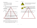


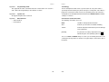
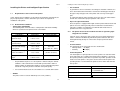


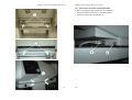

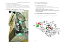
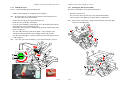
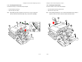
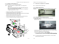
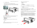

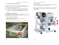
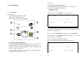
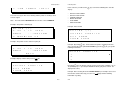
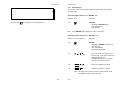


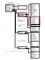
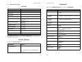

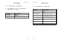
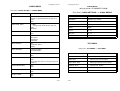


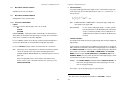
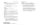
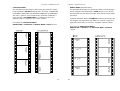
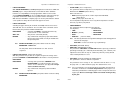
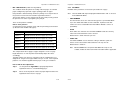

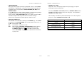

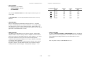

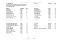
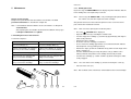

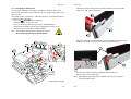
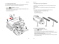
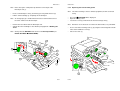
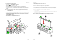


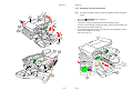
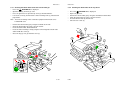
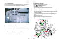
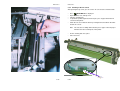

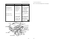
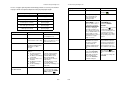
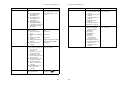
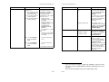
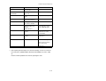
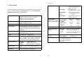

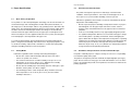
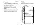
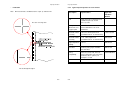
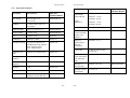
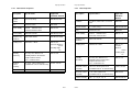
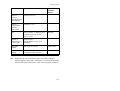

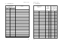


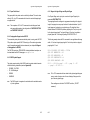
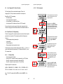
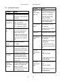


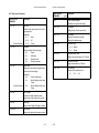
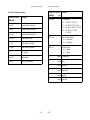

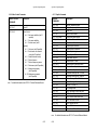
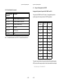

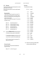
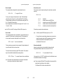

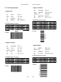
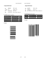
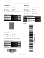


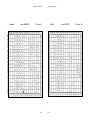
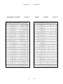
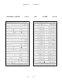
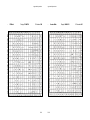

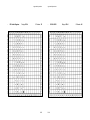
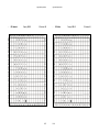
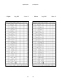

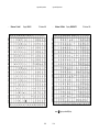
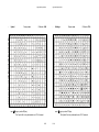
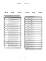


![User`s Guide [Printer/Copier/Scanner]](http://vs1.manualzilla.com/store/data/005987700_1-4ebf6f5f2843ec6fc8ace3e9735a6825-150x150.png)