1
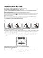
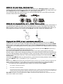
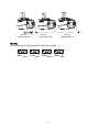
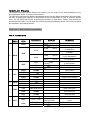
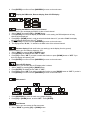
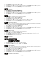
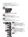
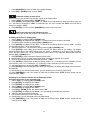
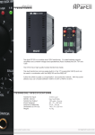
MB150 USER MANUAL (V2.00) Elektralite 70 Sea Lane, Farmingdale N.Y. 11735 U.S.A. Tel (+1)-516-249-3662 Fax (+1)-516-249-8870 www.myelektralite.com For your own safety, please read this user manual carefully before installing MB150. Every person involved with the installation, operation and maintenance of MB150 has to: -be qualified -follow carefully the instructions of this manual Introduction: Thank you for choosing MB150. When you unpack MB150, there should be in the box the fixture, a power cable, a DMX XLR cable, a safety cable and a CD. Please check carefully that there is no damage caused in shipping. If you notice any damage then immediately let your shipper know and the dealer from whom you purchased MB150. Features: operation mode is by DMX 512 utilizing (8 channels) or stand alone or sound activation. pan and tilt movement : 8 bit resolution for smooth and precise motion pan : 156° rotation / tilt : 90° rotation speed of pan/tilt movement adjustable strobe/shutter : high speed dual-blade shutter, 0-10Hz or random strobe dimmer : mechanical adjustable from 0% to 100% colors : 1 color wheel with 9 dichroic filters plus white, with rainbow effect gobos : 1 rotating gobo wheels, The wheel consist of 7 adjustable rotating gobos plus open, The wheel has ability to also shake the gobos. auto-program: 8 preprograms can be selected display: can be inverted (180)° when MB150 is hung upside down. local or remote resetting of motors auto test for all functions value of each DMX-channel can be displayed editable program: edit and save a program to the on board processor using either the controls on the front panel or using an external controller like an Elektralite CP-20. A maximum 48 scenes/cues/looks can be saved on board. The resultant saved program can be played back from the “run” menu accessed from the front display panel - 1 - Safety Instructions. This device has left the factory in perfect condition. In order to maintain this condition and to ensure a safe operation, it is absolutely necessary for the user to follow the safety instructions and warning notes written in this user manual. MB150 is a high voltage fixture. Be careful when dealing with high voltages. Please read this manual. If you do not read this manual and damages occur to MB150, then it could void the warranty. During shipping, MB150 may have been exposed to high temperature changes or humidity changes. So, as a precaution, do not switch MB150 on immediately. Condensation can damage MB150 so leave MB150 switched off until it has reached room temperature. The electric connection must be carried out by a qualified person and it is absolutely essential that MB150 be grounded. Always disconnect MM150 from the power source, when the device is not in use or before cleaning it. Only unplug MB150 from the power cord. Never pull out the plug out by pulling on the power cord. Take care, MB150 will heat up when it is turned on and it will be very hot to touch. Please keep MB150 away from children and the general public. Please be intelligent and use common sense when operating MB150. If you don’t understand what that means, don’t touch the MB150! General Guidelines. MB150 is a lighting fixture for professional use on stages, in clubs, theatres, etc. MB150 should only be operated at 120 volts and only indoors. MB150 should not be operated 24/7 (24 hours a day; 7 days a week). MB150 needs operation breaks to ensure that it will work for a long time without problems. Please do not shake MB150 and avoid using brute force when installing or operating it. When choosing the location to install MB150, please make sure that it is not exposed to extreme heat, moisture or dust. The minimum distance between MB150 and the illuminated surface must be more than 3 feet. Always mount MB150 with an appropriate safety cable. If you use the quick lock cam to hang MB150, please make sure the 4 quick lock fasteners are locked into position correctly. Operate MB150 only when you are familiar with the features on the fixture. Do not permit operation by persons not qualified for operating it. All modifications to MB150 will invalidate the warranty. There are absolutely no exceptions. If MB150 is operated in any way different to the ones described in this manual, MB150 maybe damaged and the guarantee will be void. - 2 - Installation Instructions. a) Installing or replacing the lamp Only install the lamp when MB150 is unplugged from 120 volts. The lamp must be replaced when it has reached the end of its lamp life or if it is damaged or deformed. Before replacing the lamp let the lamp cool down. During operation, the lamp can reach very high temperature. During the installation of the lamp do not touch the glass bulbs with bare hands. Always use a cloth to handle the lamps during insertion and removal. Your hands can leave a residue on the lamp which will cause it to deform when the lamp is hot. Do not install a lamp with a higher wattage. They generate temperatures higher than MB150 operating temperature and will damage the fixture both physically and electronically. For the installation, you need one Osram HSD 150/70 lamp : Procedure : 1 2 3 4 1) Unscrew the 2 screws on the back of the housing, holding the plate where the lamp is located. 2) Gently pull the socket holder using the knob in the middle. 3) Carefully insert the lamp into the socket. Please remember there is only one way to insert the lamp. Look at the holes in the lamp socket and compare with the lamp’s pins. Gently slide the lamp and its lamp holder back into place and fasten the 2 screws. 4) On the access plate there are 3 small screws marked 1, 2 and 3.which are used to adjust the lamp. You can adjust the 3 screws to fine-tune the position of the lamp and get the maximum light output. Please remember the lamp is not hot-restrike. You must wait approximately 10 minutes before you can restrike the lamp. Do not ever operate MB150 with the cover open. The lamp is a discharge lamp. All discharge lamps, irregardless of the manufacturer or type, are very volatile and can explode. Great caution must be exercised when working with these lamps otherwise serious injury can happen. - 3 - b) Mounting MB150 The installation of MB150 has to be built and constructed in a way that it can hold 10 times the weight for 1 hour without any deformation. The installation must always be secured with a secondary safety device (a safety cable or chain for example). Never stand directly below MB150 when mounting, removing or servicing MB150. The installer should make sure that MM150 is installed correctly and that the installation is checked by an expert on a regular basis. If you are a rental house utilizing MB150, then use the appropriate half coupler (½ cheeseboro) or “C” clamp to secure the fixture to the truss or pipe. Remember to tighten down the cheeseboro or “C” clamp before raising the truss. Don’t laugh! It has been done before now. Fixtures hopping down a truss is not a safe sight to see!! Caution: MB150 should be installed outside areas where people can reach it, walk by it or be seated underneath it when being installed. Overhead mounting requires experience including, amongst other things, calculating the working load limits and installation material being used. Periodic safety inspections should be done of MB150 as the fixture does move. If you do not have the qualifications and experience, do not attempt the installation. Improper installation can result in bodily injury to yourself or others. Before mounting make sure that the installation area can hold a minimum point load of 10 times MB150’s weight. Once installed then connect MB150 to the correct power source. 120 volts A.C. Please refer to the picture below: - 4 - DMX-512 Control Connection Connect the provided XLR cable to the female 3-pin XLR output of your Elektralite CP10xt or other DMX controller. The other end should be connected to the male 3-pin XLR input of MB150. Then daisy-chain out of the first MB150 and into the next MB150. Never “Y” split the DMX connection. If you need more cable, then it should be two core, screened cable fitted with a 3 pin XLR input and output connector. Please refer to the diagram below. DMX-512 connection with DMX terminator For installations where the DMX cable has to run a long distance or is in an electrically “noisy” environment, it is recommended that a DMX terminator is used. This helps prevent corruption of the digital control signal. The DMX terminator is simply a 3 pin XLR plug (male) with a 120 Ω resistor connected between pins 2 and 3. It is then plugged into the output XLR socket of the last MB150 in the chain. Please see illustration below. Projector DMX start address selection All MB150s need be given a DMX starting address when using a DMX signal, so that the correct MB150 responds to the correct control signals. This digital starting address is the channel number from which MB150 starts to “listen” to the digital control information sent out from the Elektralite CP10xt or other DMX controller. The allocation of this starting address is done by setting the correct number on the display located on the base of MB150. You can set the same starting address for all fixtures or group of fixtures, like all the MB150s in your plot, or you can make different address for each individual fixture. If you set the same address, all the fixtures will start to “listen” to the same control signal from the same channel number. In other words, changing the settings of one channel will affect all the fixtures simultaneously. If you set a different address, each unit will start to “listen” to the channel number you have set, based on the quantity of control channels of the fixture. That means changing the settings of one channel will affect only the selected fixture. In the case of this MB150, which is an 8 channel fixture, you should set the starting address of the first unit to 1, the second MB150 to 9 (8 + 1), the third to 17 (16 + 1), and so on. Note: After switching on, MB150 will automatically detect whether DMX 512 data is received or not. If the data is received, the display will show "A.001" or whatever the address is set to, like “A.017” If there is no data received at the DMX-input, the display flashes "A001" or whatever the actually set address is. The important thing to remember is the address is flashing. Now this situation can occur if: - the 3 PIN XLR plug (cable with DMX signal from the controller) is not connected to the input of MB150. or the controller is switched off or defective. or if the cable or connector is defective or if the signal wires are swap in the input connector. In others words, pins 1, 2 and/or 3 are not the same at both ends. Believe it or not this is very easy to do if the person making the cable does not look at the pin numbers in the connector. The numbers of the pins and the color of the cable need to match. Don’t just “look” at the cable and assume they are correct! Also Note: If the lamp is on, then the display will show "A00.1" or whatever the actually address is set to. If the lamp is off, then the display will show "A001". Note the PERIOD! - 5 - fixture 1 starting address 1 fixture 2 starting address 9 fixture 3 starting address 17 Note: The modes of DMX 512 data and lamp are shown via the display: . . DMX OK Lamp on . NO DMX Lamp on . NO DMX Lamp off - 6 - DMX OK Lamp off Display Panel The Display Panel offers several features: for example, you can simply set the starting address, run the pre-programmed “shows” or reset the fixtures motors. The main menu is accessed by pressing the Mode/esc-button until the display starts flashing. Browse through the menu by pressing the Up-button or Down-button. Press the Enter-button in order to select the desired menu. You can change the selection by pressing the Up-button or Down-button. Confirm every selection by pressing the Enter-button. You can leave every mode by pressing the Mode/esc-button. The functions provided are described in the following sections. Default settings shaded. Main functions Main menu Sub menu Extension Display Function ADDR VALU SLAV A001~A511 (AXXX) ON/OFF (SLAV) DMX address setting Slave setting Automatic Program Run in Stand Alone Automatic Program Run as Master Sound-controlled Program Run in Stand Alone Sound-controlled Program Run as Master Display the DMX 512 value of each channel Reverse display Shut off LED display ALON (AU-A) MAST (AU-M) ALON (SO-A) MAST (SO-M) AUTO RUN 0 MODE SOUN VALU 1 SET 2 ADJU 3 TIME 4 EDIT D-XX D–00 (DXXX) ON/OFF ON/OFF DISP RDIS CLDI RPAN ON/OFF Pan Reverse RTIL ON/OFF Tilt Reverse REST LODA VER LADJ TEST MATI ON/OFF V-1.0~V-9.9 ON/OFF T–01 ~ T–30 0000~9999 (hours) Reset Restore factory settings Software version Lamp adjustment Test function of each channel Fixture running time LATI 0000~9999 (hours) Lamp running time CLMT ON/OFF Clear fixture time CLLT ON/OFF Clear lamp time STEP S–01 ~ S–48 SC01 ~ SC48 C–01 ~ C–30 TIME (sec.) CNIN 01XX (00~FFH) 30XX (00~FFH) T – – X (1~9) ON/OFF - 7 - Steps of Program Run Edit the channels of each scene Time for each scene Edit program via controller - Main menu 1 (It looks like node in the display but it actually is Mode!!) 1. Press [MODE/ESC] to enter the main menu "MODE" (display flashing) 2. Press [ENTER] and select "ADDR", “RUN” or "DISP" by pressing [UP] or [DOWN] button. 3. Press [ENTER] for selecting the desired sub menu. - DMX address setting, Slave setting - DMX address setting With this function, you can adjust the desired DMX-address via the display panel. 1. Select “VALU“ by pressing [UP] or [DOWN] button. 2. Press [ENTER], adjust the DMX address by pressing [UP] or [DOWN] button. 3. Press [ENTER] to confirm or pressing [MODE/ESC] to return to main menu. - Slave setting With this function, you can make the fixture as slave. 1. Select “SLAV” by pressing [UP] or [DOWN] button. 2. Press [ENTER], the display shows “ON” or “OFF”. 3. Press [UP] to select “ON” if you wish to enable this function or press [DOWN] to select “OFF” if you don’t. 4. Press [ENTER] to confirm or press [MODE/ESC] to return to main menu. - Program Run, Master setting With the function "RUN", you can run the internal program. You can set the number of steps under Step. You can edit the individual scenes under Edit. You can run the individual scenes either automatically (AUTO), i.e. with the adjusted Step-Time or sound-controlled (SOUN). The selection "ALON" means Stand Alone-mode and "MAST" that the device is defined as master. 1. Select "AUTO" or "SOUN" by pressing [UP] or [DOWN] button. 2. Press [ENTER] for selecting the desired extension menu. 3. Select "ALON" or "MAST" by pressing [UP] or [DOWN] button. - 8 - 4. Press [ENTER] to confirm or Press [MODE/ESC] to return to the main menu. - Display the DMX-value, Reverse display, Shut off LED display - Display the DMX 512 value of each channel With this function you can display the DMX 512 value of each channel. 1. Select "VALU" by pressing [UP] or [DOWN] button. 2. Press [ENTER] to confirm; the display shows“D-00”. In this setting, the DMX-adjustment of every channel will be displayed. 3. Press [UP] or [DOWN] button in order to select the desired channel. If you select “D-08” the display will only show the DMX-value of the 8th channel. 4. Press [ENTER] to confirm or Press [MODE/ESC] to return to the main menu. 5. The display shows "D- XX“, ”X” stands for the DMX-value of the selected channel. - Reverse display (Kinda useful when your staring up at the display from the ground). With this function you can rotate the display by 180°. 1. Select "RDIS" by pressing [UP] or [DOWN] button. 2. Press [ENTER], the display shows “ON” or “OFF”. 3. Press [UP] to select “ON” if you wish to enable this function or press [DOWN] button to “OFF” if you don’t; the display will rotate by 180°. 4. Press [ENTER] to confirm or Press [MODE/ESC] to return to the main menu. - Shut off LED display With this function you can shut off the LED display after 2 minutes. 1. Select "CLDI" by pressing [UP] or [DOWN] button. 2. Press [ENTER], the display shows “ON” or “OFF”. 3. Press [UP] to select “ON” if you wish to enable this function or press [DOWN] button to “OFF” if you don’t. 4. Press [ENTER] to confirm or Press [MODE/ESC] to return to the main menu. - Main menu 2 1. Press [MODE/ESC] to enter the main menu (display flashing). 2. Press [UP] or [DOWN] button. to select “SET”. Press [ENTER]. - Pan Reverse With this function you can reverse the Pan-movement. 1. Select “RPAN” by pressing [UP] or [DOWN] button. - 9 - 2. Press [ENTER], the display shows “ON” or “OFF”. 3. Press [UP] to select “ON” if you wish to enable this function or press [DOWN] button to “OFF” if you don’t. 4. Press [ENTER] to confirm or Press [MODE/ESC] to return to the main menu. - Tilt Reverse With this function you can reverse the Tilt-movement. 1. Select “RTIL” by pressing [UP] or [DOWN] button. 2. Press [ENTER], the display shows “ON” or “OFF”. 3. Press [UP] to select “ON” if you wish to enable this function or press [DOWN] button to “OFF” if you don’t. 4. Press [ENTER] to confirm or Press [MODE/ESC] to return to the main menu. - Reset With this function you can Reset the device via the Control Board. 1. Select “REST” by pressing [UP] or [DOWN] button. 2. Press [ENTER], the display shows “ON” or “OFF”. 3. Press [UP] to select “ON” if you wish to enable this function or “OFF” if you don’t. 4. Press [ENTER] to confirm or Press [MODE/ESC] to return to the main menu. - Restore factory settings With this function you can restore the factory settings of the device. All settings will be set back to the default values (shaded). Please remember that Any edited scenes will be lost. 1. Select “LODA” by pressing [UP] or [DOWN] button. 2. Press [ENTER], the display shows “ON” or “OFF”. 3. Press [UP] to select “ON” if you wish to enable this function or press [DOWN] button to “OFF” if you don’t. 4. Press [ENTER] to confirm or Press [MODE/ESC] to return to the main menu. - Software version With this function you can display the software version of the device. 1. Select “VER” by pressing [UP] or [DOWN] button. 2. Press [ENTER], the display shows “V-X.X”, “X.X“ stands for the version number, e.g. “V-1.0”, “V-2.6”. 3. Press [MODE/ESC] to return to the main menu. - Main menu 3 1. Press [MODE/ESC] to enter the main menu (display flashing). 2. Press [UP] or [DOWN] button to select “ADJU”. Press [ENTER]. - Lamp adjustment With this function you can adjust the lamp via the Control Board. The shutter opens and the lamp can be adjusted. In this mode, the device will not react to any control signal. 1. Select “LADJ” by pressing [UP] or [DOWN] button. 2. Press [ENTER], the display shows “ON” or “OFF”. 3. Press [UP] to select “ON” if you wish to enable this function or press [DOWN] button to “OFF” if you don’t. 4. Press [ENTER] to confirm or Press [MODE/ESC] to return to the main menu. - Test function of each channel - 10 - With this function you can test each channel on its (correct) function. 1. Select “TEST” by pressing [UP] button. 2. Press [ENTER], the display shows “T-XX”, “X” stands for the channel number. 3. The current channel will be tested. 4. Select the desired channel by pressing [UP] or [DOWN] button. 5. Press [ENTER] to confirm or Press [MODE/ESC] to return to the main menu. - Main menu 4 1. Press [MODE/ESC] to enter the main menu (display flashing). 2. Press [UP] or [DOWN] button to select “TIME”. Press [ENTER]. - Fixture running time With this function you can display the running time of the fixture. 1. Select “MATI” by pressing [UP] or [DOWN] button. 2. Press [ENTER], the display shows “XXXX”, “X“ stands for the number of hours. 3. Press [ENTER] to confirm or Press [MODE/ESC] to return to the main menu. - Lamp running time With this function you can display the running time of the lamp. 1. Select “LATI” by pressing [UP] button. 2. Press [ENTER], the display shows “XXXX”, “X“ stands for the number of hours. 3. Press [MODE/ESC] to return to the main menu. - Clear fixture time With this function you can clear the running time of the fixture. 1. Select “CLMT” by pressing [UP] or [DOWN] button. 2. Press [ENTER], the display shows “ON” or “OFF”. 3. Press [UP] to select “ON” if you wish to enable this function or press [DOWN] button to “OFF” if you don’t. 4. Press [ENTER] to confirm or Press [MODE/ESC] to return to the main menu. - Clear lamp time With this function you can clear the running time of the lamp. Please clear the lamp time every time you replace the lamp. 1. Select “CLLT” by pressing [UP] or [DOWN] button. 2. Press [ENTER], the display shows “ON” or “OFF”. 3. Press [UP] to select “ON” if you wish to enable this function or press [DOWN] button to “OFF” if you don’t. 4. Press [ENTER] to confirm or Press [MODE/ESC] to return to the main menu. - Main menu 5 - 11 - 1. Press [MODE/ESC] to enter the main menu (display flashing). 2. Press [UP] or [DOWN] button to select “EDIT”. - Define the number of steps in Run With this function you can define the number of steps in the Program Run. 1. Select “STEP” by pressing [UP] or [DOWN] button. 2. Press [ENTER], the display shows “S-XX”, “X” stands for the total amount of steps you want to save, so you can call up to 48 scenes in “RUN”. For example if the “XX” is 05, it means that “RUN” will run the first 5 scenes you saved in “EDIT”. 3. Press [ENTER] to confirm or Press [MODE/ESC] to return to the main menu. - Editing the channels of the individual scenes With this function you can edit the program to be called up in Run. a) Editing via the fixure’s display panel 1. Select “SC01” by pressing [UP] or [DOWN] button. 2. Press [ENTER], the display shows “SCXX”, “X” stands for the scene number to be edited. 3. Change the scene number by pressing [UP] or [DOWN] button. 4. Press [ENTER], the display shows “C-X”, “X” stands for the channel number Such as “C-01”, it means you are editing channel 1 of the selected scene. 5. Select the channel no. you would like to edit by pressing [UP] or [DOWN] button. 6. Press [ENTER] to enter editing for the selected channel. The fixture reacts to your settings. The display shows the DMX value of the edited channel. Such as “ 04XX”, it stands for in the channel 04 of the editing scene, the DMX value is XX , XX is a hexadecimal number value “01-FF”.Adjust the desired DMX value by pressing [UP] or [DOWN] button. 7. Press [ENTER] in order to edit other channels of this scene. 8. Repeat steps 5-9 until you finish setting all the DMX values for all channels of this scene. 9. Once all the channels completed, the display will flash “TIME” 10. Press [ENTER] to edit the time needed, the display shows “t--X”,“X” stands for the time needed to run the current scene, value “1-9”. For example, “t--2” means you need 2 seconds to run the current scene. 11. Adjust the desired time by pressing [UP] or [DOWN] button. 12. Press [ENTER] to save the settings for the scene you are editing, the display will change to the next scene automatically. 13. Repeat step 3-14 to edit and other scenes, you can edit and save a maximum of 48 scenes. 14. Press [MODE/ESC] to exit. The number of steps can be defined under “STEP” and the scenes can be called up under “RUN” b) Editing via an external controller like an Elektralite CP10xt Call up the first scene in your controller now. 1. Select “SC01” by pressing [UP] or [DOWN] button. 2. Press [ENTER], the display shows “SC01”. 3. Press [ENTER], the display shows “C-01”. 4. Select "CNIN" by pressing [UP] or [DOWN] button. 5. Press [ENTER], the display shows "OFF". 6. Press [UP] or [DOWN] button .the display shows "ON". 7. Press [ENTER], the display shows "SC02". You successfully downloaded the first scene. 8. Adjust the Step-time as described above. 9. Call up the second scene in your controller now. 10. Repeat steps 5-9 until all desired scenes are downloaded. 11. Press [MODE/ESC] to exit. The number of steps can be defined under “STEP” and the scenes can be called up under “RUN” - 12 - MB150’S FIXTURE PROFILE: DMX channel´s functions and their values : Channel 1 - Color Wheel 1 : 0-12 Open / white 13-25 COL 1 26-38 COL 2 39-51 COL 3 52-64 COL 4 65-77 COL 5 78-90 COL 6 91-103 COL 7 104-116 COL 8 117-127 COL 9 128-187 Forwards rainbow effect from fast to slow 188-193 No rotation 194-255 Backwards rainbow effect from slow to fast Channel 2 - Rotating gobos, cont. rotation : 0-13 Open 14-27 Rot. gobo 1 (metal) 28-41 Rot. gobo 2 (metal) 42-55 Rot. gobo 3 (metal) 56-69 Rot. gobo 4 (metal) 70-83 Rot. gobo 5 (metal) 84-97 Rot. gobo 6 (metal) 98-115 Rot. gobo 7 (metal) 116-135 Rot. gobo 1 (metal) shake 136-155 Rot. gobo 2 (metal) shake 156-175 Rot. gobo 3 (metal) shake 176-195 Rot. gobo 4 (metal) shake 196-215 Rot. gobo 5 (metal) shake 216-235 Rot. gobo 6 (metal) shake 236-255 Rot. gobo 7 (metal) shake - 13 - Channel 3 0-7 rotating gobo rotation : No rotation 8-127 forwards gobo rotation from fast to slow 128-135 No rotation 136-255 Backwards gobo rotation from slow to fast Channel 4 - Shutter, strobe: 0-31 Shutter closed 32-63 Dimmer (close to open) 64-95 Strobe effect slow to fast 96-127 No function (shutter open) 128-159 Pulse-effect in sequences 160-191 No function (shutter open) 192-223 Random strobe effect slow to fast 224-255 No function (shutter open) Channel 5 - PAN movement : Channel 6 - TILT movement : 0-7 No Rotation of the mirror barrel 8-127 Forward rotation of the barrel from fast to slow 128-135 No Rotation of the barrel 136-255 Backward rotation of the barrel from slow to fast Channel 7 - Speed pan/tilt movement: 0 max speed 5-225 max to min speed 226-235 blackout by movement 236-245 blackout by all wheel changing 246-255 no function - 14 - Channel 8 – reset, internal programs: 0-19 color change normal 20-39 color change to any position 40-59 No function 60-79 No function 80-99 Motor reset 100-119 Internal program 1 120-139 Internal program 2 140-159 Internal program 3 160-179 Internal program 4 180-199 Internal program 5 200-219 Internal program 6 220-239 Internal program 7 240-255 Internal program 8 - 15 - CLEANING AND MAINTENANCE The following points have to be considered during the inspection: 1) All screws for installing the devices or parts of the device have to be tightly connected and must not be corroded. 2) There must not be any deformation on the fixture or the suspension point. In other words check the truss, ceiling, threaded rods or whatever is holding up the fixture. That also includes the safety cable or chain! 3) Mechanical moving parts must not show any traces of wearing and must not rotate out of balance. 4) The electric power supply cables must not show any damage, material fatigue or sediment. We recommend frequent cleaning of the device. Please use a moist, lint- free cloth. Never use alcohol or solvents. PLEASE clean around the fans and any air vents. If you do not do this regularly you will dramatically decrease the life of the lamp and the fixture itself. If it cannot “breath” it is going to die!!! Use a vacuum cleaner NOT an air hose/can. Unless you prefer to blow the dust all over the colors and gobos!!! There are no serviceable parts inside the device, except for the lamp. Please refer to the instructions under “Installation instructions” for lamp change. Should you need any spare parts, please order genuine parts from your local dealer. TECHNICAL SPECIFICATIONS Power supply : □98VAC,50Hz;□120VAC,50Hz;□208VAC,50Hz;□220VAC,50Hz;□230VAC,50Hz;□240VAC,50Hz; Power consumption : max. □230W Lamp : □ HSD150 G12 socket, Metal Halide; Motors : 6 micro motors Packing dimensions : 67x37x34cm (26½”x14½”x13½”) Net weight : □10.5KGS (23.1 pounds) Gross weight: □12.5KGS (27½ pounds) Remark : We obviously try not to have any errors in the manual but errors and omissions for information in this manual has to be excepted. Further all information is subject to change without prior notice. - 16 - Other Elektralite Products include : [Also check out our website at www.myelektralite.com] CP-3 Controller. CP-10xt Controller. CP-16 /24 Controller. - 17 - CP-20xt Controller. TurboFog + Fog Machine. - 18 -