1
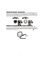
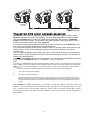
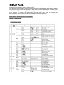
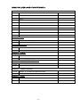
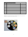
Paintcan USER MANUAL (V3.3) Elektralite 70 Sea Lane, Farmingdale N.Y. 11735 U.S.A. Tel (+1)-516-249-3662 Fax (+1)-516-249-8870 www.myelektralite.com For your own safety, please read this user manual carefully before installing Paintcan. Every person involved with the installation, operation and maintenance of Paintcan has to: -be qualified -follow carefully the instructions of this manual Introduction: Thank you for choosing Paintcan. When you unpack Paintcan, there should be in the box the fixture, a power cable, a safety cable and a CD. Please check carefully that there is no damage caused in shipping. If you notice any damage then immediately let your shipper know and the dealer from whom you purchased Paintcan. Features: operation mode is by DMX 512 utilizing (8 channels). colors: 1 color wheel with 3 dichrioc filters plus CT to 5600ºK, White and rainbow effect. strobe : via color wheel’s closed and open position being utilized. dimmer : in built electronic fully adjustable from 0% to 100% Advanced Cyan Magenta and Yellow color mixing system . auto-program: 8 preprograms can be selected display: can be inverted (180)° when Paintcan is hung upside down. local or remote resetting of motors auto test for all functions value of each DMX-channel can be displayed editable program: edit and save a program to the on board processor using either the controls on the front panel or using an external controller like an Elektralite CP-20. A maximum 48 scenes/cues/looks can be saved on board. The resultant saved program can be played back from the “run” menu accessed from the front display panel - 1 - Safety Instructions. This fixture has left the factory in perfect condition. In order to maintain this condition and to ensure a safe operation, it is absolutely essential for the user to follow the safety instructions and warning notes written in this user manual. Paintcan is a high voltage fixture. Be careful when dealing with high voltages. Please read this manual. If you do not read this manual and damages occur to Paintcan, then it could void the warranty. During shipping, Paintcan may have been exposed to high temperature changes or humidity changes. So, as a precaution, do not switch Paintcan on immediately. Condensation can damage Paintcan so leave Paintcan switched off until it has reached room temperature. The electric connection must be carried out by a qualified person and it is absolutely essential that Paintcan be grounded. Always disconnect Paintcan from the power source, when the device is not in use or before cleaning it. Only unplug Paintcan from the power cord. Never pull out the plug out by pulling on the power cord. Take care, Paintcan will heat up when it is turned on and it could be very hot to touch. Please keep Paintcan away from children and the general public. Please be intelligent and use common sense when operating Paintcan. If you don’t understand what that means don’t touch the Paintcan! General Guidelines. Paintcan is a lighting fixture for professional use on stages, in clubs, theatres, churches etc. Paintcan should only be operated at 120 volts and only indoors. Paintcan should not be operated 24/7 (24 hours a day; 7 days a week). Paintcan needs operation breaks to ensure that it will work for a long time without problems. Please do not shake Paintcan and avoid using brute force when installing or operating it. Please remember just because you cannot see any output of light from the fixture that does not mean the fixture is off. Turn the fixture off when not using it. If you don’t, fans can accumulate dust and dirt. Lamp life will be ‘ticking’ down, if a preheat setting above zero has been chosen. When choosing the location to install Paintcan, please make sure that it is not exposed to extreme heat, moisture or dust. The minimum distance between Paintcan and the illuminated surface must be more than 3 feet. Always mount Paintcan with an appropriate safety cable. If you use the quick lock cam to hang Paintcan, please make sure the 4 quick lock fasteners are locked into position correctly. Operate Paintcan only when you are familiar with the features on the fixture. Do not permit operation by persons not qualified for operating it. All modifications to Paintcan will invalidate the warranty. There are absolutely no exceptions. If Paintcan is operated in any way different to the ones described in this manual, Paintcan maybe damaged and the guarantee will be void. - 2 - Installation Instructions. a) Installing or replacing the lamp Only install the lamp when Paintcan is unplugged from 120 volts. The lamp must be replaced when it has reached the end of its lamp life or if it is damaged or deformed. Before replacing the lamp let the lamp cool down. During operation, the lamp can reach very high temperature. During the installation of the lamp do not touch the glass bulbs with bare hands. Always use a cloth to handle the lamps during insertion and removal. Your hands can leave a residue on the lamp which will cause it to deform when the lamp is hot. Do not install a lamp with a higher wattage. They generate temperatures higher than Paintcan operating temperature and will damage the fixture both physically and electronically. For the installation, you need one GLA or GLC 120v halogen lamp : Procedure : 1) Unscrew the 2 screws on the back of the housing, holding the plate where the lamp is located. 2) Gently pull the socket holder using the knob in the middle. 3) Carefully insert the lamp into the socket. Please remember there is only one way to insert the lamp. Look at the holes in the lamp socket and compare with the lamp’s pins. Gently slide the lamp and its lamp holder back into place and fasten the 2 screws. 4) On the access plate there are 3 small screws marked A, B and C. which are used to adjust the lamp. You can adjust the 3 screws to fine-tune the position of the lamp and get the maximum light output. . LAMP:GLA 115V 575W Do not ever operate Paintcan with the cover open. All lamps, irregardless of the manufacturer or type, can be very volatile and can explode. Great caution must be exercised when working with these lamps otherwise serious injury can happen. Using different lamp manufacturers, where one has several fixtures being used together, can result in severe differences in the colors. So beware. Also incorrect lamp adjustment can result in both color differences and low output of the lamp. - 3 - b) Mounting Paintcan The installation of Paintcan has to be built and constructed in a way that it can hold 10 times the weight for 1 hour without any deformation. The installation must always be secured with a secondary safety device (a safety cable or chain for example). Never stand directly below Paintcan when mounting, removing or servicing Paintcan. The installer should make sure that Paintcan is installed correctly and that the installation is checked by an expert on a regular basis. If you are a rental house utilizing Paintcan, then use the appropriate half coupler (½ cheeseboro) or “C” clamp to secure the fixture to the truss or pipe. Remember to tighten down the cheeseboro or “C” clamp before raising the truss. Don’t laugh! It has been done before now. Fixtures hopping down a truss, is not a safe sight to see!! Caution: Paintcan should be installed outside areas where people can reach it, walk by it or be seated underneath it when being installed. Overhead mounting requires experience including, amongst other things, calculating the working load limits and installation material being used. Periodic safety inspections should be done of Paintcan. If you do not have the qualifications and experience, do not attempt the installation. Improper installation can result in bodily injury to yourself or others. Before mounting make sure that the installation area can hold a minimum point load of 10 times Paintcan’s weight. Once installed then connect Paintcan to the correct power source. 120 volts A.C. Do not connect it to a dimmer circuit, even if that dimmer circuit has a non dim setting. Do not connect to a circuit which has “high electrical noise” such as large AC motors which have not been correctly suppressed. This can interfere with the operation of the Paintcan causing it to ghost the lamp or pulse the dimmer. Please refer to the picture below: - 4 - DMX-512 Control Connection Connect the provided XLR cable to the female 5-pin XLR output of your Elektralite CP10xt or other DMX controller. The other end should be connected to the male 5-pin XLR input of Paintcan. Then daisy-chain out of the first Paintcan and into the next Paintcan. Never “Y” split the DMX connection. If you need more cable, then it should be two core, screened cable fitted with a 5 pin XLR input and output connector. Please refer to the diagram below. 1 5 4 3 2 DMX-512 connection with DMX terminator For installations where the DMX cable has to run a long distance or is in an electrically “noisy” environment, it is recommended that a DMX terminator is used. This helps prevent corruption of the digital control signal. The DMX terminator is simply a 5 pin XLR plug (male) with a 120 Ω resistor connected between pins 2 and 3. It is then plugged into the output XLR socket of the last Paintcan in the chain. Please see illustration below. 1 5 3 2 120 - 5 - Ω 4 Projector DMX start address selection All Paintcans need be given a DMX starting address when using a DMX signal, so that the correct Paintcan responds to the correct control signals. This digital starting address is the channel number from which Paintcan starts to “listen” to the digital control information sent out from the Elektralite CP10xt or other DMX controller. The allocation of this starting address is done by setting the correct number on the display located on the base of Paintcan. You can set the same starting address for all fixtures or group of fixtures, like all the Paintcans in your plot, or you can make different address for each individual fixture. If you set the same address, all the fixtures will start to “listen” to the same control signal from the same channel number. In other words, changing the settings of one channel will affect all the fixtures simultaneously. If you set a different address, each unit will start to “listen” to the channel number you have set, based on the quantity of control channels of the fixture. That means changing the settings of one channel will affect only the selected fixture. In the case of this Paintcan, which is an 8 channel fixture, you should set the starting address of the first unit to 1, the second Paintcan to 9 (8 + 1), the third to 17 (16 + 1), and so on. Note: After switching on, Paintcan will automatically detect whether DMX 512 data is received or not. If the data is received, the display will show "A.001" or whatever the address is set to, like “A.017” If there is no data received at the DMX-input, the display flashes "A001" or whatever the actually set address is. The important thing to remember is the address is flashing. Now this situation can occur if: - the 5 PIN XLR plug (cable with DMX signal from the controller) is not connected to the input of Paintcan. or the controller is switched off or defective. or if the cable or connector is defective or if the signal wires are swap in the input connector. In others words, pins 1, 2 and/or 3 are not the same at both ends. Believe it or not this is very easy to do if the person making the cable does not look at the pin numbers in the connector. The numbers of the pins and the color of the cable need to match. Don’t just “look” at the cable and assume they are correct! If the Paintcans in a DMX chain overlap by one channel, it means that channel 8 of the first fixture and channel 1 of the second fixture will be controlled together. The result is, it will appear that fixture one will have a “mind-of-its-own” and do things without any control. This is the inbuilt programs that you have activated when trying to control the color wheel (channel 1) of the second fixture. Go back and check the dmx addresses. - 6 - Display Panel The Display Panel offers several features: for example, you can simply set the starting address, run the pre-programmed “shows” or reset the fixtures motors. The main menu is accessed by pressing the Mode/esc-button until the display starts flashing. Browse through the menu by pressing the Up-button or Down-button. Press the Enter-button in order to select the desired menu. You can change the selection by pressing the Up-button or Down-button. Confirm every selection by pressing the Enter-button. You can leave every mode by pressing the Mode/esc-button . The functions provided are described in the following sections. Default settings shaded. Main functions - 7 - - 8 - Please note if the preheat value is 0, when channel 6 (the dimmer channel) is at 0 dmx value, then the lamp will be completely off. This is recommended for places where the fixtures maybe run for several hours and where there will be a lot of “off” time for the fixture. For example, store displays or church services or industrial presentations. If using 0 preheat PLEASE make sure the lighting board actually will go down to 0 dmx value for the dimmer channel. There are boards that do NOT actually go to 0 dmx value. The display on the lighting board may say 0 but in actual fact the board does output a small dmx value like 1 or 2. That value is enough for the lamp to be ON and not OFF. A preheat value above 0 is good for lamp life when the fixture will be faded up and down regularly, or flashed/bumped up and down a lot. Working examples of this situation is in theatrical shows or rock-n-roll concerts. A preheat value stops the filament from firing from off to on and back again too quickly. If a preheat value is too high, the lamp will appear to be on and will of course never ‘appear’ to be off. This is called “GHOSTING” of the lamp. The preheat should be set, so the lamp filament is just ‘on’ and not really that visible to the naked eye. - 9 - - 10 - - 11 - - 12 - - 13 - - 14 - DMX VALUES AND FUNCTIONS : Channel 1 - Color Wheel 0-21 Closed (no light output) 22-43 44-65 Open / white 66-87 Color 1 Color 2 88-109 Color 3 110-127 Color Correction to 5600K 128-187 Forwards rainbow effect from fast to slow 188-193 No rotation 194-255 Backwards rainbow effect from slow to fast Channel 2 - Cyan 0-255 Cyan (0-white, 255-Cyan) Channel 3 - Magenta 0-255 Magenta (0-white, 255- Magenta) Channel 4 0-255 - Yellow Yellow (0-white, 255-Yellow) Channel 5 - Speed Of CMY And Dimmer 0-255 Speed Max ->Min Channel 6 0-255 Intensity 0- no output 255- Maximum Output Channel 7 0-255 Dimmer (intensity) Zoom Zoom 40 - Zoom 20 (Widest beam = 0, Smallest beam = 255) - 15 - Channel 8 – Lamp on/off, reset, internal programs 0-19 color change normal (snap to each color) 20-39 color change to any position (rolling through the colors) 40-59 no function 60-79 no function 80-99 Motor reset 100-119 Internal program 1 120-139 Internal program 2 140-159 Internal program 3 160-179 Internal program 4 180-199 Internal program 5 200-219 Internal program 6 220-239 Internal program 7 240-255 Internal program 8 Please note:- The color wheel with removable colors was added to the Paintcan features. If you have this new wheel please refer to the photo below on how to replace/remove colors. - 16 - ERROR MESSAGE When you turn on Paintcan, it will do a reset first. If everything is fine with it then you will see the DMX address on the display at the end of the reset procedure. If you get an 01er or 02er or 07er then you have a problem. You can of course get multi errors. The error codes will flash for 5 times and then the Paintcan will automatically start another reset to see if it can fix the problem. This will go on for a total of 3 resets. At the end of 3 resets if the Paintcan has less than 3 error messages then the channels that can work properly will do so and the ones showing the error will not work. If the Paintcan has 3 errors, then all the channels cannot work properly, so the Paintcan will not work. Here’s a list of the errors:- 01Er: (Color-wheel error) This message will appear after the reset of the fixture when the magnetic-indexing circuit malfunctions; meaning that the sensor failed or magnet missing or the stepper-motor is defective or the driver chip on the main circuit card. The result is that the color wheel is not located in the default position after the reset is completed. 02Er: (Cyan-color mixing leaves error) This message will appear after the reset of the fixture when the magnetic-indexing circuit malfunctions; meaning that the sensor failed or magnet missing or the stepper-motor is defective or the driver chip on the main circuit card. The cyan leaves are not located in the default position after the reset is completed. 07Er: (Zoom-error) This message will appear after the reset of the fixture when the magnetic-indexing circuit malfunctions; meaning the sensor failed or magnet missing or the stepper-motor is defective or the driver chip on the main circuit card. The zoom is not located in the default position after the reset is completed. CLEANING AND MAINTENANCE The following points have to be considered during the inspection: 1) All screws for installing the devices or parts of the device have to be tightly connected and must not be corroded. 2) There must not be any deformation on the fixture or the suspension point. In other words check the truss, ceiling, threaded rods or whatever is holding up the fixture. That also includes the safety cable or chain! 3) Mechanical moving parts must not show any traces of wearing and must not rotate out of balance. 4) The electric power supply cables must not show any damage, material fatigue or sediment. We recommend frequent cleaning of the device. Please use a moist, lint- free cloth. Never use alcohol or solvents. PLEASE clean around the fans and any air vents. If you do not do this regularly you will dramatically decrease the life of the lamp and the fixture itself. If it cannot “breath” it is going to die!!! Use a vacuum cleaner NOT an air hose/can. Unless you prefer to blow the dust all over the colors and gobos!!! There are no serviceable parts inside the device, except for the lamp. Please refer to the instructions under “Installation instructions” for lamp change. Should you need any spare parts, please order genuine parts from your local dealer. - 17 - TECHNICAL SPECIFICATIONS Power supply : □120VAC,60Hz Power consumption : max. □650W Lamp : □ GLA or GLC 575 only. Motors : 5 micro motors Packing dimensions : 48x35x46cm (19”x14”x18¼”) Net weight : □11KGS (24 pounds) Gross weight: □13KGS (29 pounds) Remark : We obviously try not to have any errors in the manual but errors and omissions for information in this manual has to be excepted. Further all information is subject to change without prior notice. Last updated June3rd 2010. - 18 - Other Elektralite Products include : [Also check out our website at www.myelektralite.com] CP-3 Controller. CP-10xt Controller. CP-16 /24 Controller. - 19 - CP-20xt Controller. - 20 -


![Di28.manual_eng [更新済み]](http://vs1.manualzilla.com/store/data/006248510_1-4715480d32b4655833aa4eb8b5d462bc-150x150.png)