1
Safety Precautions
Observe the following notices to ensure personal safety or to prevent accidents.
To ensure that you use this product correctly, read this User’s Manual thoroughly before use.
Make sure that you fully understand the product and information on safety.
This manual uses two safety flags to indicate different levels of danger.
WARNING
If critical situations that could lead to user’s death or serious injury is assumed by
mishandling of the product.
-Always take precautions to ensure the overall safety of your system, so that the whole
system remains safe in the event of failure of this product or other external factor.
-Do not use this product in areas with inflammable gas. It could lead to an explosion.
-Exposing this product to excessive heat or open flames could cause damage to the lithium
battery or other electronic parts.
CAUTION
If critical situations that could lead to user’s injury or only property damage is
assumed by mishandling of the product.
-To prevent excessive exothermic heat or smoke generation, use this product at the values
less than the maximum of the characteristics and performance that are assured in these
specifications.
-Do not dismantle or remodel the product. It could cause excessive exothermic heat or smoke
generation.
-Do not touch the terminal while turning on electricity. It could lead to an electric shock.
-Use the external devices to function the emergency stop and interlock circuit.
-Connect the wires or connectors securely.
The loose connection could cause excessive exothermic heat or smoke generation.
-Do not allow foreign matters such as liquid, flammable materials, metals to go into the inside
of the product. It could cause excessive exothermic heat or smoke generation.
-Do not undertake construction (such as connection and disconnection) while the power
supply is on. It could lead to an electric shock.
Copyright / Trademarks
-This manual and its contents are copyrighted.
-You may not copy this manual, in whole or part, without written consent of Panasonic
Industrial Devices SUNX Co., Ltd.
-Windows is a registered trademark of Microsoft Corporation in the United States and other
countries.
-All other company names and product names are trademarks or registered trademarks of
their respective owners.
PLC_ORG
Table of Contents
Before you start
1.Functions and Restrictions of the Unit ................................1-1
1.1 Features and Functions ............................................................................. 1-2
1.2 System Configuration ................................................................................ 1-3
1.2.1 Master Station (Master Unit) ......................................................................1-4
1.2.2 Slave Stations (Slave Unit, I/O Terminal, I/O Terminal Board, etc)...........1-5
1.2.3 Advanced Units Not to be Used for Slave Station System of “MEWNET-F”1-7
1.3 Unit Types.................................................................................................. 1-9
1.3.1 Remote I/O System "MEWNET-F" Components .......................................1-9
1.3.2 Transmission Cable .................................................................................1-10
1.3.3 I/O Cables and Power Supply Cable for I/O Terminal Board "For MIL
Connector Type" ...................................................................................1-10
1.3.4 Expansion Cable for I/O Terminal Unit ....................................................1-10
2.Part Names and Functions.....................................................2-1
2.1 FP2 Multi-wire Link Unit............................................................................. 2-2
2.2 Remote I/O master unit.............................................................................. 2-6
2.2.1 FP3 Remote I/O Master Unit (AFP3742) ...................................................2-6
2.3 Remote I/O Slave Unit ............................................................................... 2-8
2.3.1 FP2 Remote I/O Slave Unit (AFP2745) .....................................................2-8
2.3.2 FP3 Remote I/O Slave Unit (AFP3745) ...................................................2-10
2.4 I/O Terminal Board .................................................................................. 2-12
2.4.1 I/O Terminal Board Terminals Specifications ..........................................2-14
2.5 I/O Terminal Unit...................................................................................... 2-18
2.5.1 I/O Terminal Unit Terminals Specifications..............................................2-20
Unit Specifications.....................................................................3-1
3.1 General Specifications (Common to the System)...................................... 3-2
3.2 Performance Specifications (Common to the System) .............................. 3-3
3.3 Rating and Specifications of Components................................................. 3-4
3.3.1 Master Unit.................................................................................................3-4
3.3.2 Slave Unit...................................................................................................3-4
3.3.3 I/O Terminal Board.....................................................................................3-4
3.3.4 I/O Terminal Unit ........................................................................................3-6
3.4 Transmission Cable Specifications............................................................ 3-8
3.4.1 Recommended Cables...............................................................................3-8
3.4.2 Terminals ...................................................................................................3-9
3.5 Communication Time............................................................................... 3-10
3.5.1 Remote I/O Scan Time [TR].....................................................................3-10
3.5.2 Remote I/O Memory Access Time [TRM] ..................................................3-10
3.5.3 Input/Output Response Time for Remote I/O System [TRES].................3-11
4.Installation and Wiring ........................................................... 4-1
4.1 Preparation of MEWNET-F Components .................................................. 4-2
4.1.1 Master Station (Master Unit) ......................................................................4-2
4.1.2 Slave Station System (Slave Unit) .............................................................4-4
4.1.3 I/O Terminal Board (Slave Station) ............................................................4-6
4.1.4 I/O Terminal Unit (Slave Station) ...............................................................4-7
4.1.5 Reference (Check Flow Chart>..................................................................4-8
4.2 Power Up Sequence ................................................................................. 4-9
4.2.1 Remote I/O Mapping, Slave Station Connection Confirmation Mode........4-9
4.2.2 Remote I/O Mapping, Slave Station Connection Not Confirmed Mode .....4-9
4.2.3 Remote I/O Map Not Registered Mode......................................................4-9
5.Connection for the Remote I/O System ................................ 5-1
5.1 Connection for the Remote I/O System..................................................... 5-2
5.1.1 Description of Connection and Setting Procedure .....................................5-2
5.2 Connection Pattern for MEWNET-F .......................................................... 5-3
5.2.1 Connection Pattern A .................................................................................5-3
5.2.2 Connection Pattern B .................................................................................5-3
5.2.3 Connection Pattern C.................................................................................5-3
5.2.4 Connection Pattern D.................................................................................5-4
5.2.5 Connection Pattern E .................................................................................5-4
5.2.6 Connection Pattern F .................................................................................5-4
5.3 Procedure for Connecting and Setting Up................................................. 5-5
5.3.1 Preparation.................................................................................................5-5
5.3.2 Precedure 1 Wiring of Transmission Cables............................................5-6
5.3.3 Procedure 2 Master Station (Master Unit) Setting ...................................5-7
5.3.4 Procedure 3 Slave Station Setting ...........................................................5-8
5.3.5 Procedure 4 Power Up Sequence..........................................................5-10
6.Remote I/O Map ...................................................................... 6-1
6.1 Remote I/O Map ........................................................................................ 6-2
6.1.1 Configuration of Remote I/O Map ..............................................................6-2
6.1.2 Precautions When Allocating I/O Numbers for Slave Stations ..................6-3
6.2 Automatic I/O Number Allocation and Arbitrary I/O Number Allocation .... 6-5
6.2.1 Remote I/O Control According to Automatic Allocation .............................6-5
6.2.2 Remote I/O Control According to Arbitrary Allocation................................6-6
6.3 Arbitrary Allocation of Remote I/O Map..................................................... 6-8
6.3.1 Setting the Base Word Number .................................................................6-8
6.3.2 Setting the Number of Slots Used..............................................................6-9
6.3.3 Setting the I/O Type and Number of Points ...............................................6-9
7.Operation Modes for Controlling MEWNET-F ......................7-1
7.1 How to Change the Operation Mode (System Register Setting) ............... 7-2
7.1.1 Operation Mode Changeable.....................................................................7-2
7.1.2 How to Change the Remote I/O Operation Mode......................................7-2
7.1.3 System Registers for the Remote I/O Operating Mode .............................7-2
7.2 Remote I/O Control When an Error Occurs ............................................... 7-3
7.2.1 Operation Status When a Communication Error Occurs ...........................7-4
7.2.2 Operation When an Error Occurs in a Unit Connected to a Slave Station
System ....................................................................................................7-7
7.3 Slave Station Connection Confirmation Mode ........................................... 7-9
7.3.1 Slave Station Connection Confirmation Mode ...........................................7-9
7.3.2 Slave Station Connection Not Confirmed Mode ......................................7-10
7.4 Remote I/O Update Timing Method ......................................................... 7-11
7.4.1 Scan Asynchronous Mode .......................................................................7-11
7.4.2 Scan Time Synchronous Mode................................................................7-12
8.Control by MEWNET-F............................................................8-1
8.1 Functions of MEWNET-F........................................................................... 8-2
8.1.1 Remote I/O Control ....................................................................................8-2
8.1.2 Memory Access Function...........................................................................8-3
9.Troubleshooting......................................................................9-1
9.1 Finding the Cause of an Error and Correcting the Error ............................ 9-2
9.1.1 Finding the Cause of an Error....................................................................9-2
9.2 Self-diagnostic Functions of MEWNET-F .................................................. 9-3
9.2.1 Self-diagnostic Error Table ........................................................................9-3
9.3 Remote I/O Error Codes (DT9136(DT90136) and DT9137(DT90137))..... 9-4
9.3.1 Contents of Special Data Registers DT9136 and DT9137 ........................9-4
9.4 Check a Slave Station Which Has Produced an Error (DT9131(DT90131) to
DT9135(DT90135)).......................................................................................... 9-6
9.5 Troubleshooting ......................................................................................... 9-9
9.5.1 Flowchart (Main Flowchart)........................................................................9-9
9.5.2 When the ALARM LED is ON ..................................................................9-11
9.5.3 When the Communication LED on the Master Unit does Not Flash Normally9-12
9.5.4 When the Communication LED on a Slave Station does Not Flash Normally9-15
9.5.5 When the CPU does Not Operate............................................................9-18
9.5.6 When the Input/Output Function of a Slave Station does Not Work........9-19
9.5.7 When the Memory Access Function for the Advanced Unit's Memory does
Not Work ...............................................................................................9-20
9.6 LED Status .............................................................................................. 9-21
9.7 Precautions When Using Remote I/O System ........................................ 9-23
10.Dimensions ......................................................................... 10-1
10.1 FP2 Multi-wire Link Unit ........................................................................ 10-2
10.2 FP3 Remote I/O Master Unit ................................................................. 10-2
10.3 FP2 Remote I/OSlave Unit .................................................................... 10-3
10.4 FP3 Remote I/OSlave Unit .................................................................... 10-3
10.5 FP I/O Terminal Board .......................................................................... 10-4
10.5.1 MIL Connector Type...............................................................................10-4
10.5.2 Terminal Block Type ..............................................................................10-4
10.5.3 Mounting Hole Dimensions (In Common) ..............................................10-4
10.6 FP I/O Terminal Unit.............................................................................. 10-5
10.6.1 16-point Type .........................................................................................10-5
10.6.2 8-point Type ...........................................................................................10-5
10.6.3 Mounting Hole Dimensions ....................................................................10-5
10.7 FP1 I/O Link Unit ................................................................................... 10-6
10.7.1 DC Power Supply Type..........................................................................10-6
10.7.2 AC Power Supply Type ..........................................................................10-6
10.8 FP0 I/O Link Unit ................................................................................... 10-7
11.(Appendix 1) I/O Link With FP1.......................................... 11-1
11.1 I/O Link With FP-M ................................................................................ 11-2
11.2 Overview of FP1 I/O Link Unit ............................................................... 11-3
11.2.1 Idea of I/O Link .......................................................................................11-3
11.2.2 Remote I/O and Expansion I/O ..............................................................11-4
11.3 Part Names and Functions.................................................................... 11-5
11.4 Specifications ........................................................................................ 11-7
11.4.1 General Specifications ...........................................................................11-7
11.4.2 Performance Specifications ...................................................................11-7
11.5 Connection, Setting and Installation...................................................... 11-8
11.5.1 Connecting to FP1 .................................................................................11-8
11.5.2 Wiring to FP2/FP2SH/FP3/FP10SH.......................................................11-9
11.5.3 Wiring of Power Supply..........................................................................11-9
11.5.4 Installing to I/O Link Unit ......................................................................11-10
11.5.5 Selecting Operation Mode....................................................................11-11
11.6 I/O Allocation ....................................................................................... 11-12
11.6.1 I/O Allocation for FP1 ...........................................................................11-12
11.6.2 I/O Allocation for FP2/FP2SH/FP3/FP10SH ........................................11-12
11.7 Usage Examples ................................................................................. 11-13
11.7.1 When "MEWNET-F" Communication Error Occurs with I/O Link Unit.11-15
11.8 Precautions When Using I/O Link Unit ................................................ 11-16
12.(Appendix 2) I/O Link With FP0..........................................12-1
12.1 Part Names and Functions .................................................................... 12-2
12.2 Specifications......................................................................................... 12-3
12.2.1 General Specifications ...........................................................................12-3
12.3 I/O Allocation ......................................................................................... 12-4
12.3.1 I/O Numbers...........................................................................................12-4
12.4 System Configuration ............................................................................ 12-5
12.5 Connections........................................................................................... 12-5
12.6 Remote I/O System Communication Error Flag (FP0) [Input Highest-order
Bit, 32th Bit] ................................................................................................... 12-5
Record of Changes
Before You Start
CPU unit
MEWNET-F can be used by the combination of the CPU unit of FP3 and the following remote I/O master
unit.
As for FP3, use the CPU unit of Ver. 2.0 or later.
The remote I/O control is not available with the CPU unit of a version older than Ver. 2.0.
CPU unit
Remote I/O master unit
FP2/FP2SH
For FP2 (AFP2720)
FP3 Ver. 2.0 or later
For FP3 (AFP3742)
FP10SH
For FP3 (AFP3742)
Number of connected slave stations
- A maximum of 32 slave stations can be connected to one master unit. The total number of occupied I/O
points of slave stations should be up to the number of I/O points that each master unit can use.
- When using slave units, note that the number of units may be limited due to the restriction on number of
slots.
I/O to be used
- The I/O to be used for the slave stations of MEWNET-F is automatically allocated according to the
order in which master units are installed or slave station number.
- I/O numbers in the following ranges are allocated at the factory setting.
Master in network
No. of points
I/O No.
First master unit
512 points
640 to 95F
960 to 111F
Second master unit
256 points
128 points
1120 to 119F
Third master unit
Forth master unit
128 points
1200 to 127F
- More number of points can be used on MEWTNET-F by changing the factory setting. Tool software is
required to change the setting. For changing the setting, specify in the following ranges.
1. Up to 4096 points of I/O can be used for one master unit.
In case of the CPU unit of FP2/FP3, up to 2048 points can be used.
In case of FP3 master unit Ver. 1.4 or older, up to 1024 points can be used.
2. Numbers that excced the maximum number of controllable I/O points of CPU unit cannot be set.
- I/O can be allocated by changing the setting regardless of slave station numbers or order in which
units are installed. Tool software is required to change the setting.
Slave unit
- There are differences between FP2 slave I/O unit and FP3 slave I/O unit.
Especially, confirm thoroughly when replacing FP3/FP10SH system.
1. FP2 slave I/O unit should be installed in the installation position for a CPU unit on the
backplane as well as FP3 slave I/O unit.
If it is installed in the installation position for an I/O unit, it may be damaged due to electric stress.
Reference: <1.2 System Configuration>
2. There are advanced units which cannot be used for the slave station system.
Reference: <1.2.3 Advanced Units Not to be Used for Slave Station System of “MEWNET-F”>
Chapter 1
Functions and Restrictions of the
Unit
1.1 Features and Functions
FP-series remote I/O system "MEWNET-F" is an I/O control network that supports the following features.
I/O remote control with FP2/FP3
I/O information (On/Off information of contacts) can be exchanged between a CPU unit (master station)
and an I/O terminal (slave station) at a remote location. A 2-conductor communication cable is used for
the connection.
High-speed, long-distance communication of I/O information
The system can support for a total communication distance of up to 700 m (*) at a baud rate of 0.5 Mbps.
* This is the distance guaranteed when using a twisted pair cable.
I/O control capacity of up to 4096 points
The master unit can accommodate up to 32 slave stations, or 4096 I/O points. FP3 master unit has two
ports which can handle 4 communication paths, and FP2 multi-wire link unit has one port which can
handle 2 communication paths. I/O decentralized/centralized control system can be easily established.
Note: Maximum number of points varies according to the combination of CPU unit and
master unit.
Reference: For the information on the types and combinations of units,
<Chapter 3 Unit Specifications>
A wide variety of I/O units and boards can be used
On the slave station, you can install I/O units for the FP3 by using the slave stations. You can also used
FP I/O terminal boards and FP I/O terminal units to increase the number of I/O points as necessary for
each slave station. When you use an I/O link unit, you can exchange I/O information with an FP0, FP1 or
FP-M.
* When using manifold solenoid valves for MEWNET-F made by various manufacturers, the direct
control of valves is achievable.
Effectively deals with errors such as a disconnection of the communication cable
In "Slave station connection confirmation mode", it waits fro xecuting the I/O control until all the
registered slave stations are connected. This operation prevents malfunctions to be occurred by the
delay in turning on the power supply of slave stations or cable disconnection. It is also possible to select
"Output status maintain function" that is used to hold the output of slave stations even if the tranmission
cable was disconnected in operation.
1-2
1.2 System Configuration
The remote I/O system [MEWNET-F] is a network which can be configured with master stations (CPU
unit + master unit) and slave stations (slave unit + I/O unit or various remote I/O exclusive I/O terminal)
with transmission cables (two-wire cable). The CPU unit of master station controls the I/O (remote I/O)
slave stations via the master unit.
*You can connect various kinds of slave stations on a single communication path from a master unit.
For example, the FP2 master unit can be connected to an FP3 slave unit and I/O terminal unit.
Configuration requirements
No. of installed master units per CPU unit
Max. 4 units
No. of slave stations per master unit
Max. 32 stations
No. of controllable I/O points per master unit Note1)
Max. 4096 points
No. of controllable slots per CPU unit
Max. 128 slots
No. of controllable slots per master unit
Max. 64 slots
Transmission cable (Two-wire cable)
VCTF 0.75 mm2 x 2C (JIS) or equivalent
Total transmission distance per port Note2)
Max. 700 m
Note1) It vaires according to the number of maximum cotrollable I/O points of CPU unit.
Note2) The transmission distance varies according to the used cable and type of unit.
Reference: For the information on the types and combinations of units,
<Chapter 3 Unit Specifications>
1-3
1.2.1 Master Station (Master Unit)
The master unit is a unit having a function to transmit the I/O information of the CPU unit to slave
stations. The master station of the remote I/O system [MEWNET-F] is configured wtih this master unit
and the CPU unit.
-Up to 4 nits can be installed to one CPU unit.
-The master unit is installed in the I/O slot of master backplane or expansion backplane.
-It occupies 16 points of I/O points. (Specify 16SE on the editing software FPWIN GR.)
* When using the editing software FPWIN GR, the number of occupied I/O points can be set to 0 (0SE).
1-4
1.2.2 Slave Stations (Slave Unit, I/O Terminal, I/O Terminal Board, etc)
The I/O that is controlled by the master station (CPU unit and master unit) on the remote I/O system
[MEWNET-F] is called slave stations. A maximum of 32 stations can be connected per master unit, and
up to 4096 points of I/O can be controlled.
- Slave stations can be mixed. The FP3 system or exlusive I/O terminals are also controlled as slave
stations. There is not restriction on the order of connection and the composition ratio.
- Staton numbers are set to each slave station. I/O numbers are allocated in the order of station
numbers. It is not neccesary to set station numbers according to the order from the unit closer to the
master unit. Also, it is no problem there are blanks.
Overview of slave stations
-FP2/FP3 system (Slave station system)
This is the system with a slave unit installed in the CPU slot of the master backplane instead of a CPU
unit as "Slave station control part" shown above. (Note1, Note3) An advanced unit (Note2) can be used
as "I/O part" as well as I/O unit.
"Shared memory access function" is also available.
Note1) I/O can be added by connecting expansion backplane as well as the standard system. Up to 3
backplanes including a master backplane can be added.
Up to 8 slots can be used to install expansion units on expansion backplane.
Each length of expansion cables should not be longer than 1 m each for FP3, and 2.6 m totally
for FP2.
Note2) There are some advanced units which cannot be used for the slave station system.
Reference: <1.2.3 Advanced Units Not to be Used for Slave Station System of “MEWNET-F”>
<6.3.2 Setting the Number of Slots Used>
Note3) The system cannot be controlled only by the slave unit without a master station.
-FP I/O Terminal Unit
As the [MEWNET-F] FP terminals, there are an I/O terminal board that the input and output are
combined and an I/O terminal unit (Note) that the input and output are separate. The "Slave station
control part" and "I/O part" shown in the above figure is contained in a single unit.
Note) There are an input unit and output unit for the I/O terminal unit. Also, number of controllable points
can be incrased or the input and output can be combined by connecting expansion units.
-FP0/FP1/FP-M & I/O Link Unit
The connection to the [MEWNET-F] network can be established by connecting the I/O link unit to
FP0/FP1/FP-M The I/O of FP0/FP1/FP-M cannot be directly controlled by the master station, however,
the I/O link area input of FP0/FP1/FP-M can be controlled with FP3 programs, or the remote I/O area
input of FP3 can be controlled with FP0/FP1/FP-M programs.
Reference: <Chapter 11, Chpater 12 (Appendix) I/O Link>
1-5
-MEWNET-F-compatible devices
As the above "Slave station control part" and "I/O part" is contained in these devices, they can be
directly controlled by the master station.
Manifold solenoid valves made by various manufacturers are available. Refer to respective manuals of
each device.
Note) The manifold solenoid valves compatible with our MEWNET-F are marketed by SMC Corporation,
CKD Corporation and Koganei Corporation. For the detailed infromation, please contact each companies.
1-6
1.2.3 Advanced Units Not to be Used for Slave Station System of “MEWNET-F”
The following advnaced units cannot be used even if they are installed on the master backplane and the
expansion backplane where the salve unit has been installed.
If they are installed, an error that an illegal unit is installed on the slave station occurs, and the CPU unit
does not operate. The ALARM LEDs of the master unit and slave unit blink.
Note) No error occurs on FP2 A/D unit, D/A unit and RTD unit.
Unusable units
FP3
FP2
Master Unit
MEWNET-P/W/H Link Unit
ET-LAN Unit
Computer Communication Unit (CCU)
C-NET Link Unit
S-LINK Unit
Interrupt Unit
Multi-wire Link Unit
MEWNET-VE Link Unit
ET-LAN Unit
Computer Communication Unit (CCU)
Multi Communication Unit
A/D Unit (No error occurs)
D/A Unit (No error occurs)
RTD Unit (No error occurs)
Positioning Unit RTEX
Positioning Unit Interpolation type
Positioning Unit Multifunction type
Usable units when setting to the mode no intterupt occur
FP3
High-speed Counter Unit, Pulse Output Unit
FP2
High-speed Counter Unit, Pulse Output Unit
When using a positioning unit for FP2 slave station system
If the time taken from the start-up to the completion of positioning operation is shorter than the scan time,
flags such as the output end flag and pulse output flag may not be read and an error may occur.
The time from the start-up to the completion of positioning operation must be longer than the scan time.
When using a S-LINK unit for FP2 slave station system
The settings of I/O points including 96 input points and 96 output points cannot be used.
1-7
The following systems cannot be configured.
A remote I/O system cannot be configured with a master unit installed in the I/O slot of the bakcplane
where a slave unit is installed.
A MEWNET network cannot be configured with a link unit installed in the I/O slot of the bakcplane where
a slave unit is installed.
The inttrupt program cannot be executed from the slave stations.
Communication with external devices cannot be achieved with a communication unit using MEWTOCOL
(communication protocol) installed in the I/O slot of the bakcplane where a slave unit is installed.
1-8
1.3 Unit Types
1.3.1 Remote I/O System "MEWNET-F" Components
Master
station
Name
FP2 Multi-wire
Link Unit
FP3 Remote I/O
Master Unit
FP2 Remote I/O
Slave Unit
FP3 Remote I/O
Slave Unit
FP I/O terminal
baord
[MIL connector
Note1)
type]
Slave station
FP I/O terminal
board [Terminal
block type]
FP I/O Terminal
Unit
FP1 I/O Link Unit
FP0 I/O Link Unit
FP-M I/O link
board
Specifications
A master station is configured with the CPU unit of FP2,
FP2SH, and controlsslave stations.
A master station is configured with the CPU unit of FP3
FP10, and controlsslave stations.
This unit is used for decentralized allocation of I/O using
the FP2 system as a slave station. It is controlled by the
master unit.
This unit is used for decentralized allocation of I/O using
the FP3 system as a slave station. It is controlled by the
master unit.
12 V DC input/
16-point input, 16-point
0.2 A Tr output
output
24 V DC input/
16-point input, 16-point
0.2 A Tr output
output
24 V DC input/
16-point input, 16-point
0.2 A Tr output
output
24 V DC input/
16-point input, 8-point
2 A Ry. output
output
8-point
Input unit
input
24 V DC input
FP I/O
16-point
Terminal
input
8-point
Controlled as Unit
(Basic)
output
Output unit
a slave
0.5 A Tr. output
station. Up to
16-point
32 points can
output
be added.
8-point
(Operating
Input unit
input
voltage: 24 V FP I/O
24 V DC input
16-point
DC)
Terminal
input
Expansion
8-point
Note2)
Unit
output
Output unit
0.5 A Tr. output
16-point
output
Combined with FP1, and
Power supply voltage: 24 V
exchanges contact
DC
information with the master
Power
supply voltage: 100 V
station (FP2, FP2SH, FP3,
Note3)
AC to 240 V AC
FP10SH).
Combined with FP0 and
exchanges contact
Power supply voltage: 24 V
information with the master
DC
station (FP2, FP2SH, FP3,
FP10SH).
Combined with FP-M, and
Power supply voltage: 12 V
exchanges contact
DC
information with the master
Power supply voltage: 24 V
station (FP2, FP2SH, FP3,
DC
FP10SH).
I/O
allocation
Model
No.
16SE
Note4)
AFP2720
16SE
Note4)
AFP3742
―――
AFP2745
―――
AFP3745
16X16Y
AFP87445
16X16Y
AFP87446
16X16Y
AFP87444
16X16Y
AFP87432
16X
AFP87421
16X
AFP87422
16Y
AFP87423
16Y
AFP87424
16X
AFP87425
16X
AFP87426
16Y
AFP87427
16Y
AFP87428
32X32Y
AFP1732
32X32Y
AFP1736
32X32Y
AFP0732
32X32Y
AFC1731
32X32Y
AFC1732
Note1) Power supply cable (1 m in length) APL9511 x 1 pc is supplied.
Note2) PL Mark II expansion cable (8 cm in length) APL2510 x 1 pc is supplied.
Note3) FP1 expansion cable (7 cm in length) AFP1510 x 1 pc is supplied.
Note4) When using the editing software FPWIN GR, the number of occupied I/O points can be set to 0
(0SE).
1-9
1. CPU units that can use the MEWNET-F system are as follows.
- FP2, FP2SH, FP3 (Ver. 2.0 or later), FP10SH
2. The value of I/O map allocation is the number of occupied I/O points of each unit that is set when
allocating I/O numbers using the editing software. In case of the MEWNET-F system, it can be treated
as a remote I/O map separately from the normal I/O map. (Refer to "10. Remote I/O map".)
Reference: <Chapter 6 Remote I/O Map>
3. When the FP I/O terminal unit is installed, the allocated values of the I/O map vary according to the
combination of expansion units. Please note the followings; Input + Input: 32X, Output + Output: 32Y,
Input + Output or Output + Input: 16X16Y (Common to 8-point unit and 16-point unit)
1.3.2 Transmission Cable
A two-wire cable is used for the transmission cable.
Name
Specifications
Two-wire cable
VCTF 0.75 mm2 x 2C (JIS) or equivalent
Terminal
Crimp terminals (Ring terminal, insulated ring terminal, fork terminal)
1.3.3 I/O Cables and Power Supply Cable for I/O Terminal Board "For MIL
Connector Type"
The following I/O cables are applicable for the I/O terminal board {MIL connector type]. A power supply
cable is supplied with the I/O terminal baord [MIL connector type].
Name
Cable length
1m
I/O cable
(with one-sided
connector)
2m
3m
4m
Power supply cable
1m
Specifications
30-pin For input terminal
34-pin For output terminal
30-pin For input terminal
34-pin For output terminal
30-pin For input terminal
34-pin For output terminal
30-pin For input terminal
34-pin For output terminal
Standard accessory for AFP287445 and
AFP87446
Model No.
AFB8521
AFB8531
AFB8522
AFB8532
AFB8523
AFB8533
AFB8524
AFB8534
APL9511
1.3.4 Expansion Cable for I/O Terminal Unit
The following cables are used to connect an expansion unit to the standard I/O terminal unit. A 8 cm
long calbe is attached to an expansion unit as a standard accessory.
Name
PL Mark II expansion
cable
1-10
Cable length
Product No.
8 cm
APL2510
28 cm
48 cm
APL2511
APL2515
Remarks
Standard accessory for AFP87425 and
AFP87428
Chapter 2
Part Names and Functions
2.1 FP2 Multi-wire Link Unit
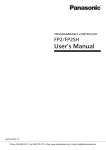
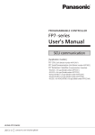
FP2 Multi-wire Link Unit (AFP2720)
Part Names and Functions
(1)Operation monitor LEDs
Indicates communication status and operation mode, such as run/stop, error/alarm..
(2)Station number selector
Sets the unit No. of the master unit in the network. (It is used in the W/W2 mode only.)
In the W mode, the setting will be effective as soon as a unit number is changed.In the W2 mode, unit
numbers should be changed when the power supply is off.The setting will be effective next time the
power turns on.
(3)Station number selector
Switches the display range of the station number LEDs. (It is used in the F mode only.)
(4)Mode selector switches (1)
Sets the operation mode (PC link mode, non-PC link mode, terminal station).
The setting of the mode selector switches should be changed when the power supply is off.The setting
will be effective next time the power turns on. (The setting for the terminal station will be effective as
soon as a unit number is changed.)
2-2
(5)RS485 interface
For connecting the communication cables.
(6)Fixing hooks
For installing the unit on the backplane for FP2.
(7)Mode selector switches (2)
Sets the operation mode (W/W2/F mode, baud rate).
The setting of the mode selector switches should be changed when the power supply is off.The setting
will be effective next time the power turns on.
(8)Connector for connecting to a backplane
Connects the unit to a slot on the backplane for FP2.
(9)Mounting screw
For attaching the unit to the backplane.
(10)Temporary joint hook
For attaching the unit to the backplane temporarily.
2-3
Operation monitor LEDs
:Lights:
LED
:Flashing
(T = 0.2 s),
Descrip
Operation
tion
W mode
Communicati
on status
:Flashing slowly (T = 1.0 s),
W2 mode
:Communicating
(Normal)
:Communicating
(Normal)
:Communication error
(Transmission is not
available)
:Out of control/Selfdiagnostic
Error
:Wait for starting error
(Note1)
:Various errors
(Note2)
:Normal operation
:Communication
buffer Overload
:Communication
error (Transmission
is not available)
:Out of control/
Self-diagnostic
Error
:Wait for starting
error (Note1)
:Various errors
(Note2)
:Normal operation
COM.
Hardware/
Software
error
ERR.
:Goes out:
F mode
:Waiting for
communication
:Communicating
(Normal)
:Stop mode
Transmitting
:Communication
error
:Out of control/
Self-diagnostic
Error
Setup error
:Normal operation
W
W mode
:In W mode
:Not in W mode
:Not in W mode
W2
W2 mode
:Not in W2 mode
:In W2 mode
:Not in W2 mode
F
F mode
:No in F mode
:No in F mode
:In F mode
:PC link operation
State
PC-L
PC link flag
(Available in
W/W2 mode
only)
:PC link operation
state
:PC link Operation
impossible
:Non-PC link
operation State
HI
TERM.
1/17~
8/24
9/25~16/
32
Baud rate
:PC link stop/
Non-PC link
operation State
:500 kbps fixed
:Not used
:500 kbps
:500 kbps fixed
:250 kbps
Terminal
station
Slave station
display
(Availalbe in
F mode only)
:Terminal station
:Not terminal station
:Connected
:Not connected
:Not used
* Slave station numbers
are switched by the
slave station number
selector.
Note1) It occurs when the version of CPU unit is Ver. 1.05 or older.
Note2) It occurs in case of transmission errors, when a station number is out of range, station numbers
are duplicated, or allocated link areas are duplicated.
Station number selector
Swithces the display range of the station number display.It is used in the F mode only.
Item
Setting
1-16
17-32
2-4
Indicates the monitor LEDs between the slave station
number 1 to 16.
Indicates the monitor LEDs between the slave station
number 17 to 32.
Station number selector
Sets the station number of the master unit in the W/W2 mode.It is not used in the F mode.
Operation Setting
01 to 32: Available
W mode
Other numbers: The station number setting error occurs.
(Changing station numbers in operation is possible.)
W2 mode
01 to 64: Available
Other numbers: The station number setting error occurs.
(Changing station numbers in operation is possible.)
Point the arrow to the number to be used.
Mode selector switches
Setting
Operation
mode
Not used
Terminal
station
setting
The swithces are all
set to the OFF
position at the
factory.
Operation
W mode W2 mode
SW
OFF
PC link mode
ON
Non-PC link mode
2
3
4
5
6
7
―
―
―
―
―
7: ON, 8: ON
―
―
―
―
―
Terminal station
8
7: OFF, 8: OFF
Not terminal station
1
F mode
The operation of the
master unit stops when
communication error
occurs.
The operation of the
master unit continues
when communication
error occurs.
W mode
W2 mode
F mode
Operatio 1
OFF
ON
ON
n mode
2
OFF
OFF
ON
Baud
OFF
500 kbps
500 kbps
500 kbps fixed
3
rate
fixed
250 kbps
ON
Note2)
―
4
Always set the switches to the OFF position.
Note1) The setting of the mode selector switches is reflected in the operation
monitor LEDs.
Note2) In the W2 mode, a unit at 500 kbps and a unit at 250 kbps cannot be
mixed in the same network.
Note3) Be sure the power is off when changing the selector position (except the
terminal station setting).
2-5
2.2 Remote I/O master unit
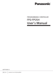
2.2.1 FP3 Remote I/O Master Unit (AFP3742)
Functions of each part
(1)Station number LEDs ………...
The LEDs indicating the slave station numbers (No. 1 to
No. 32) which are connected to the network light up.
Check the lighting-up by swiching the display range of the
station number LEDs between number 1 to 16 and number
17 to 32 with "Station number selector".
(2)Operation monitor LEDs …...
Indicates communication status and operation mode.
(3)Station number selector …...
Switches the display range of teh station number LEDs.
Refer to the description of "Station numbers LEDs" above.
2-6
(4)Mode selector switches
……
For selecting the transmission line, setting the terminal station and
selecting the mode when a tranmission error occurs.
SW
1、2
3、4
5、6
7
Setting
Port selection
Terminal station
setting
(Port I)
Terminal station
setting
(Port I)
OFF
Port I
ON
Port I and Port II
Not terminal
station
Terminal station
Not terminal
station
Terminal station
Master Unit
Continue the
operation
* The settings of SW1 and SW2, SW3 and SW4, and SW5 and SW6
should be same.
* The swithces are all set to the OFF position at the factory.SW8 is
not used.
* The settings will be accepted when the power turns on.
Condition during a
communication error
Master Unit
Stop the operation
⑤RS485 interface …...
For connecting the communication cables.Two poarts are available.
⑥Mounting screw ……
Connector
Connects the master unit to a slot on the backplane.
2-7
2.3 Remote I/O Slave Unit
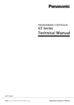
2.3.1 FP2 Remote I/O Slave Unit (AFP2745)
(1)Operation monitor LEDs
Name
COMM.
ALARM
TERM.
2-8
Display
Displays communication
: Waiting
status.
: Communicating (Normal)
: Lights
: Communicating (Stop mode)
: Flashing (T = 0.2 s),
: Flashing slowly (T = 1.0 s), : Communication error
: Goes out
Indicates an error on the unit.
: Unit error
: Lights
: Flashing quickly (T = 0.2 s), : Setting error
: Normal operation
: Goes out
Indicates the setting of termination resistance.
: Lights
: Termination resistance is on.
: Goes out
: Termination resistance is off.
Switches
Note) Be sure the power is off when changing the switches.
(2)Station number selector
Sets the station number of teh remote I/O slave unit.
Setting
01 to 32: Available
Other numbers: The station number setting error occurs.
Note) Setting error: The ALARM LED blinks.
(3)Termination resistance selector switch
ON
Termination resistance: ON
OFF
Termination resistance: OFF
(4)Mode selector switches
SW No.
Function
ON
Output condition during Maintains its output
a communication error
condition
2
Not used
3
Not used
4
Not used
5
Not used
6
Not used
7
Not used
8
Not used
Note) Set the unused swithces to the off position.
1
OFF
Output off
(5)RS485 interface
(6)Fixing hooks
(7)Connector for connecting to a backplane
(8)Mounting screw
(9)Temporary joint hook
2-9
2.3.2 FP3 Remote I/O Slave Unit (AFP3745)
Functions of each part
(1)Operation monitor LEDs ……
(2)Station number selector switches..
2-10
Indicates communication status and operation mode.
Set the station number of the MEWNET-F.Point the arrow
to the number to be used. (Set tens place and ones place
separately.)
Setting range: 01 to 32
* When setting numbers exceeding the range, the setup
error occurs (ALARM LED flashes), and communication
becomes impossible.
* The settings will be accepted when the power turns on.
Sets the terminal station and the output mode a communication
error occurs.
(3)Mode selector switches….
SW
1、2
Setting
OFF
Terminal station setting
Not terminal
station
ON
Terminal station
Maintains its output
Output condition during
Output off
condition
a communication error
* The settings of SW1 and SW2 should be the same.
* The swithces are all set to the OFF position at the factory.SW4 is not
used.
* The settings will be accepted when the power turns on.
3
(4)RS485 interface …...
For connecting the communication cables.
(5)Mounting screw ……….
Connector
Connects the slave unit to a CPU slot on the backplane.
2-11
2.4 I/O Terminal Board
FP I/O terminal baord [MIL connector type]
(AFP87445, AFP87446)
FP I/O terminal baord [Terminal block type] (AFP87444, AFP87432)
2-12
Functions of each part
(1)Operation monitor LEDs ..
Indicates communication status and operation mode.
Set the station number of the MEWNET-F.Point the arrow to the
number to be used. (Set tens place and ones place separately.)
Setting range: 01 to 32
* When setting numbers exceeding the range, the setup error occurs
(ALARM LED flashes), and communication becomes impossible.
* The settings will be accepted when the power turns on.
(2)Station number selector
switches (Rotary switches)
Sets the terminal station and the output mode a communication
error occurs.
(3)Mode selector switches ……
SW
1、2
3
(4)RS485 interface …...
Setting
Terminal station setting
OFF
Not terminal
station
ON
Terminal station
Maintains its
Output condition during a
Output off
output condition
communication error
* The settings of SW1 and SW2 should be the same.
* The swithces are all set to the OFF position at the factory.SW4 is
not used.
* The settings will be accepted when the power turns on.
For connecting the communication cables.
(5)Input terminals, Output terminals …
16-point input terimnals and 16-point outut terminals
(8 points for AFP87432). Including the power supply
terminal for an external device.
(6)Power supply terminal………….
Supply the power to activate the I/O terminal board.
(7)I/O monitor LEDs ….………....
Lights up when input or output is ON.Lights off when input
or outout is OFF.
For the information on the specifications and connections of hte I/O terminals and
power supply terminal, refer to the next page.
2-13
2.4.1 I/O Terminal Board Terminals Specifications
MIL connector type
Terminal layout diagrams
- Operating power supply voltage 12V DC type
(AFP87445)
- Operating power supply voltage 24V DC type
(AFP87446)
Note:
- Use the power supply cable (APL9511) attached to the I/O terminal board [MIL connector type] for the
power supply.
* The power supply input termial for I/O and the 12 V (+) or 24 V (+) terminals are internally
connected.The supplied power is used to drive transistors of internal circuit.
* The spare power input terminal and spare output terminals are internally connected.When supplying
DC power (5 V to 24 V) at the power supply terminal, you can used the power to operate an input device
connected to an input terminal.
- N. C. means Not Connected.These terminals are not connected internally.
2-14
Connection example
Input circuit and external connections
- When power is not supplied through the I/O
power supply terminal
- When power is supplied through the I/O
power supply terminal
Output circuit and external connections
- When power is not supplied through the I/O
power supply input terminal
- When power is supplied through the I/O
power supply input terminal
Note:
- When using a limit switch with an LED as the input device, be sure that the internal resistance is 15 kΩ
(SL, QL, VL type)
- The (+) side in the diagrams is DC +12 V for AFP87445, and DC +24 V for AFP87446.
2-15
Terminal block type
Terminal layout diagrams
- Transistor output type (AFP87444)
- Relay output type (AFP87432)
Note:
- The terminal screws for the I/O terminals and power supply terminal are all M3.
- N. C. means Not Connected.These terminals are not connected internally.
- Supply power for internal transistors or relays to pins 17 and 18.
2-16
Connection example
Input circuit and external connections
- Common to Transistor output type (AFP(87444) and Relay output type (AFP87432)
Output circuit and external connections
- Transistor output type (AFP87444)
- Relay output type (AFP87432)
Note:
- When using a limit switch with an LED as the input device, be sure that the internal resistance is 15 kΩ
(SL, QL, VL type)
2-17
2.5 I/O Terminal Unit
I/O terminal unit (Primary unit)
8-point input (AFP87421) 8-point input (AFP87423)
16-point input (AFP87422) 16-point input (AFP87424)
Expansion I/O terminal unit
8-point input (AFP87425) 8-point input (AFP87427)
16-point input (AFP87426) 16-point input (AFP87428)
2-18
Functions of each part
(1)Operation monitor LEDs ..
Indicates communication status and operation mode.
Set the station number of the MEWNET-F.Point the arrow to the
number to be used. (Set tens place and ones place separately.)
Setting range: 01 to 32
* When setting numbers exceeding the range, the setup error occurs
(ALARM LED flashes), and communication becomes impossible.
* The settings will be accepted when the power turns on.
(2)Station number selector
switches (Rotary switches)
Sets the terminal station and the output mode a communication
error occurs.
(3)Mode selector switches ……
SW
Setting
1、2
ON
Terminal station
Maintains its
Output condition during
Output off
output condition
a communication error
* The settings of SW1 and SW2 should be the same.
* The swithces are all set to the OFF position at the factory.SW4 is
not used.
* The settings will be accepted when the power turns on.
3
(4)RS485 interface …...
Terminal station setting
OFF
Not terminal
station
For connecting the communication cables.
(5)Input terminals, Output terminals …
They are configured with 8-point input/output terminals
or 16-point input/output terminals.
(6)Power supply terminal………….
Supply the power to activate the I/O terminal board.
(7)I/O monitor LEDs ….………....
Lights up when input or output is ON.Lights off when input
or outout is OFF.
(8)Expansion connector….…
Connects the primary I/O terminal unit and the expansion I/O
terminal unit with a cable.
Use a PL Mark expansion cable (APL2510, APL2511 or APL2515).
For the information on the specifications and connections of hte I/O terminals and
power supply terminal, refer to the next page.
2-19
2.5.1 I/O Terminal Unit Terminals Specifications
Input unit
Terminal layout diagrams
- 16-point type Primary unit (AFP87422)
Expansion unit (AFP87426)
- 8-point type Primary unit (AFP87421)
Expansion unit (AFP87425)
- In case of expansion unit, the terminals of the
RS485 interface (pins 20 and 21 for the 8-point
unit, pins 36 and 37 for the 16-point unit) is N.C.
(Not connected) terminals.These terminals are not
connected internally.
Note:
- Power supply input (24 V) terminal and all (+) terminals are internally connected. Power supply input (0
V) terminal and all (-) terminals are internally connected.When using (+) or (-) terminal as a common
terminal, use the one closest to the output terminal.
- The screw terminals are all M3.5.
Note:
- When using a limit switch with an LED as the input device, be sure that the internal resistance is 15 kΩ
(SL, QL, VL type)
- Precautions when using an external power supply
- Use an external power supply at 26.4 V DC or less. (It does not work with the power supply for
operating.)
- When using an external power supply at a low voltage, the current may flow to the external power
supply from the 24 V DC for operating even if it is off. Therefore, the leak current should be 1 mA or less
when it is off.
2-20
Output unit
Terminal layout diagrams
- 16-point type Primary unit (AFP87424)
Expansion unit (AFP87428)
- 8-point type Primary unit (AFP87423)
Expansion unit (AFP87427)
- In case of expansion unit, the terminals of
the RS485 interface (pins 20 and 21 for the 8point unit, pins 36 and 37 for the 16-point unit)
is N.C. (Not connected) terminals.These
terminals are not connected internally.
Note:
- Power supply input (24 V) terminal and all (+) terminals are internally connected. Power supply input (0
V) terminal and all (-) terminals are internally connected.When using (+) or (-) terminal as a common
terminal, use the one closest to the output terminal.
- The screw terminals are all M3.5.
Note:Precautions when using an external power supply
- Use an external power supply in the range of 20.4 V DC to 26.4 V DC.(It does not work with the power
supply for operating.)
- Up to 16 points can be used with the power supply of 0.5 A. (All the points can be simultaneously
turend on.)However, in this case, use the (-) terminal that is close to the output terminal to be used.
2-21
2-22
Chapter 3
Unit Specifications
3.1 General Specifications (Common to the System)
Item
Ambient temperature
Storage temperature
Ambient humidity
Storage humidity
Vibration resistance
Shock resistance
Noise immunity
Operating condition
3-2
Specifications
0~55℃
-20~70℃
30 to 85 % RH (at 25℃, non-condensing)
30 to 85 % RH (at 25℃, non-condensing)
10 to 55 Hz, 1 cycle/min.
double amplitude of 0.75 mm, 10 min. on 3 axes
Shock of 98 m/s2 , 4 times on 3 axes
1000 V[p-p] with pulse widths of 50 ns or 1µs (based on in-house
measurements)
Free from corrosive gases and excessive dust
3.2 Performance Specifications (Common to the System)
Item
Specifications
Communication method
Synchronous method
Transmission distance Note1)
Baud rate
Transmission line
Interface
Transmission error check
No. of master units
per 1 CPU
No. of slave stations per
1 master unit
Two-wire, half duplex transmission
Start stop synchronous system
700 m (total length) per 1 port (2 paths)
0.5 M bps
2
2-wire cable (VCTF0.75 mm x 2C (JIS) or equivalent) is used
Multi-drop (RS485)
CRC (Cyclic Redundancy Check) method
No. of I/O points for
each station
Max. 32 stations
Max. 2048 points (FP2/FP3)
Max. 4096 points (FP2SH/FP10SH)
For FP3 Master unit Ver. 1.4 or older, max. 1024 poins
I/O Terminal
Board
32 points per unit (16-point input + 16-point output) or
24 points (Input: 16 points + Output: 8 point)
* I/O numbers are allocated from the input side.
I/O Terminal
Unit
Per unit, when using a single unit: 16 points, when using expansion units: 32
points
* Number of occupied points is the same for the 8-point unit and 16-point unit.
When combining the input and output, I/O numbers are allocated from the input
side, which are 16-point input and 16-point output.
Per 1 CPU
Per 1 master unit
FP2/FP3
Slave station
system
No. of slots for each
station
No. of controllable I/O points
No. of controllable slots
I/O control
Per 1 master unit
Max. 4 units
Max. 128 slots
Max. 64 slots
Max. 24 slots
I/O Terminal
Board
1 slot
I/O Terminal
Unit
1 slot
* Number of slot is 1 even if a unit is added.
FP3
Units that cannot be installed
on the backplane of slave
station system
FP2
Master Unit, MEWNET-P/W/H Link Unit
ET-LAN Unit, Computer Communication Unit (CCU),
C-NET Link Unit, S-LINK Unit
Advanced units that occur interrupt
Multi-wire Link Unit, MEWNET-VE Link Unit
ET-LAN Unit, Computer Communication Unit (CCU),
Multi Communication Unit
A/D Unit, D/A Unit, RTD Unit
Positioning Unit RTEX
Positioning Unit Interpolation type
Positioning Unit Multifunction type
Advanced units that occur interrupt
Note1) The transmission distance varies according to the used cable and type of unit.
Note2) The advanced units that occur interrupt are as follows. - Interrupt unit
- High-speed counter unit and Pulse output unit can be used when setting to the mode that does
not occur interrupt.
- As there is no indication for the error that a prohibited unit is installed on FP2 A/D unit, D/A unit
and RTD unit, no error indication will be displayed, even If they are installed incorrectly.
Note3) When using a positioning unit for FP2 slave station system, and If the time taken from the startup to the completion of positioning operation is shorter than the scan time, flags such as the
output end flag and pulse output flag may not be read and an error may occur.The time from the
start-up to the completion of positioning operation must be longer than the scan time.
Note4) When using a S-LINK unit for FP2 slave station system, the settings of I/O points including 96
input points and 96 output points cannot be used.
3-3
3.3 Rating and Specifications of Components
3.3.1 Master Unit
Type
Consumption
current (5 V DC)
Weight
Power
supply
voltage
Model No.
Approx.
AFP2720
110 g
Approx.
AFP3742
FP3 Remote I/O Master Unit
450 mA or less
260g
Note) The consumption current is the value when the station number LEDs are all lights up.
FP2 Multi-wire Link Unit
220 mA or less
3.3.2 Slave Unit
Type
Consumption
current (5 V DC)
FP2 Remote I/OSlave Unit
150 mA or less
FP3 Remote I/OSlave Unit
400 mA or less
Weight
Approx.
110 g
Approx.
310g
Power
supply
voltage
Model No.
-
AFP2745
-
AFP3745
3.3.3 I/O Terminal Board
General specifications
Type
FP I/O Terminal Unit
[MIL connector type (12 V DC)]
FP I/O Terminal Board
[MIL connector type (24 V DC)]
FP I/O Terminal Board
[Terminal block type (Tr. output)]
FP I/O Terminal Board
[Terminal block type (Ry. output)]
3-4
Consumption
current
200 mA or
less
100 mA or
less
100 mA or
less
100 mA or
less
Weight
Approx.
470g
Approx.
470g
Approx.
520g
Approx.
540g
Power supply
voltage
10.2 V DC to 13.2 V
DC
20.4 V DC to 26.4 V
DC
20.4 V DC to 26.4 V
DC
20.4 V DC to 26.4 V
DC
Model No.
AFP87445
AFP87446
AFP87444
AFP87432
I/O Terminal Board I/O part specifications
-Input part (Common)
Item
Specifications
Type
AFP87445
Rated input voltage
12 V DC
Input impedance
Approx. 2 kΩ
Insulation method
Photocoupler
ON delay time
2 ms or less
OFF delay time
2 ms or less
Power supply voltage 10.2 V DC to 13.2 V DC
range
No. of circuits
16 points/common
ON voltage
8.6 V or less
OFF voltage
2.4 V or more
Common polarity
Positive (+) polarity
AFP87446, AFP87444, AFP87432
24 V DC
Approx. 4.4 kΩ
20.4 V DC to 26.4 V DC
19.2 V or less
-Output
Transistor output type (AFP87445, AFP87446, AFP87444)
Item
Specifications
Type
AFP87445
AFP87446, AFP87444
Rated output voltage
12 V DC
24 V DC
Insulation method
Photocoupler
ON delay time
1 ms or less
OFF delay time
1 ms or less
Power supply voltage
10.2 V DC to 13.2 V DC
20.4 V DC to 26.4 V DC
range
Max. control capacity
0.2 A/point
Leakage current
100µA or less
Residual voltage
1.5 V or less
No. of circuits
16 points/common
Output type
Transistor output (NPN open collector)
Common polarity
Positive (+) polarity
Relay output type (AFP87432)
Item
Type
Rated control capacity:
Insulation method
ON delay time
OFF delay time
Mechanical lifetime
Lifetime
Electrical lifetime
External power
Voltage
supply
Current
No. of circuits
Output type
Specifications
AFP87432
2A 250V AC , 2A 30 DC
Photocoupler
10 ms or less
10 ms or less
Min. 20,000,000 operations
Min. 100,000 operations
22.2 V DC to 26.4 V DC
100 mA or less
1 point/common x 8 points (independent common)
Relay output
3-5
3.3.4 I/O Terminal Unit
General specifications
Type
FP I/O Terminal Unit
(Input 8 points)
FP I/O Terminal Unit
(Input 16 points)
FP I/O Terminal Unit
(Output 8 points)
FP I/O Terminal Unit
(Output 16 points)
Expansion I/O terminal unit
(Input 8 points)
Expansion I/O terminal unit
(Input 16 points)
Expansion I/O terminal unit
(Output 8 points)
Expansion I/O terminal unit
(Output 16 points)
Consumption current (24 V DC)
When all
When all points
points are OFF are ON
0.1 A or less
0.04 A or less
Note1)
0.15 A or less
0.04 A or less
Note1)
0.1 A or less
0.04 A or less
Note2)
0.15 A or less
0.04 A or less
Note2)
0.06 A or less
Note1)
0.11 A or less
Note1)
0.06 A or less
Note2)
0.11 A or less
Note2)
Weight
Model No.
Approx. 200g
AFP87421
Approx. 280g
AFP87422
Approx. 200g
AFP87423
Approx. 280g
AFP87424
Approx. 170g
AFP87425
Approx. 270g
AFP87426
Approx. 170g
AFP87427
Approx. 270g
AFP87428
Note1) This is the value including the input curren when all points are ON.
Note2) Thi is the value with no load when all points are ON.
I/O part specifications
Input unit
Item
Type
Rated input voltage
Allowable input voltage
Input impedance
Insulation method
ON delay time
OFF delay time
No. of circuits
ON voltage
OFF voltage
Common polarity
3-6
Specifications
8-point input unit
24 V DC
20.4 V DC to 26.4 V DC
Approx. 4.4 kΩ
Photocoupler
2 ms or less
2 ms or less
8 points/common
19.2 V or less
2.4 V or more
Negative (-) polarity
16-point input unit
16 points/common
Output unit
Item
Specifications
Type
8-point output unit
16-point output unit
Rated output voltage
24 V DC
Allowable output voltage
20.4 V DC to 26.4 V DC
Insulation method
Photocoupler
ON delay time
1 ms or less
OFF delay time
1 ms or less
Max. control capacity
0.5 A/point, 1 A/common
Leakage current
100µA or less
Residual voltage
1.5 V or less
No. of circuits
8 points/common
16 points/common
Output type
Transistor output (NPN open collector)
Common polarity
Positive (+) polarity
Note) The input voltage and the output voltage is the same us the power supply voltage.
3-7
3.4 Transmission Cable Specifications
3.4.1 Recommended Cables
The cables in the table below are recommended for FP remote I/O system [MEWNET-F].The
guaranteed transmission distance vary according to the used cables.
Conductor
Insulator
Trans
missio
Cabl
Sample
Cable
Crossn
Resistan
Thic
e
appropria
Material
sectional view Size
distan
ce
knes
Note2)
diam.
te cable
ce
(at 20℃)
s
Note1)
2
1.25 mm
(AWG16)
or more
Shielded
twisted
pair
Polyethyl
ene
Max.
33.4 Ω/km
Polyethyl
ene
Max.
0.5
mm
Appro
x. 7.8
mm
600 m
(300 m)
Max.
25.1 Ω/km
Polyvinyl
chloride
Max.
0.6
mm
Appro
x. 6.6
mm
400 m
(200 m)
2
0.5 mm
(AWG20)
or more
VCTF
Max.
16.8 Ω/km
Max.
0.5
mm
0.75 mm2
(AWG18)
or more
Appro
x. 8.5
mm
700 m
(300 m)
Hitachi
Cable, Ltd.
KPEV-S1P x
1.25SQ
Belden
9860
Hitachi
Cable, Ltd.
KPEV-S1P
x 0.5SQ
Belden
9207
VCTF0.75
mm2 x 2C
(JIS)
Note1) When any of the product numbers AFP87441, AFP87442, AFP3741, AFP5741 and various
companies' valve controllers is contained in the network, the maximum transmission distance is
the values in parentheses.For the information on various companies' valve controllers, please
contact each company.
Note2) Polyvinyl chloride has worse electrical charactersitics than polyethylene, its transmission distance
is shorter.
Note3) Use only one type of transmission cable.Do not mix more than 1 type.
Note4) Twisted pair cables are recommended in noisy environments.
3-8
3.4.2 Terminals
Be sure to use crimp terminals for processing the end of transmission cables.
If connecting the cables directly to the terminal blocks without using crimp terminals, contact failures may
easily occur and normal communication may not be performed.
Suitable crimp
terminal
Manufacturer
JST Mfg. Co., Ltd.
1. Ring terminal
2. Insulated ring terminal
3. Fork terminal
Shape
Ring type
Model name
1.25-YS3A
Terminals for FP2 Multi-wire Link unit/FP2 Remote I/O Slave Unit
- Use M3 terminal screws for the terminal of FP2 Multi-wire Link Unit/FP2 Remote I/O Slave Unit.
Use the crimp temrinals having the following shapes.- Fasten the terminals securely applying a
tightening torque of 0.5 to 0.6 N m.
Example of suitable crimp terminal
Manufacturer
Shape
Model name
JST Mfg. Co., Ltd.
Fork type
2-MS3
Suitable wires (Copper strand wire)
- Size: AWG20-12, Rated temperature: 60/75 °C
Tightening torque: 0.5-0.6 N m (5.3 lb-in)
3-9
3.5 Communication Time
The communication time regarding the remote I/O system [MEWNET-F] control is described.
3.5.1 Remote I/O Scan Time [TR]
The remote I/O scan time represents the time it takes the master unit, with respect to the connected
slave stations, to send all the output data which has been written to the buffer memory in the master unit
and write all the input data received from the slave stations to the buffer memory in the master unit.
TR=0.8+0.85×n+0.55×N+0.13×W (ms)
n
N
W
: No. of I/O terminal boards
: No. of slave units
: No. of I/O words used by the remote I/O system
[Example]
When 10 FP I/O terminal boards (16 input points and 16 output points) and a salve station (connected to
one slave unit, 4 input units (32 input point), 4 output unit (32 output points)] are connected.
3.5.2 Remote I/O Memory Access Time [TRM]
The remote I/O memory access time represents the time it takes the master unit to receive the memory
access end message from the slave unit after it receives a memroy access request from the CPU.
As this value is a guide, confirm on the actual units.
[Example]
When 5 I/O terminal boards (16 input points and 16 output points each) and a slave station [connected
to 1 slave unit, 2 input units (32 input points), 2 output unit (32 output points) and 1 advanced unit
(occupies 32 points)] are connected and a 32-word memory access is performed with an advanced unit.
3-10
3.5.3 Input/Output Response Time for Remote I/O System [TRES]
The input/output response time for a remote I/O system represents the time it takes to send the input
signal from the slave station to teh CPU via the master unit and perform the processing, and the time
until the output signal is actually sent to teh slave station based on the processing result.
TRES=TIRES+TC+TORES
TRES
TIRES
TC
TORES
: Input/Output response time for Remote I/O system
: Input response time for Remote I/O system
: Output response time for Remote I/O system
: CPU scan time
The maximum values of input/output response time for the remote I/O system are obtained in the
following manner.
TRES・MAX=TIRES・MAX+TC+TORES・MAX
TIRES・MAX=TIDLY+TR+Tα
TIDLY
: Input delay time
: Scan time for remote I/O system
TR
: - When synchronous mode
Tα
- When TC<TR, Tα=TR
- When TC>TR, Tα=TC
- When asynchronous mode
- When TC<TR, Tα=TC+TR
- When TC>TR, Tα=TC
TORES・MAX=TR×2+TODLY
Reference: For information on the synchronous mode and asynchronous mode,
<7.4 Remote I/O Update Timing Method"
3-11
3-12
Chapter 4
Installation and Wiring
4.1 Preparation of MEWNET-F Components
Prepare each stations that configures the remote I/O system [MEWNET-F].The system configuration and
the condition and method of installation is described.
4.1.1 Master Station (Master Unit)
A master station can be configured with a "remote I/O master unit" installed on the FP2/FP2SH or
FP3/FP10SH system.Up to 4 units can be installed to one CPU unit.
Installation condition
A master unit can be installed in any I/O slot on a mater backplane or expansion backplane.
Up to 4 units can be installed.
The conditions of system configuration (such as number of expansion, restrictions on power supply and
total length) are the same as the normal case.
4-2
Installation method
Be sure to remove or install units only when all power is off.
Do not touch the terminals of connectors cirectly.It may cause contact failures or the damage to
elements due to static electricity/
FP3/FP10SH
1. Fit the unit tabs into the unit holes on teh backplane.
2. Push the unit in the direction of the arrow to plug it into the backplane.
3. After properly plugging the unit into the backplane, tighten the installing screw at the top.
Reference: For FP2/FP2SH, <FP2/FP2SH Hardware Manual ARCT1F320E>
4-3
4.1.2 Slave Station System (Slave Unit)
When installing a "FP2 Remote I/O Slave Unit" or "FP3 Remote I/O Slave Unit" instead of a CPU, the
slave station with the slave unit is controlled by the CPU on the master station.
Installation condition
- Install a slave unit in the CPU slot position of the master backplane.
- With FP2 backplane H type
When using a 1-module type power supply unit, a space of 1 module will be created between a slave
station and the power supply unit. In this case, do not install a wiring line in this space.
- In the I/O slots, you can install input units, output units or advanced units which are controlled by the
CPU from the master station. (For information on the installing method, refer to the case of a master
unit in the previous page.)Note that some advanced units cannot be installed.
- Up to 3 backplanes including a master backplane can be added. Use expansion cables following the
restriction described in the table below. Other conditions of system configuration such as restrictions on
power are the same as the normal case.
[Example: FP3 Slave station system]
Restrictions on the expansion with slave stations
Backplane type
No. of connected boards
Standard type
Max. 1 board
H type
Max. 2 boards
2.6 m or less in total
Max. 2 boards
AFP3510 (50cm)
AFP3511 (1m)
FP2
FP3
Expansion cable
AFP2510(0.6m)
AFP2512(2m)
Reference: For information on the advanced units that cannot be installed,
<3.2 Performance Specifications>
4-4
Installation method
- Be sure to remove or install units only when all power is off.
- Do not touch the terminals of connectors cirectly.It may cause contact failures or the damage to
elements due to static electricity/
FP3
1. Fit the unit tabs into the unit holes on teh backplane.
2. Push the unit in the direction of the arrow to plug it into the backplane.
3. After properly plugging the unit into the backplane, tighten the installing screw at the top and bottom.
Reference: For FP2/FP2SH, <FP2/FP2SH Hardware Manual ARCT1F320E>
4-5
4.1.3 I/O Terminal Board (Slave Station)
"FP I/O Terminal Board" is an exclusive I/O terminal for the remote I/O system [MEWNET-F] that can be
controlled as "Slave station" with the CPU on the master station.One unit configure one station, and no
restriction on the usable number of units if it is within the number of total slave stations.The MIL
connector type and the terminal block type are available.
Installation method
- To install a unit on DIN reails, use the DIN rail mounting hook which is attached to the mounting plate.
Note:
Avoid using rail mounting in locations with sever vibrations and shock. Mount directly to the panel with
screws.
Installation
Align it with the mounting rail groove and push it down to install it.
Removal
To detach a unit from the DIN rail, pull the hook down with a slotted screwdriver.
Reference: For information on the mounting hole dimensions, <Chapter 10 Dimensions>
4-6
4.1.4 I/O Terminal Unit (Slave Station)
"FP I/O Terminal Unit" is an exclusive I/O terminal for the remote I/O system [MEWNET-F] that can be
controlled as "Slave station" with the CPU on the master station.One unit configure one station, and no
restriction on the usable number of units if it is within the number of total slave stations.
Also, I/O can be configured if necessary by connecting expansion units.
Expansion of I/O terminal unit
Only one expansion unit can be connected to one master unit.(Up to two connections are possible.More
than three connections are not possible.)
The input or output, and 8 points or 16 points can be freely selected and combined.
An expansion unit has two expansion connectors.Use only any one to connect the unit to the master unit.
Use a PLC Mark II expansion cable to connect an expansion unit to a master unit. (A 8-cm cable is
attached to an expansion unit as a standard accessory.)
Installation method
To install a unit on DIN reails, use the DIN rail mounting lever which is attached to the mounting plate of
I/O terminal board.
Note:
Avoid using rail mounting in locations with sever vibrations and shock. Mount directly to the panel with
screws.
Installation
Align it with the mounting rail groove and push it down to install it.
Removal
To detach a unit from the DIN rail, pull the hook down with a slotted screwdriver.
Reference: For information on the mounting hole dimensions, <Chapter 10 Dimensions>
4-7
4.1.5 Reference (Check Flow Chart>
The flowchart for checking whether or not each station that is confgured meets the system specifications.
1) First, check the slave stations connected to the same master unit. Check the slave stations for each
master unit.
2) Check the remote I/O system controlled by one CPU.
4-8
4.2 Power Up Sequence
The procedure for starting the remote I/O system [MEWNET-F] is as follows.
1. Power up all the remote I/O controlled slave stations.
↓
2. Power up the master station system (i.e. the system that the master unit is connected). (The remote
I/O control will be performed for the running slave stations at this point.)
↓
3. Set the CPU of the master station system to "RUN mode".
The basic procedure is as above, however, the procedure after the start-up may be different according to
the settings.
4.2.1 Remote I/O Mapping, Slave Station Connection Confirmation Mode
If a slave station registered in the remote I/O map has not been turned on, the operation will not start
until the slave station is turned on although the master station system has been turned on and set in
"RUN mode" (The PROG. LED of the CPU is blinking during confirmation). The remote I/O control will
be perfomred when setting to "RUN mode", if the master station system is turned on after all the
registered slave stations have been turned on.
Reference: <7.3 Slave Station Connection Confirmation Mode>
4.2.2 Remote I/O Mapping, Slave Station Connection Not Confirmed Mode
Remote I/O control is performed only for the slave stations which have been already turned on when the
master station system turns on (3).
Even if there is a slave station which is not activated when the master unit is turned on, if it has been
registered in the remote I/O map, it will be controlled by the master unit after it powers up.
Reference: <6.2 Automatic I/O Number Allocation and Arbitrary I/O Number Allocation>
4.2.3 Remote I/O Map Not Registered Mode
Remote I/O control is performed only for the slave stations which have been already turned on when the
master station system turns on (2). (Automatic allocation)
If you turn on the slave stations after turning on the master unit, the CPU on the master station will not
be able to control the slave stations. You may not allocate I/O numbers in sequence.
Be sure to trun on the salve stations to be controlled first, then turn on the master station.
Turn on the master station system after turning on all the salve stations.
Reference: <6.2 Automatic I/O Number Allocation and Arbitrary I/O Number Allocation>
When actually controlling devices, it is recommended to register an remote I/O map.
4-9
4-10
Chapter 5
Connection for the Remote I/O System
5.1 Connection for the Remote I/O System
This chapter explains the connection and setting procedure for the remote I/O system [MEWNET-F].
The connection and setting is performed according to the connection pattern or operation.Note the
followings when connecting the remote I/O system.
-Connection patter, station number of slave stations
-Remote I/O map
-Process when an error occurs
-Timing of remote I/O update
-Programming tool to be used for remote programming
5.1.1 Description of Connection and Setting Procedure
5-2
5.2 Connection Pattern for MEWNET-F
There are following 6 types (A to F) of patterns for connecting the master station (master unit) and slave
stations (such as slave units and FP I/O terminal).For the FP2 Multi-wire Link Unit, only the connection
patterns A and B are available.
Note:
- Do not perform the connections other than the following 6 types.
- Do not perform star-burst connection.
- In the diagram below, each station is described as follows.
○ Connection port
● Connection port (for a terminal station)
<Slave station>
<Master station>
* On a terminal station, turn on the
terminal station setting switch.
5.2.1 Connection Pattern A
1 transmission line (using port I only), 1 path
- The terminal station is the master unit (port 1) and the slave station at the end.
- The connection using the port II only is not possible.
Note) FP2 Multi-wire Unit has the port I only.
5.2.2 Connection Pattern B
1 transmission line (using port I only), 2 paths
- The terminal stations are the slave stations at the both ends of each paths.
- The connection using the port II only is not possible.
Note) FP2 Multi-wire Unit has the port I only.
5.2.3 Connection Pattern C
2 transmission lines (using port I and port II), 1 path each
- The terminal station is the master unit (ports I and II) and the slave station at the end of each
transmission line.
Note) FP2 Multi-wire Unit has the port I only.
5-3
5.2.4 Connection Pattern D
2 transmission lines (using port I and port II), 2 path each
- The terminal stations are the slave stations at the both ends of each transmission line.
Note) FP2 Multi-wire Unit has the port I only.
5.2.5 Connection Pattern E
2 transmission lines (using port I and port II), 1 path for the port I, 2 paths for the port II
- When using the port I, the terminal station is the master unit and the slave station at the end. When
using the port II, the terminal stations are the slave stations at the both ends of transmission lines
Note) FP2 Multi-wire Unit has the port I only.
5.2.6 Connection Pattern F
2 transmission lines (using port I and port II), 2 paths for the port I, 1 path for the port II
- When using the port I, the terminal stations are the slave stations at the both ends of transmission lines.
When using the port II, the terminal station is the master unit and the slave station at the end.
Note) FP2 Multi-wire Unit has the port I only.
5-4
5.3 Procedure for Connecting and Setting Up
The connection and setting procedure of teh remote I/O system [MEWNET-F] is described as follows.
5.3.1 Preparation
Turn OFF all power supply to devices.
Configure the master stations and slave stations.This section describes an example of the procedure
using the following 4 stations.
Install each station at prescribed positions.
Configure a system which perform the remote I/O control with a master unit, 3 stations, 5 slots and 128
I/O points.
This CPU controls the normal I/O area and remote I/O area with totally 8 slots and 176 I/O points.
Reference: For information on the onstallation of master station system and slave station system,
<FP3/FP10SH/FP10S Hardware Manual ARCT1F300E-1>
Master Station (Master Unit)
Slave station
Max. 4 units/1 CPU
Per 1 master unit (1 path)
- Max. 32 stations
- Max. 64 slots
Per 1 CPU
- Max. 128 slots
Note:
If the system is not properly configured, an error will be detected when the power turned on.
[E35] There are units which cannot be installed on a slave station system.
[E36] Number of slots or number of I/O points is out of range.
5-5
5.3.2 Precedure 1 Wiring of Transmission Cables
Connect each station with transmission cables (2-wire cables).
For transmission cables, use a twisted pair cable or VCTF 0.75 mm2 x 2C (JIS) or equivalent.
The length of transmission cables should not be longer than the maximum transmission distance
(from a temrinal station to a terminal station) for each transmission line.
Connection method
1. Connection and wiring should be carried out from the master unit.
2. Wiring should extend from one unit to the next.Never run two wires from a single unit to two other
units.
3. When connecting the RS485 interface of each station, be sure to connect positive (+) to positive, and
negative (-) to negative. (Refer to the figure below.)
4. Connect one end of the shielded line of the transmission cable to the F.G. terminal, and ground it.
(Refer to the figure.)
Example of wiring
The left figure is the "Connection pattern
B".When connecting one transmission line,
use the port I for the master unit.
Reference: For information on the maximum transmission distance,
<3.4 Transmission Cable Specifications>
5-6
5.3.3 Procedure 2 Master Station (Master Unit) Setting
Set the master unit.
Note) The setting for FP2 Multi-wire Link Unit is different.
Reference: <FP2 Multi-wire Link Unit ARCT1F284 2.2>
Selecting a transmission port (transmission line)
Select a transmission port to be used and make the setting.Set the mode selector siwthces "SW3 &
SW4"
Set the mode selector switches "SW1 & SW2" to OFF as
connection example.
Configuring a terminal station
When a slave unit is located at the end of a transmission line, the unit must be configured as a terminal
station.
Setting method
Set the mode selector siwthces "SW3 & SW4".
Set the mode selector switches "SW3 & SW4 to OFF as
connection example.
If the terminal stations are not properly configured, the
ERROR LED on the CPU will be turned on when the power is
turned on.(Self-diagnostic error code E51).Turn on the power
again after making the correnct setting.
Selecting an operation mode during a communication error
Select whether to stop or continue the MEWNET-F control configured by this master unit when a
communication error occurs.Set the mode selector switch "SW7".
Reference:
The operation mode when a communication error occurs is related to the setting for the CPU of the
master station.
For the details of operation status, <7.2 Remote I/O Control When an Error Occurs"
5-7
5.3.4 Procedure 3 Slave Station Setting
Set slave stations (such as a system which a slave unit is installed, I/O terminal board and I/O terminal
unit).
Setting the slave station number
Note the followings when setting the station numbers for slave stations.
Up to 32 stations can be connected to one master unit (station number range: 01 to 32).However, the
total number of I/O points should not be more than 1024 points.
Do not use the same station number as the other slave stations connected to the same master unit.(The
same station number can be used when the connected master unit is different.)
I/O numbers are allocated from the smallest station number in ascending order.
Note) If any number other than 01 to 32, an error will occur and the remote I/O control cannot be
performed.When a setting error occurs, the ALARM LED on the slave station flashes.
Setting method
Set the station numbers with the station number selectors (rotary swithces).
Note1) The station numbers are not necessarily set in the order of connection.
Note2) It is no matter if there are blank station numbers.
Setting example
Set the slave station (A) indicated in "Procedure 1" to the slave station number 1,
set the slave station (B) to the slave station number 3,
set the slave station (C) to the slave station number 4.
The I/O numbers are allocated for (A), (B) and (C) in that order.Refer to "Procedure 4" for information on
the I/O numbers.
Reference:
For the details of manifold solenoid valves manufactured by various campanies, also refer to respective
manuals.
For information on the allocation of I/O numbers, <Chapter 6 Remote I/O Map>
Note:
Do not rotate the station number selectors after turning on the power supply.
Changing the station numbers will not affect in operaiton as the control is performed with the station
numbers when the power turned on, however, it will cause an error in the next startup.
5-8
Configuring a terminal station
When a slave unit is located at the end of a transmission line, the unit must be configured as a terminal
station.
In the example described in "Procedure 1", the slave stations (A) and (C) are the terminal stations.
Setting method
Set the mode selector siwthces "SW1 & SW2".
If the terminal stations are not properly configured, the
ERROR LED on the CPU will be turned on when the
power is turned on.(Self-diagnostic error code
E51).Turn on the power again after making the correnct
setting.
Setting example
For the slave station which is not a terminal station, set
the mode selector switches "SW1 & SW2" to OFF.
Setting the output status during a communication error
The operation status of the slave unit when a communication error occurs is selected whether to turn
"OFF" or "Hold" the output operation with the mode selector switch "SW3".
5-9
5.3.5 Procedure 4 Power Up Sequence
Turn on the power to the system after completing the installation of the master and slave stations, wiring
with transmission cables and settings of station numbers and terminal stations.
Once the power turns one, the remote I/O control will be enalbed, and the operation can be confirmed.
(The settings on the CPU such as the I/O number allocation are available.)
Confirming the power up and remote I/O control
Procedure
1. Power up the remote I/O controlled slave stations.
2. Set the CPU on the master unit to PROG. mode.
3. Power up the master station system as the last step.
Note1) When you power up the master station, the COMM. LED (COM. LED) of all teh stations will flash
quickly.Please confirm.
Note2) When teh PROG. LED on the CPU is flashing, the remote I/O map may be already registered.
Confirmation
When a remote I/O map has not been registered in the CPU, I/O numbers are allocated automatically
only for the slave stations which have been turned on. (This is called the remote I/O control using
"Automatic allocation".)
(1)When starting up the system in the above procedure, the I/O number allocation using "Automatic
allocation" is as follows in the "Procedure 1" example.
-The left example is a case that
various settings such as I/O map and
base word number are the default
values.
-Master station: Master 1
Base word number: 64
* The starting number for the I/O
numbers of slave stations in the
master 1 system is 640.
(2) The operation turning on/off the I/O of each station can be confirmed by writing a sequence program
to the CPU of the master station or performing forced input/output.
Reference: <Chapter 6 Remote I/O Map>, <7.3 Slave Station Connection Confirmation Mode>
5-10
Assigning and registering remote I/O numbers
A remote I/O map (I/O numbers which are allocated for the remote I/O system [MEWNET-F]) can be
registered in the CPU.
If regsitering a remote I/O map,
-Even if there is a slave station which is not activated when the master unit is turned on, the remote I/O
map (remote I/O number allocation) will not be changed.
It is possible to wait to execute a program until all slave stations are turned on.
When you use the tool software, I/O numbers can be allocated arbitrarily.
-When you plan to add slave stations in future, you can allocate I/O numbers for them ahead of time.
-When a large number of remote I/Os are controlled, the memory area used for remote I/O control can
be expanded.
Setting method
To register a remote I/O map, use a programming tool.
Use the FP programmer. (only when registering by the automatic allocation)
OP-52 operation
Use a tool software.
Remote I/O allocation
Note) Refer to the operation manuals for each programming tools.
Example of I/O allocation
[When you plan to add a slave station number 2 (uses 80 I/O points)]
The left figure is an example allocating
remote I/O numbers arbitrarily.。
It is also possible to change the base
word number (default: 64).
The area, 680 to 72F is not used
(which is used for the slave station
number 2 to be added).The area, 680
to 72F, will be allocated when the
slave station number 2 is added.
Once a remote I/O map has been
registered, for example, the slave
station number 4 is always controlled
in the areas, X750 to X75F and Y760
to Y76F.
Reference: <Chapter 6 Remote I/O Map>, <7.3 Slave Station Connection Confirmation Mode>
Key Point:
An I/O map will be backed up once it has been registered.
The I/O map will be accepted when the master station system is turned on. Therefore, the operation
according to the regsitered map will be performed when the power is turned on next time.
5-11
Settings of CPU
By setting the system registers of the CPU, you can change the remote I/O operation mode.Set
according to the operation mode.
The system registers related to the MEWNET-F are as follows.
No. 27
CPU operation status when a communication error occurs.
No. 28
I/O error in the remote I/O slave station
No. 35
Confirmation of the connection of a slave station
No. 36
Selection of remote I/O update method
To set the system registers, use teh FP Programmer or a tool software.For the details, refer to the
operation manuals for each programming tools.
Reference:
For information on the registers numbers 27 and 28, <7.2 Remote I/O Control When an Error Occurs>
For information on the registers number 35, <Chapter 6 Remote I/O Map> and <7.3 Slave Station
Connection Confirmation Mode>
For information on the registers number 36, <7.3 Remote I/O update Timing Method>
Key Point:
A system register setting will be backed up once it has been registered.
5-12
Chapter 6
Remote I/O Map
6.1 Remote I/O Map
Input/Output of the remote I/O system slave stations are controlled with I/O numbers, as well as the
input/output in an ordinal system.This I/O number allocation on the remote I/O system [MEWNET-F] is
called "Remote I/O map".
This chapter describes the allocation of I/O numbers for slave stations.
6.1.1 Configuration of Remote I/O Map
I/O numbers are allocated for slave stations as follows.
1. Remote I/O numbers are allocated in order from teh starting address which is assigned to teh master
unit. The starting address is called the "Base word number". A maximum of 4 master units can be
installed on one master station. Starting from the master unit closest to the CPU, the master units are
called "Master 1", "Master 2", "Master 3" and "Master 4".
I/O numbers are allocated starting with a slave station with the lowest station number. Station numbers
can be assigned independently of the connection order.I/O numbers are also allocated in the order of
station numbers independently of the connection.
3. I/O numbers are automatically allocated according to the above conditions.(When using the the
automatic allocation mode)
Using the tool software, you can reallocate the base word number, or allocate I/O numbers arbitrarily
independently of the connection.
The usable I/O points for each path when the base word number is the default are as follows.
If number of I/O points is large, changing the base word number with the tool software enables the area
used for the path that needs many I/O to be expanded and other areas to be reduced.
6-2
6.1.2 Precautions When Allocating I/O Numbers for Slave Stations
The starting I/O number for a station is the next number of the last I/O number for the previous station
number.The last I/O number of a station is determined according to the number of occupied I/O
points.For the station with the smallest station number, the starting I/O number is determined according
to the base word number.
FP2/FP3 slave station system (Slave unit)
Remote I/O numbers are allocated according to the I/O numbers used by the input/output units and
advanced unit installed on the master backplane.I/O numbers are allocated starting from the I/O unit
which is closest to the slave unit.
I/O Terminal Board
For FP I/O terminal board with MIL connectors and terminal block (transistor output), I/O numbers are
allocated in the order of 16 input and 16 output (32 points in total).
For the terminal block type [Relay output], 16 input and 16 output are used. However, the actual I/O
numbers which can be controlled by the master unit are 16 input and only 8 output.The highest 8 output
points (Y*8 to Y*F) can be used as internal relays.
I/O Terminal Unit
The number of I/O points used by an FP I/O terminal unit will vary, depending on the combination of
units.
Combination of units
I/O allocation
Input primary unit
16X
Output primary unit
16Y
Input primary unit and input expansion unit
32X
Output primary unit and output expansion unit
32Y
Input primary unit and output expansion unit
16X16Y
Output primary unit and input expansion unit
16X16Y
Note1) 16 points are used by the 8-point unit.In case of output units, the highest 8 output points
(Y*8 to Y*F) can be used as internal relays.
Note2) When using teh units in combination, the I/O numbers are allocated as follows; Starting with the
primary I/O terminal unit when both of the units are the same I/O type.
Note3) Starting with the input type I/O terminal unit when the I/O types of two units are different.
When adding an input type expansion I/O terminal unit to an output type primary I/O terminal unit, the I/O
numbers which are allocated will be changed.
Reference: For informaiton on the allocation of I/O numbers, refer to respective user's manuals
for each devices.
6-3
Example of I/O number allocation
With the tool software, the I/O numbers of master station system can be changed.
A master unit automatically uses 16 points. It can be changed to "0" point (0SE).
An empty slot can be changed to use "0" point (0E).
The reallocation of I/O numbers will not affect I/O allocation for slave stations.
Example of remote I/O allocation
With the tool software, the remote I/O allocation can be changed.
An empty slot can be changed to use "0" point (0E).
The reallocation of I/O numbers will not affect I/O allocation for teh master station system.
6-4
6.2 Automatic I/O Number Allocation and Arbitrary I/O
Number Allocation
Remote I/O map is the allocation of I/O numbers for slave stations that will be accepted by the CPU
when the system powers up.The remote I/O control is performed according to the I/O map.
1) For controlling with the I/O map automatically allocated to the active slave stations when the CPU of
the master station is turned on (Remote I/O control according to automatic allocation)
2) For controlling according to the I/O map that has been registered in the CPU (Remote I/O control
according to arbitrary allocation)
When actually controlling devices, it is recommended to use the arbitrary allocation method.
6.2.1 Remote I/O Control According to Automatic Allocation
When the CPU at the master station is turned on and a remote I/O map has not been stored in the CPU,
the I/O numbers are automatically allocated only for the slave stations which already have been turned
on. The remote I/O control will be performed according to the remote I/O map. (The base word number
is according to the setting.)
Note:
Remote I/O map has not been registered in the CPU with shipment. For the details of the registration
method, refer to the next section.
If initializing the system register in the CPU, the remote I/O map registered will be also initialized.System
registers are initialized using a programming device. When using the FP programmer; execute "OP-51".
When using the FPWIN GR; execute [Initialize] under [PLC Configuration].* Initialization of the remote
I/O map registered in the CPU cannot be performed without the initialization of teh CPU itself including
system registers and base word numbers.
-In the example above, I/O terminal board No. 2 is not turned on. So, the CPU configures the remote I/O
map only for No. 1 and 3.If slave station No. 2 is turned on after the CPU is turned on, the remote I/O
map will not be reconfigured.
-Remote I/O control can be performed on a trial basis by partially making a connection during the system
is being configured.
Note:
When allocating I/O numbers automatically, first turn on the slave stations to be controlled, then turn on
the master station.If you turn on the slave stations after turning on the master unit, the CPU on the
master station will not be able to control the slave station.The I/O for this slave station is skipped. Note
that the I/O numbers of slave stations after this slave station are different from the case that this slave
station has been turned on.
When terminal stations are not connected (caused b a broken wire or by a delay in applying power) to
the master unit, a "Terminal station error" will occur.In this case, turn off teh power supply of all the
devices. Connect the terminal stations correctly and turn them on again.
6-5
6.2.2 Remote I/O Control According to Arbitrary Allocation
Register an arbitrarily allocated remote I/O map in the CPU. Remote I/O control will be conducted
according to the registered I/O map. (The base word number is according to the setting.)
Even if there is a slave station which is not activated when the master unit is turned on, the remote I/O
map (remote I/O number allocation) will not be changed.
Any slave stations activated after the master unit is turned on will be controlled by the master unit after it
is activated.
When you select the "Confirmation mode for connection of slave station" (system register No. 35) in the
CPU, the CPU controls the input/output after all of the slave stations which have been registered in the
CPU are turned on.
Reference: For information on teh "Confirmation mode for connection of slave station", <7.3 Slave
Station Connection Confirmation Mode>
In the example above, slave station number 2 is not activated or connected.However, when it is turned
on, it will be controlled according to the remote I/O map registered in the CPU.
Note:
Once the I/O map has been registered, the contol will not be performed correctly in case of
configurations with different registrations.
-When remote I/O number registration is nto done correctly for a FP I/O terminal board, FP I/O terminal
unit or FP I/O link unit, an "I/O terminal board registration error" will occur.
-When "Confirmation mode for connection of slave station" has been selected, even if there is no slave
station registered in teh CPU, the CPU will recognize that it has not been turned on yet. And the CPU
will not start the operation until the registered station is installed and turned on.
6-6
How to register
Two types of registration of remote I/O maps are available.
Registration of the remote I/O map configured with automatic allocation
When the CPU at the master station is turned on and a remote I/O map has not been stored in the CPU,
the automatically allocated map (refer to the previous section) will be registered as well as the normal
I/O map (I/O allocation on the master station system).
[Procedure] 1. Select the system you want to register, and turn on the slave stations and then turn on
the master station. (I/O numbers will be allocated automatically.)
2. Register the I/O numbers.
- When using the FP programmer; execute "OP-52".
- When using teh FPWIN GR; execute "Remote allocation".
When using the FP programmer, do not confuse "OP-52 (I/O LAYOUT)" and "OP-51 (SYSTEM REG.
INT)".
Registering an I/O map created using arbitrary allocation
A remote I/O map is arbitrarily created and registered independently of the installed condition or the
normal I/O map.
[Procedure] Execute the [Remote I/O allocation] on the FPWIN GR.
* You cannot register an arbitrary remote I/O map with the FP programmer.
6-7
6.3 Arbitrary Allocation of Remote I/O Map
A remote I/O map can be arbitrarily created and generated in the CPU with a tool software
independently of the actual installation, and remote I/O control can be performed according to the I/O
map.The precaution when creating a remote I/O map is described below.
Note:
You cannot register an arbitrary remote I/O map with the FP programmer.
For the details of the operation of the tool software FPWIN GR, creation and registration of I/O map,
refer to "FPWIN GR Manual".
6.3.1 Setting the Base Word Number
The base word numbers can be independently reallocated for each master unit.
The I/O points necessary for each path can be kept, and the width of remote I/O memory area which is
used for each master and the normal I/O memory area can be changed.
Setting range
0 to 511 for each master unit (word unit)
Note) It varies depending on the combination of the CPU unit and master unit.
[Example] When the base word number of master 3 is changed from 112 to 104, the slave station
connected master 3 can be given with 256 I/O points (1040 to 119F).However, make the setting to meet
the following restrictions.
Restrictions
(Last I/O number of normal I/O memory area) < (Base word number of master 1)
(Base word number of master 1)
< (Base word number of master 2)
(Base word number of master 2)
< (Base word number of master 3)
(Base word number of master 3)
< (Base word number of master 4)
[Condition 1]
Set the base word number from a master unit that is closer to the CPU.
The base word number of a master unit at location remote from the CPU cannot be set to a value
smaller than the base word number of a master unit that is closer to the CPU.
6-8
[Condition 2]
I/O numbers must be allocated so that no duplication will be occurred in the memory area. (e.g. an
overlay of the master 2 and the master 3 area)
* If I/O maps are duplicated, "Remote I/O map overlap or range overflow error" (E37) will occur.
[Condition 3]
When the base word number of master 1 is changed to 0, all of the memory area is used for remote
I/O.In this condition, teh CPU cannot control the input/output unis and advanced units with the master
unit.
You mast set the I/O poin to "0SE" (advanced units), "0E" (I/O units) for all the units (including master
units) on the bakplane where the master unit is installed.
6.3.2 Setting the Number of Slots Used
The number of slots in a slave station can be reallocated.
-A maximum of 64 slots can be controlled by one master unit.
-When slave stations are configured with slave units, a maximum of 24 slots can be controlled.Specify
the number including empty slots not the number of slots used.
* However, it is not necessary to treat 3-slot or 5-slot boards as a 8-slot board.
-The I/O terminal board and FP I/O terminal unit are set to use one slot each.
6.3.3 Setting the I/O Type and Number of Points
The I/O type and number of points for each slot can be independently reallocated.When "0E" is assigned
to empty slots, I/O numbers are only allocated in sequence to the unit actually connected. So, no
useless I/O numbers can be eliminated.
-A maximum of 4096 I/O points can be controlled by one master unit.
-The 8-point type I/O terminal unit uses 16 I/O points.
-For the details of the I/O type and the number of points occupied by an advanced unit, refer to the
respective manuals.
6-9
6-10
Chapter 7
Operation Modes for Controlling
MEWNET-F
7.1 How to Change the Operation Mode (System Register
Setting)
7.1.1 Operation Mode Changeable
Remote I/O control when an error occurs
The operation mode when a transmission cable disconnected or a slave station does not work correctly
can be set;
- whether to continue or halt the operation.
- whether to check the occurrence of error with the LEDs.
Confirmation for connection of slave station
When a remote I/O map is registered, you can start remote I/O control only after all of the slave stations
which have been registered in the CPU are turned on.
Reference: For information on registering a remote I/O map, <Chapter 6 Remote I/O Map>
Remote I/O update timing
You can choose whether remote I/Os will be simultaneously updated with the normal I/Os or not.
When a large number of I/O points are controlled, it will be a considerable amount of scan time for
processing remote I/O. In this case, when you select "Scan tiem asynchronous mode", the normal I/O
scan time can be shorter.
7.1.2 How to Change the Remote I/O Operation Mode
By setting the system registers of the CPU, you can change the remote I/O operation mode.
To set the system registers, use a programming tool.
When using the FP programmer: execute "OP-50".
When using teh FPWIN GR: Set [Action on Error] and [Remote I/O setting] under [PLC Configuration].
* For the details of the operation mode setting procedure, refer to the FP programmer or the Tool
software FPWIN GR.
Note: Precaution when changing the operation mode
To set the operation mode, the mode selector switch of CPU must be set to PROG. mode.
7.1.3 System Registers for the Remote I/O Operating Mode
Address
(No.)
27
28
Item
Remote I/O control when a communication
error occurs
Remote I/O control when an error occurs in
a unit where a slave unit is installed on
backplane
Default
Description
0
0: Halt CPU operation
1: Continue CPU operation
0
0: Halt CPU operation
1: Continue CPU operation
35
Slave station connection confirming mode
1
36
Remote I/O update timing method
0
7-2
0: Release (Do not confirm)
1: Set (Confirm)
0: Scan synchronous
1: Scan asynchronous
7.2 Remote I/O Control When an Error Occurs
The operation can be selected when an error occurs on [MEWNET-F].
Two types of error may occur in the remote I/O system.
Communication error
The master station and any slave station cannot communicate with each other. This may occur because
the slave station is not turned on, or the communication cable may not be wired correctly.
Error occurs in the unit connected to a slave station system
When an input/output unit or advanced unit connected to the system where a slave unit is installed has
produced an error because of a unit hangs or a system error, the error is detected.
You can check the operaiton status when an error occurs by examining the combination of the system
registers in the CPU and the mode selector switches on the master unit.
Type
System register No. 27
CPU
System register No. 28
Master unit
Slave station
Mode selector switch
FP2 Multi-wire Link Unit: SW1
FP3 Master unit: SW7
Mode selector switch
FP2 Remote I/O Slave Unit: SW1
Other slave stations: SW3
Setting
Operation status when a communication
error occurs
Operation status when any unit on the
slave station has an error
Remote I/O Control When an Error
Occurs
Output status off the slave station when a
communication error occurs
Not hold (OFF)
7-3
7.2.1 Operation Status When a Communication Error Occurs
"Communication error" is that the master station and any slave station cannot communicate with each
other. This may occur because the slave station is not turned on, or the communication cable may not
be wired correctly.
Note) When the error occurs, "Remote I/O communication error" (Self-diagnostic error code E46) will be
detected.The slave stations that cannot be communiated can be confirmed by the special data registers
DT9131(DT90131) to DT9137(DT90137).
Reference: <9.4 Checking a Slave Station Which Has Produced an Error>
1. Operation status of normal slave stations
When a communication error occurs, the following 4 types of operation can be seected for normal slave
stations
○:Continue operation ×: Halt operation
Operation status when a
Master
System register
communication error
unit
Operation
occurs
Steps to take
mode type
SW1/
Remote I/O of
Norm
No. 27 No. 28
SW7
slave stations
al I/O Note3)
Note1)
1) I/O operation:
Halt [1]
2) I/O operation:
Halt [2]
3) Remote I/O
operation: Halt
4) I/O operation:
Continue
0
-
OFF
×
0
-
ON
×
1
-
OFF
○
1
-
ON
○
×
(COMM: Changes)
×
(COMM: Not change)
×
(COMM: Changes)
○
(excluding
disconnected
stations)
Restart the
master station.
Initialize
Restart the
master station.
If the cause of the
error is removed,
the slave station
is automaticaaly
reconfigured and
starts operation.
Note2)
Note1) FP2 Multi-wire Link Unit: SW1, FP3 Master unit: SW7
Note2) The slave stations which have not been able to communicate will start the operation once the
communication error is eleminated (such as connecting cables and turning on the power supply again).
Note3) COMM: COMM. LED(COM. LED) of slave stations
If the mode selector switch "SW7" is off (so that the master unit will halt remote I/O control when a
communication error occurs), all of the slave stations will stop outputting data when an error occurs.
This operation is not affected by the mode selector switch "SW3" setting.
7-4
The operations for each setting when a communication error occurs are described below.
1) I/O operation halt status [1]
- System register No. 27: 0 (Halt operation)
- Mode selector switch SW1/7: OFF (Halt operation)
[Operation]
- All I/O operation: Halt
- "COMM. LED(COM. LED)" on the normal master station and slave station: Slowly flashing (1-second
cycle) (A communication error occurred.)
[Step to take]
Turn off the power supply to the master station. After eliminating the cause of the communication error
(such as diesconnected communication cable), power up again.
2) I/O operation halt status [2]
- System register No. 27: 0 (Halt operation)
- Mode selector switch SW1/7: ON (Continue operation)
[Operation]
- All I/O operation: Halt
- "COMM. LED(COM. LED)" on the normal master station and slave station: Flashing (at normal speed,
0.2-second cycle)
[Step to take]
After eliminating the cause of the communication error (such as disconnected communication cable),
initialize the master station in the RUN mode.
3) Remote I/O operation halt mode
- System register No. 27: 1 (Continue operation)
- Mode selector switch SW1/7: OFF (Halt operation)
[Operation]
- Remote I/O operation: HaltI/O operation of I/O units on master station: Continue
- "COMM. LED(COM. LED)" on the normal master station and slave station: Slowly flashing (1-second
cycle) (A communication error occurred.)
[Step to take]
Turn off the power supply to the master station. After eliminating the cause of the communication error
(such as disconnected communication cable), power up again.
4) Continue I/O operation mode
- System register No. 27: 1 (Continue operation)
- Mode selector switch SW1/7: ON (Continue operation)
[Operation]
- I/O operation of normal slave stations and normal I/O units in a master station: Continue
- "COMM. LED(COM. LED)" on the normal master station and slave station: Flashing (at normal speed,
0.2-second cycle)
[Step to take]
If the cause of the communication error (such as disconnected communication cable) is removed, the
slave station is automaticcally reconfigured and starts operation.
However, since the "ERROR LED" on the CPU remains on, the initialize switch on the CPU must be set
to be on in the RUN mode.
7-5
2. Operation status of a slave station which cannot communicate with the master station
Maintain the output status of a slave station which cannot communicate with the master station.Turn on
the mode selector switch of the slave station.
When a communication error occurs while data is being output, the slave station continue to output the
data.
If the mode selector switch is off, data output will stop when a communication error occurs.
* This operation is not affected by the setting of the CPU (such as system register No. 27 and teh mode
selector switch SW7 setting).
7-6
7.2.2 Operation When an Error Occurs in a Unit Connected to a Slave Station
System
Select whether or not I/O operaton will stop when an error occurs (such as a unit hangs or there is a
system error) in any I/O unit or advanced unit installed on the master backplane.
Note) When the error occurs, "Remote I/O communication error" (Self-diagnostic error code E47) will be
detected.The slave stations that cannot be communiated can be confirmed by the special data registers
DT9131(DT90131) to DT9137(DT90137).
Reference: <9.4 Checking a Slave Station Which Has Produced an Error>
When an error occurs in a unit on the slave station system, the following 3 types of operation can be
seected.
○: Continue operation ×: Halt operation
Operation status when a
Master
System register
communication error
unit
Operation mode
occurs
Steps to take
type
SW1
Norm Remote I/O of
No. 27
No. 28
/SW7
al
slave stations
Note1)
Note2)
I/O
×
Restart the
1) I/O operation:
0
×
(COMM:
master station.
Halt
Not change)
0
1
Restart the
2 I/O operation:
○
○
master station.
Continue [1]
1
1
OFF
Restart the slave
station which
2) I/O operation:
has a unit that
1
1
ON
○
○
Continue [2]
an error
occurred.
Note1) FP2 Multi-wire Link Unit: SW1, FP3 Master unit: SW7
Note2) COMM: COMM. LED(COM. LED) of slave stations
7-7
The operations for each setting when a communication error occurs are described below.
1) I/O operation : halt
- System register No. 28: 0 (Halt operation)
Note) System register No. 27: 0 or 1, Undefined Mode selector switch SW1/SW7: ON or OFF,
Undefined
[Operation]
- All I/O operation: Halt
- "COMM. LED(COM. LED)" on the normal master station and slave station: Flashing (at normal speed,
0.2-second cycle)
- Output state of all slave stations: OFF
[Step to take]
Turn off the power supply to the master station. Replace the faulty unit with a normal unit and power up
again.
2) I/O operation : Continue
- System register No. 28: 1 (Continue operation)
- Mode selector switch SW1/7: OFF (Halt operation)
Note) System register No. 27: 0 or 1, Undefined
When teh system register No. 27 is 0, it is OK to set the mode selector switch SW7 to ON.
[Operation]
I/O operation of the remote I/O and I/O units on the master station: Continue
I/O operation of normal I/O units and normal advanced units on a slave station system: Continue
[Step to take]
Turn off the power supply to the CPU. Replace the faulty unit with a normal unit and power up again.
3) I/O operation : Continue [2] (automatic reset)
- System register No. 28: 1 (Continue operation)
- System register No. 27: 1 (Continue operation)
- Mode selector switch SW1/7: ON (Continue operation)
[Operation]
I/O operation of the remote I/O and I/O units on the master station: Continue
I/O operation of normal I/O units and normal advanced units on a slave station system: Continue
[Step to take]
Power up the slave station system which has had a unit replaced and it automatically resets.
However, since the "ERROR LED" on the CPU remains on, the initialize switch on the CPU must be set
to be on in the RUN mode.
Reference:
Set the operation mode when an error occurs using the system registers and the mode selector switches
as below.
[Example]
When a communication error occurs, only the remote I/O control will stop.If a slave station is outputting
data when the error occurs, the status will be maintained.If an error occurs in a unit on the slave station
syste, the operation will be continued.
[Setting]
- System register No. 27: 1
- System register No. 28: 1
- Mode selector switch SW1/7 on Master unit: OFF
- Mode selector switch SW3 on Slave unit: ON
7-8
7.3 Slave Station Connection Confirmation Mode
When the remote I/O system [MEWNET-F] is started (when the master station is powered up), it can be
selected whether to start the operation after all registered slave stations have been connected or start
the operation without waiting the connection of all regsitered slave stations.
- The factory default setting is set to "Slave station connection confirmation mode".
- It is set with the system register No. 35.
- For seeting "Slave station connection confirmation mode", a remote I/O map must be registered.If no
remote I/O map has been registered, "Slave station connection confirmation mode" is invalid although it
has been set.
Reference: <Chapter 6 Remote I/O Map>
7.3.1 Slave Station Connection Confirmation Mode
Setting
System register No. 35: The operation will start after all slave stations are turned on.
Timeout: Default: without timeout
Timeout can be set in the range of 0 to 255 seconds.
[Operation]
If there is any slave station which is not activated but it has been registered, the CPU will go to "slave
station connection wait mode", and will not operate the remote I/O control (during this time, the PROG.
LED on the CPU is flashing.The COMM. LEDs (or COM. LEDs) on tha master unit and slave stations
that have been activated are also flashing quickly to indicate the normal operation state).
Actual remote I/O control will be performed after all the slave stations registered in a remote map are
turned on.
When setting the timeout, a self-diagnostic error
E44"Remote slave station connection timeout"
will occur if a specified time elapses. The
operation will be performed according to the
setting of the system register No. 25.
Turn on the power to slave stations within a
specified time.
Note:
The CPU goes to the slave station connection wait mode when
1. any slave station is not turned ON.
2. any communication cable is broken.
3. any slave station number is not correctly set in the remote I/O map.
4. the station number setting is not in the registered map.
Note) In case of the above 3 or 4, set the station number again, and turn off the power supply. Then turn
on it again.
7-9
7.3.2 Slave Station Connection Not Confirmed Mode
Setting
System register No. 35: The operation begins in the slave station stand-by state.
[Operation]
Actual remote I/O control will be performed for the slave stations that have been activated when the
mode selector switch on the CPU is set to RUN mode after turning on the master station.
If a slave station registered in a remote I/O map is powered up late, the remote I/O control will begin
after the slave station is powered up.
7-10
7.4 Remote I/O Update Timing Method
if the normal I/O update (refresh) and remote I/O update (refresh) are performed after completing the
scan of normal I/Os (on the master station) and remote I/Os, it will take a considerable amount of scan
time for processing remote I/O as a large number of slave stations or I/O points are controlled.
Accordingly, a "Wait time" will be created on the I/O scan time.
In this case, when you select "Scan time asynchronous mode", the I/O will be updated (refreshed)
without waiting for the completion of the scan for remote I/Os. Thus the wait time will be eliminated and
the normal I/O scan time can be shorter.
- The factory default setting is set to "Scan time synchronous mode".
- It is set with the system register No. 36.
- "Scan time asynchronous mode" is effective when the normal I/O processing tiem (scan time) is shorter
than the remote I/O processing time (scan time).When the remote I/O processing time is shorter than the
normal I/O processing time, the I/O update (refresh) is synchronized with the normal I/O processing. So,
even if the "Scan time asynchronous mode" is set, the timing is the same as the scan time synchronous
mode.
7.4.1 Scan Asynchronous Mode
Setting
- System register No. 36: 1
[Operation]
- The normal I/O update (refresh) is performed after completing the processing of normal I/Os even if
remote I/O processing has not been completed yet.
- The remote I/O update (refresh) is performed after completing the processing of remote I/Os.
7-11
7.4.2 Scan Time Synchronous Mode
Setting
- System register No. 36: 0
[Operation]
- The normal I/O update (refresh) and remote I/O update (refresh) are performed after completing the
processing of normal I/Os and remote I/Os.
- When it takes some time to process the remote I/Os, the total scan time will also take a certain amount
of extra time.
7-12
Chapter 8
Control by MEWNET-F
8.1 Functions of MEWNET-F
The functions of the remote I/O system [MEWNET-F] are as follows.
1) Remote I/O Control
2) Memory access function
This chapter explains the overview of the functions and the usage.
Note:
"Memory access" is a function that can be used between a master station and an advanced unit
connected to a slave station system.
8.1.1 Remote I/O Control
The I/O of a slave station can be controlled on the CPU of the system (master station) which a master
unit has been connected.This is called "Remote I/O control".
The remote I/O control function is made possible by transferring I/O information to a slave station
according to the program in the CPU on a master station.
8-2
8.1.2 Memory Access Function
In the CPU on the master station, data can be written to and read from the memory in teh advanced
units on a slave station installed on the slave unit.
The high-level instructions of sequence programs F152(RMRD) and F153(RMWT) are used.
(These instructions are called "Memory access instructions" in this chapter.)
The figure below shows an example of writing the data for the pulse output unit from the CPU or
monitoring the data with the memory access instructions.
Note:
-The maximum data length that can be written or can be read by the instructions given above is 32
words per instruction.
-While a memory access instruction is being executed (R9035: OFF), another memory access
instruction cannot be executed.
-There are some differences in the operations between the normal memory access instruction
F150/F151 and the memory access instruction F152/F153 for the advanced unit on a slave station.When
executing the memory access instructions F152 or F153, not the following:
- When using F150 or F151:
When the instruction is executed, the actual processing will be done and it will be completed (it will bake
one scan cycle before the processing is completed).
- When using F152 or F153:
When the instruction is exectued, data receive request or data send request is executed only for the
slave station system.The actual processing will be done when the END instruction is executed.
Therefore, it will take several scan cycles before the processing is completed.When you access the
memory of teh advanced unit, check the execution status by looking at the special relays and special
data register.
- R9035: RMRD/RMWT instruction executable flag
- R9036: RMRD/RMWT instruction end flag
- DT9036(DT90036): RMRD/RMWT instruction end code
-For information on the memory (address), refer to the manual of an advanced unit with memory.
"Memory" is the memory that advanced units have.Data and parameters for setting operations to be
used on advanced units are stored.Data can be read or written from the CPU.
8-3
1. Data read instructions (RMRD): Reads data from the slave stations
For reading the data from the specified advanced unit of the slave station, execute
the instruction F152(RMRD) in a sequence program.
Reads the data from the specified
advanced unit installed on the remote
slave station system.
F152(RMRD)
P152(PRMRD)
Description method of F152
The data read instruction from the memory is described as follows.
8-4
Executed every scan
Executed only when the leading
edge of the trigger is detected.
Execution:
"n" words of data starting with the address "S2" in the memory of the advanced unit specified by "S1",
will be stored in the area of teh CPU specified by "D".
The special relays and special data register are used for reading data from the memory in order to check
the execution status due to the following reasons. While a memory access instruction is being executed,
this instruction cannot be executed.The read data receive request is executed only by this
instruction.The read operation will be executed when the end(ED) instruction is executed.
Special relays and special data register used for checking the execution status
Description
Relay number
Description
0: Not executable (*)
RMRD/RMWT instruction
R9035
1: Executable
executable flag
0: Normal end
RMRD/RMWT instruction end flag
R9036
1: Abnormal end
DT9036
0: Normal end
RMRD/RMWT instruction end code
(DT90036)
Other than 0: Abnormal end code
* The memory access instruction is being executed.
Flag operation
In the following cases, the error flags (R9007, R9008) will turn on.
1) When the data specified by S1+1 and S1 exceeds the limit.
2) When there is no master station.
3) When an address modifier error occurs.
4) When the read area exceeds the limit.
Note:
The error code stored in DT9036(DT90036) are as follows.
Code (HEX)
Description
5BH
Time-out error: No destination exists and the state with no communication is
continuing.
68H
Access area missing error: Specified memory access area does not exist in the unit
on slave station.
71H
Response signal from a send operation cannot be received.
72H
Buffer of the master unit is full.
73H
Response command cannot be received.
When errors 71 H, 72 H, 73 H occur, the time-out error may occur. The set value of the time-out can be
changed in 10 ms to 81.9 s by the system register No. 32. The defautl setting for FP3 is 2 s, and the one
for FP2/FP2SH/FP10SH is 10 s.
8-5
2. Data write instructions (RMWT): Writes data to the slave stations
For writing the data to the specified advanced unit of the slave station, execute
the instruction F153(RMWT) in a sequence program.
Writes the data to the specified advanced
unit installed on the remote slave station
system.
F153(RMWT)
P153(PRMWT)
Description method of F153
The data write instruction to the memory is described as follows.
8-6
Executed every scan
Executed only when the leading
edge of the trigger is detected.
Execution:
"n" words of data starting with the address "S2" on the CPU will be written to the area starting with the
address specified by "D" on the memory in the advanced unit specified by "S1".
The special relays and special data register are used for writing data to the memory in order to check the
execution status due to the following reasons. While a memory access instruction is being executed, this
instruction cannot be executed.The read data send request is executed only by this instruction.The write
operation will be executed when the end(ED) instruction is executed.
Special relays and special data register used for checking the execution status
Description
Relay number
Description
0: Not executable (*)
RMRD/RMWT instruction
R9035
1: Executable
executable flag
0: Normal end
RMRD/RMWT instruction end flag
R9036
1: Abnormal end
DT9036
0: Normal end
RMRD/RMWT instruction end code
(DT90036)
Other than 0: Abnormal end code
* The memory access instruction is being executed.
Flag operation
In the following cases, the error flags (R9007, R9008) will turn on.
1) When the data specified by S1+1 and S1 exceeds the limit.
2) When there is no master station.
3) When an address modifier error occurs.
4) When the write area exceeds the limit.
Note:
The error code stored in DT9036(DT90036) are as follows.
Code (HEX)
Description
5BH
Time-out error: No destination exists and the state with no communication is
continuing.
68H
Access area missing error: Specified memory access area does not exist in the unit on
slave station.
71H
Response signal from a send operation cannot be received.
72H
Buffer of the master unit is full.
73H
Response command cannot be received.
When errors 71H, 72H, 73H occur, the time-out error may occur. The set value of the time-out can be
changed in 10 ms to 81.9 s by the system register No. 32. The defautl setting for FP3 is 2 s, and the one
for FP2/FP2SH/FP10SH is 10 s.
8-7
3. Program examples
Advanced unit is installed on a master backplane together with a slave unit. Access the memory in the
advanced unit from the CPU on its master station.
The program is based on the configuration shown below.
In the example above, the control data (32-bit configuration) which is supplied for "Memory access
instructions (F152 and F153)" can be expressed as follows.
Note:
For example, when connecting the data (S1) to "Data register DT0", store the data (S1+1) in "Data
register DT1".
Specify header address DT0 only for the memory access instruction.
8-8
Example 1: Simple memory access
1) Write teh data stored in DT100 through DT114 (15 words) of the CPU into the memory of an
advanced unit on the slave station installed on the slave unit.
2) Read the data stored in the advanced unit, and store it to DT200 to DT214 of the CPU.
Program the above operaiton.
When programming, note the following.
Be sure to examine the program for memory access instructions so that the control transfers to the next
access only while R9035 is ON.
8-9
Note:
R9015 in the above program is a special relay which turns ON only for the first scan at the operation at
the SSTP (Start step) instruction.
In the example program, R9010 (normally ON relay) is used for the trigger (default setting).
8-10
Example 2: Memory access with handshaking
Use a serial data unit to perform a self-looping communication via the RS232C interface "CH1".
The unit performs handshaking using the input "X" contacts and output "Y" contacts for data
communication.
1) Sending the data stored in DT100 to DT114 (15 words) of the CPU via CH1 of the serial data unit
installed on slave station.
2) Data sent from CH1 will be received at the same CH1 of serial data unit.
3) Read teh ata received at the CH1, and the data will be stored in the DT200 to DT214 of the CPU.
Program the above operaiton.
When programming, note the following.
1. Be sure to examine the program for memory access instructions so that the control transfers to the
next access only while R9035 is ON.
2. When you use a serial data unit on the [MEWNET-F], be sure to create the program taking the
ON/OFF timing of the control relays (X or Y) into considerations.
(Example) Program for performing handshaking smoothly
There are some differences in the operations between the normal memory access instruction F150/F151
and the memory access instruction F152/F153 for the advanced unit on a slave station.When executing
the memory access instructions F152 or F153, not the following:
Operation of F150/F151
When an F150 or F151 instruction is executed, the CPU access to the advanced unit is performed at the
moment that the instruction is executed. With this operation, the serial data unit's handshaking control
can be performed with programming the control relays (X or Y) at the higher step address.
Operation of F152/F153
When an F152 or F153 instruction is executed, the CPU access to the master unit is performed at teh
moement. However, the data transfer between the master unit and the advanced unit are performed
after the End instruction.While this operation, the serial data unit's handshaking control should be
performed after the special relay R9035turns ON.
3. Since two or more F152/F153 instructions can not be performed at one time, the program should be
created not to execute two or more F152/F153 instructions at a time with using the special relay R9035
and step laddar instructions.
8-11
Flowchart
8-12
Program example
Note:
R9015 is a special relay which turns ON only for the first scan at the operation at the SSTP (Start step)
instruction.
R9010 (normally ON relay) is used for the trigger (default setting).
8-13
8-14
Chapter 9
Troubleshooting
9.1 Finding the Cause of an Error and Correcting the Error
This chapter explains the method for troubleshooting and checking error states when using the remote
I/O system [MEWNET-F].
9.1.1 Finding the Cause of an Error
Follow the procedure below to find the cause of an error and eliminate it.
1. Checking the LEDs
Check the "ALARM" and "COMM." (or COM.) LEDs on the master unit, slave unit and FP I/O terminal.
LED name Status
Contents
Actions
Replace the unit/board with a
ALARM
Lights:
Error in the unit or board.
new one.
A communication error (such as
Check the transmission line
Flashing
the disconnection of transmission
and location, and take a proper
slowly
cable or the power off of slave
step.
(1-s cycle)
station) occurs on another station.
COMM.
Transmission error (Error in
(COM.)
transmission cables or the
Check the error and take a
terminal station setting,
Goes out:
proper step.
communication with a master unit
cannot be performed.)
2. Determining what kind of error has occurred
When an error occurs, the self-diagnostic function will be activated and the type or source of the error
will be able to be checked.
They will be stored in teh special data registers DT9136(DT90136) and DT9137(DT90137).
3. Checking the communication path (for master 1 through master 4) on which an error has
occurred
You can check which communication path has produced an error with the special data registers
DT9136(DT90136) and DT9137(DT90137), and with the special internal relays R9058 to R905B.
4. Checking the slave station number of the slave station where an error occurs
You can check the slave station number in error with the special data registers DT9131(DT90131) and
DT9135(DT90135).
9-2
9.2 Self-diagnostic Functions of MEWNET-F
When an error occurs when using [MEWNET-F], you can check the error with the self-diagnostic error
codes.
Procedure
FP programmer: Execute "OP-110".
FPWIN GR: Execute [STATUS DISPLAY].Error codes will be displayed on the screen.The description of
error codes are as below
9.2.1 Self-diagnostic Error Table
Error
code
Description
CPU
operation
35
An illegal unit is installed
on the slave station
Halt
36
Remote I/O usage limit
Halt
37
38
46
Remote I/O map overlap
or range overflow error
FP I/O terminal board
registration error
Remote I/O
communication error
Note1)
Halt
Halt
Selection
Note2)
47
I/O attribute error on the
slave station Note1)
Note2)
51
Remote I/O terminal
station error
Run
Selection
Actions
An illegal unit is installed on the slave
staiton.Remove the illegal unit.
Number of slots, number of I/O points exceeds
the limit.Use them within the limit.
Reset the I/O map so that the assignments do
not overlap.
Correctly set the registration value in the I/O map
for the FP I/O terminal board.
A communication error (such as the
disconnection of communication path or the
power off of remote slave station) occurs.Fix the
source of the error.
For the details of the method to check a slave
station which has produced an error, refer to "144. Checking a Slave Station Which Has Produced
an Error". (OP8 -> DT9131(DT90131) to
DT9137(DT90137)
Verification error or error in an advanced unit, etc
Perform a check of the I/O unit.
(OP8 -> DT9131(DT90131) to DT9137(DT90137)
The setting of the terminal station for remote I/O
is incorrect.Correctly set the terminal station
again.
Remote I/O update
Run
Please contact us.
synchronous error
Note1) You can check where the error has occurred by monitoring the special data register with a
programming tool.
FP programmer: Execute "OP-8".
FPWIN GR: Execute "STATUS DISPLAY" or "DATA MONITOR".
Note2) You can select whether the CPU will halt or not when an error occurs by setting a system register.
(0: Continue, 1: Stop)
[Remote I/O slave link error] System register No. 27
[I/O error in the remote I/O slave station] System register No. 28
52
Reference: <Chapter 7 Operation Modes for Controlling MEWNET-F>
9-3
9.3 Remote I/O Error Codes (DT9136(DT90136) and
DT9137(DT90137))
When an error occurs during remote I/O operation, the contents of the error will be stored in the special
data registers DT9136(DT90136) and DT9137(DT90137).
Procedure
FP programmer: Execute "OP-8" or "OP-12".
FPWIN GR: Execute [DATA MONITOR].
9.3.1 Contents of Special Data Registers DT9136 and DT9137
8 bits are used to indicate teh status of the communication paths of each master unit (master 1 through
master 4).
When an error occurs, bits 1 to 8 corresponding to the contents of the error will be "1" (refer to the
following table).
9-4
[Example]
When "H8" is stored in DT9137(DT90137), it indicates a terminal station assignment error has occurred
on master 3 of the affected communication path.("8H" = "00000000 00001000"; Bit 3 (4) = "1")
Description
CPU
operation
①
Remote I/O communication error
Note1)
(Communication error
occurs in a slave station.)
②
Communication error Note1)
(Communication error occurs.)
③
An illegal unit is installed on a
slave station
Halt
④
Remote I/O terminal station error
Run
⑤
⑥
⑦
Excessive total number of slots
on a master unit
Excessive total number of I/O
points on a master unit
Power failure error in a slave unit
Note1)
Selection
Note2)
Selection
Note2)
Halt
Actions
Check for a power interruption to a slave
station or for a disconnected communication
cable.
Make sure that the communication cable
length and slave station number have been
set correctly.
Remove the illegal unit.
The setting of the terminal station for remote
I/O is incorrect.Correctly set the terminal
station again.
Observe the usage limits.
(Max. 64 slots)
Halt
Observe the usage limits.
Run
Check the power supply system.
I/O attribute error on a slave
Selection
Verification error or error in an advanced unit,
station where a slave unit is
Note2)
etc Perform a check of the I/O unit.
Note1)
installed
Note1) You can determine on which slave station has produced the error.
Note2) You can select whether the CPU will halt or not when an error occurs by setting a system register.
⑧
Reference: <Chapter 7 Operation Modes for Controlling MEWNET-F>
9-5
9.4 Check a Slave Station Which Has Produced an Error
(DT9131(DT90131) to DT9135(DT90135))
During remote I/O operation, and when any of the following errors occurs, you can determine on which
slave station has produced the error (its station number and communication path) by monitoring the
system data registers. Errors you can check: - Communication error - Momentary breakdown on a
slave station - Error in a slave station unit where slave unti is installed
Items you can check
1. The slave station number where an error is occurring.
2. The slave station numbers where errors have occurred.
3. The slave station number where a unit has produced an error.
Note:
The item No. 3 cannot be checked with the I/O terminal board, I/O terminal unit or I/O link unit.
Procedure
1. Checking a communication path where an error is occuring
When an error occurs on the communication path of a remote I/O system, the corresponding special
internal relay (R9058 through R905B) will be turned ON as shown below.
Relay number
R9058
R9059
R905A
R905B
Description
When an error occurs in master 1: ON
When an error occurs in master 2: ON
When an error occurs in master 3: ON
When an error occurs in master 4: ON
By monitoring special data registers DT9136(DT90136) and DT9137(DT90137), you can check the type
or source of an error and teh bad master unit.
[Example]
In the following system and condition, R9059 will be turned ON. (Error on the remote I/O ssytem of
master 2)
9-6
2. Select the item whose contents you want to check
Select the item you want to check and set the corresponding code in the special data register
DT9131(DT90131).Speccify the code as a hexadecimal number.
[Example]
Assuming the unit producing an error is a slave station where a slave unit is installed on the remote I/O
system of master 2.
DT9131(DT90131) = 0101H
3-1. Check the slave station in which an error occurs
When you want to check which slave station is producing the error, set the higher 8 bits of
DT9131(DT90131) to "00H".
At this time, the special data registers DT9132(DT90132) to DT9135(DT90135) will be as follows.
The bits corresponding to the slave station number where the error is being produced will be "1".
[Example]
When DT9131(DT90131) is "0101H" and DT9133(DT90133) is "4000H", it indicates that the slave
station number 31 of master 2 has an error.("4000H" = "01000000 00000000"; Bit 14 (No. 31) = "1")
9-7
3-2. Checking a unit where slave unit is installed which has produced an error
When you check on which unit where slave unit is installed, a unit has an error such as verification error
or system error, set the higher 8 bits of DT9131(DT90131) to "01H".
At this time, the special data registers DT9132(DT90132) to DT9133(DT90133) will be as follows.
The bits corresponding to the slave station number where the error is being produced will be "1".
[Example]
When DT9131(DT90131) is "0101H" and DT9133(DT90133) is "2H", it indicates that the slave station
number 18 of master 2 has an error.("2H" = "00000000 00000010"; Bit 1 (No. 18) = "1")
Note:
The item No. 3-2 cannot be checked with the I/O terminal board, I/O terminal unit or I/O link unit.
9-8
9.5 Troubleshooting
This section provides the methods of troubleshooting for the operation of the remote I/O system
[MEWNET-F].
9.5.1 Flowchart (Main Flowchart)
9-9
9-10
9.5.2 When the ALARM LED is ON
9-11
9.5.3 When the Communication LED on the Master Unit does Not Flash
Normally
9-12
When the COMM. LED is OFF
9-13
When the COMM. LED is ON
9-14
9.5.4 When the Communication LED on a Slave Station does Not Flash
Normally
9-15
When the COMM. LED is OFF
9-16
When the COMM. LED is ON
9-17
9.5.5 When the CPU does Not Operate
9-18
9.5.6 When the Input/Output Function of a Slave Station does Not Work
9-19
9.5.7 When the Memory Access Function for the Advanced Unit's Memory does
Not Work
9-20
9.6 LED Status
Check the CPU, master unit, slave unit, I/O terminal board, I/O terimnal unit and FP I/O link unit for the
ON/OFF status of their LEDs, then find the cause fo teh error by referring to the table below.
LED status when the system is turned on
*The CPU of the master station must be started after it is set to the "PROG. mode".
CPU
Master
Slave station
Contents
Actions
PROG.
LED
(ON)
PROG.
LED
(Flashing)
COMM./
COM. LED
(Flashing)
COMM./
COM. LED
(Flashing)
ERROR
LED
(ON)
ALARM LED
(ON)
ALARM LED
(OFF)
COMM./
COM. LED
(Flashing)
COMM./
COM. LED
(Flashing)
Normal
There is a slave
station which is not
activated although its
I/O numbers are
registered in the CPU.
("Slave station
connection wait mode"
is activated.Even if the
CPU goes to the RUN
mode, the operation
will not start.))
Temporary error
caused by noise.
(Self-diagnostic code
E41)
ALARM LED
(ON)
COMM. LED
(ON)
COMM./
COM. LED
(Flashing)
ALARM LED
(Flashing)
COMM./
COM. LED
(Flashing)
Turn on the power of the
slave stations which is
not activated.
Check the
communication cable to
see if it is correctly
connected.
Make sure all of the
slave stations registered
in the CPU are
connected.Match all of
teh settings, then restart
again.
Restart the system.
Error on the master
unit.
(Self-diagnostic code
E41)
Temporary error
caused by noise.
Please contact us.
Error on the slave
station.
More than 4 master
units are installed.
Please contact us.
CPU version is not ver.
2.0 or later.
(When using FP3
CPU)
Units which cannot be
used for the
MEWNET-F are
installed on a slave
station system.
(Self-diagnostic code
E35)
Terminal stations are
not assigned correctly.
(Self-diagnostic code
E51)
Restart the system.
Remove extra master
units, then restart the
system.
Use a CPU whose
version is Ver. 2.0 or
later.
(When using FP3 CPU)
Reconfigure the slave
station. Remove any unit
which cannot be
installed on the station.
Both ends of
communication path
should be terminal
stations.
9-21
CPU
Master
Slave station
ERROR
LED
(ON)
COMM./
COM. LED
(OFF)
COMM./
COM. LED
(ON)
Contents
Actions
The communication
cable is not connected
correctly.
The slave station number
is duplicated.
Check the
communication cable for
correct connection.
Reset the duplicated
station numbers, and
assign I/O.
Then, restart the system.
Both ends of
communication path
should be terminal
stations.
Check the
communication cable for
correct connection.
Check the ports of the
master unit.
Register the slave
station, and then restart
the system.
Assign a slave station
number within the
applicable range.
Terminal stations are not
assigned correctly.
(Self-diagnostic code
E51)
The communication
cable is not connected
correctly.
The slave station is not
registered.
COMM./
COM. LED
(ON)
The slave station number
is out of range (1 through
32).
ALARM LED
(Flashing)
LED status during the operation
CPU
Master
RUN
(ON)
ERROR
LED
(ON)
ERROR
LED
(ON)
Note1)
9-22
COMM./
COM. LED
(Flashing)
COMM./
COM. LED
(Flashing)
Slave station
COMM./
COM. LED
(Flashing)
COMM./
COM. LED
(Flashing)
COMM./
COM. LED
(Flashing)
COMM./
COM. LED
(OFF)
COMM./
COM. LED
(Flashing
slowly)
COMM./
COM. LED
(Flashing
slowly)
COMM./
COM. LED
(Flashing
slowly)
COMM./
COM. LED
(OFF)
Contents
Actions
Normal
Error in a unit installed
on a slave station
system.
Terminal stations are
not assigned correctly.
(Self-diagnostic code
E51)
This slave station
cannot communicate
with the master
station.
(communication error)
Other slave stations
have a communication
error. (A slave station
whose COMM./COM.
LED is flashing is
normal.)
Other slave stations
have a communication
error. (A slave station
whose COMM./COM.
LED is flashing is
normal.)
Reference: <7.2 Remote I/O Control When an Error Occurs>
Exchange the bad unit
with a good one.The
procedures to restart the
system vary depending
on the operation mode.
Note1)
Both ends of
communication path
should be terminal
stations.
Check the
communication cable for
correct connections.The
procedures to restart the
system vary depending
on the operation
mode.Note1)
Check the
communication cable for
correct connections,
then restart the system.
Note1)
Check the
communication cable for
correct connections,
then restart the system.
Note1)
9.7 Precautions When Using Remote I/O System
Be sure to take the following notes for using the remote I/O system [MEWNET-F].
(1) Install and remove the units that configure the [MEWNET-F] with all power OFF.
(2) Be sure to install the units that configure the [MEWNET-F] securely on the backplane.
(3) Pay attention not to allow pieces of wire or other objects to fall into the unit when making wiring
connections.
(4) Do not touch the connectors on the rear side.It may cause damage to the master unit or slave unit
because of static electricity.
(5) Do not drop the units or boards and do not apply excessive force to any unit.
(6) The system should only be used within the specified ratings.
(7) The system should be used in a place where it will not be influenced from power transmission lines,
high voltage equipment, power cables, power equipment, hum and surge generating equipment.
(8) When installing the power supply line and communication line, wire them in separate ducts, or
maintain a clearance between those lines.
(9) If any one of product numbers, AFP3740, AFP87441, AFP87442 and AFP3741 is used in the
network, the transmission distance will be shorten as shown in the table below.
Cable
Type
Twisted
pair
VCTF
Product No.
Hitachi Cable, KPEV-S1.25 mm2 x 1P
Belden 9860
Hitachi Cable, KPEV-S 0.5 mm2 x 1P
Belden 9207
VCTF 0.75 mm2 x 2C
Max. transmission distance (Total length)
When they are not
When any one of
used
them is used
700 m
300 m
600 m
300 m
400 m
200 m
9-23
9-24
Chapter 10
Dimensions
10.1 FP2 Multi-wire Link Unit
AFP2720
10.2 FP3 Remote I/O Master Unit
AFP3742
10-2
10.3 FP2 Remote I/OSlave Unit
AFP2745
10.4 FP3 Remote I/OSlave Unit
AFP3745
10-3
10.5 FP I/O Terminal Board
10.5.1 MIL Connector Type
AFP87445, AFP87446
10.5.2 Terminal Block Type
AFP87444, AFP87432
10.5.3 Mounting Hole Dimensions (In Common)
10-4
10.6 FP I/O Terminal Unit
10.6.1 16-point Type
Common to Input unit/Output unit and Primary unit/Expansion unit
10.6.2 8-point Type
Common to Input unit/Output unit and Primary unit/Expansion unit
10.6.3 Mounting Hole Dimensions
10-5
10.7 FP1 I/O Link Unit
10.7.1 DC Power Supply Type
AFP1732
10.7.2 AC Power Supply Type
AFP1736
Mounting Hole Dimensions (Common)
10-6
10.8 FP0 I/O Link Unit
AFP0732
10-7
10-8
Chapter 11
(Appendix 1) I/O Link With FP1
11.1 I/O Link With FP-M
This chapter explains the I/O link with FP1, however, it is also possible to achieve the I/O link with FP-M
using FP-M I/O link board (AFC1731 or AFC1732).
For information on the specifications and part names of FP-M I/O link board, refer to "FP-M Hardware
Manual" (No. FAF-175).As the followings are the commont items between FP1 and FP-M, refer to each
page.
Overview of I/O link ……..
Wiring of communication cables ….
Operaiton mode …………….
I/O allocation ………………
How to use ……………….
11-2
11.2 Overview of I/O Link Unit
12.5.2 Wiring to FP2/FP2SH/FP3/FP10SH
11.5.5 Selecting Operation Mode
11.6 I/O Allocation
(However, FP-M uses X110 to X12F/Y110 to Y12F.)
11.7 Usage Example
11.2 Overview of FP1 I/O Link Unit
The FP1 I/O Link Unit is the interface unit for exchanging I/O information between programmable
controllers "FP2/FP2SH/FP3/FP10SH" and "FP1".
When the FP1 is connected to the FP2/FP2SH/FP3/FP10SH Remote I/O system [MEWNET-F] via the
I/O link unit, you can exchange I/O information in the serial communication format, using a 2-conductor
cable.
11.2.1 Idea of I/O Link
By connecting the output relays of one programmable controller to the input relays of the other
programmable controller, the output information on one controller can be treated as the input information
on the other controller.Exchanging I/O information like this is called "I/O link".
[Example]
The output relays Y0 to Y7 of "FP1" and the input relays X0 to X7 of "FP2/FP2SH/FP3/FP10SH" are
connected in parallel as shown in the figure below.
Relays Y0 to Y7 correnspond to relays X0 to X7 respectively. If the otuput relay Y3 of "FP1" is turned
ON, the input relay X3 of "FP2/FP2SH/FP3/FP10SH" will be ON.
The following sequence control is available with the I/O link.
The FP1 I/O link unit is the interface unit for exchanging I/O information between programmable
controllers "FP2/FP2SH/FP3/FP10SH" and "FP1" connected with a 2-conductor cable using the
[MEWNET-F].
11-3
11.2.2 Remote I/O and Expansion I/O
The I/O link unit enables the I/O link between FP1 and FP2/FP2SH/FP3/FP10SH connected with a 2conductor cable via the remote I/O system.
1. On FP2/FP2SH/FP3/FP10SH, the I/O link unit is treated as one slave station, and the I/O is controlled
as the remote I/O.The I/O that has been allocated in the remote I/O map is used.32-point input and
32-point output can be used.
2. On FP1, the I/O link unit is controlled as the expansion I/O.However, the usable I/O is the special I/O
(fixed) for the I/O link.
<Special I/O for FP1 I/O link>
I/O type
I/O No.
X70 to X8F
Input relay
(32 points)
Y70 to Y8F
Output relay
(32 points)
Description
When the corresponding output Y in the
FP2/FP2SH/FP3/FP10SH is turned ON, X70 to X8F will go ON.
When teh Y70 to Y8F is turned ON, the corresponding input X in
the FP2/FP2SH/FP3/FP10SH will go ON.
Reference: For information on the I/O numbers, <Chapter 6 Remote I/O Map> <11.6 I/O
Allocation>
Note:
The I/O of FP1 is not controlled as slave station I/O by the CPU on the master station of
FP2/FP2SH/FP3/FP10SH.
11-4
11.3 Part Names and Functions
11-5
Functions of each part
Operation monitor LEDs
Indicates communication status and operation mode.
Station number selector switches
Set the slave station number of the MEWNET-F.Point the
arrow to the number to be used. (Set tens place and ones
place separately.)
Setting range: 01 to 32
* When setting numbers exceeding the range, the setup
error occurs (ALARM LED flashes), and communication
becomes impossible.
* The settings will be accepted when the power turns on.
Sets the terminal station and the output mode a communication error
occurs.
Mode selector switches
SW
1、2
Setting
OFF
ON
Terminal station setting
Not a terminal station
Terminal station
Maintains its
Output condition during a
Output off
3
output condition
communication error
* The output when a communication error occurred is the output Y on the
FP2/FP2SH/FP3/FP10SH.The input X corresponds on the FP1.
* The settings of SW1 and SW2 should be the same.
* The swithces are all set to the OFF position at the factory.SW4 is not used.
* The settings will be accepted when the power turns on.
RS485 interface
Terminal for connecting with the remote master station of
FP2/FP2SH/FP3/FP10SH.A transmission cable (2-wire cable) is connected.
Power supply terminals
Expansion connector
Name
FP1
Expansion cable
11-6
Supply the power to activate the I/O link unit.The AC power supply type
(AFP1736) and the DC power supply type (AFP1732) are available.
Connector for connecting to a FP1 control unit or FP1 expansion unit.For
connecting the expansion cables (refer to the table below).
* A 7 cm long cable is attached to an I/O link unit as a standard accessory.
Cable length
7 cm
30 cm
50 cm
Product No.
AFP15101
AFP15103
AFP15105
Description
Standard accessory for AFP1732 and AFP1736
11.4 Specifications
11.4.1 General Specifications
Type
FP1 I/O Link Unit
[DC Power Supply Type]
Consumption current
0.1 A or less Note1)
Weight
Approx.
230g
Power supply
voltage
20.4 V DC to
26.4 V DC
Product No.
AFP1732
0.08 A or less
(When using 100 V)
Approx.
85 V AC to
AFP1736
0.06 A or less
380g
264 V AC
Note2)
(When using 200 V)
Note1) When connecting an expansion unit that has no power supply after an I/O link unit, the
consumption current is 0.2 A or less.
Note2) When connecting an expansion unit that has no power supply after an I/O link unit, the
consumption current is 0.12 A or less (when using 100 V)/0.08 A or less (when using 200 V).
FP1 I/O Link Unit
[AC Power Supply Type]
11.4.2 Performance Specifications
Item
Specifications
No. of slots used by I/O link unit
1 slot
No. of I/O points occupied by I/O link unit
64 points (Input: 32 points + Output: 32 point) Note1)
Allocation using remote I/O map
32X32Y
Note1) On the FP1, the input X70 to X8F and the output Y70 to Y8F are used (fixed).
Reference: <Chapter3 Unit Specifications>
11-7
11.5 Connection, Setting and Installation
The FP1 I/O link unit is the interface to connect an FP1 and FP2/FP2SH/FP3/FP10SH.
Connect with the FP1.
The procedure to connect the I/O link unit is as follows.
Be sure to connect or remove the transmission cable or expansion cable to the I/O link unit only when
all power is OFF.
11.5.1 Connecting to FP1
With an FP1 expansion cable (flat cable), you can connect the expansion connector of the FP1 control
unit and expansion connector of the FP1 I/O link unit.
- Only one I/O link unit can be connected to one FP1 control unit.
- An FP1 expansion unit can be connected after an I/O link unit.An I/O link unit can be connected after
an FP1 expansion unit.The number of connectable expansion units is the same regardless of whether
the I/O link unit is connected or not.
-
FP1 type
No. of connectable expansion units
16-point type Control unit
Max. 1 unit
24-point type Control unit
Max. 2 units
40-point type Control unit
Max. 2 units
* There is no restriction on the connected FP1 expansion unit.
Note:
The connection as below is not possible.
11-8
11.5.2 Wiring to FP2/FP2SH/FP3/FP10SH
Connect the RS485 interfaces on the I/O link unit and on the other station of the
FP2/FP2SH/FP3/FP10SH remote I/O system [MEWNT-F] with a 2-conductor cable (VCTF0.75 mm2 x
2C (JIS).
Connects to the FP2/FP2SH/FP3/FP10SH system via [MEWNET-F].
When connecting the transmission cable, be sure to connect postive (+) to positive, and negative (-) to
negative of RS485 interfaces.
* Connect one end of the shielded line of the transmission cable to the F.G. terminal, and ground it.
- Set the appropriate I/O link units in the transmission line of [MEWNET-F] as the terminal stations with
the mode selector switches SW1 & SW2.
Reference:
For information on the transmission cable specifications, <3.4 Transmission Cable Specifications>
For information on the connection of transmission cables and the setting of terminal station, <Chapter 5
Connection for the Remote I/O System>
11.5.3 Wiring of Power Supply
Supply power to the control unit, expansion unit, I/O link unit from the same power source so that power
ON and OFF for all units can be performed at teh same time.
Note:
Do not supply power to the DC power supply type unit from the terminal that supplies power for the input
of the FP1 control unit or expansion unit.
11-9
11.5.4 Installing to I/O Link Unit
- To install a unit on DIN rails, use the DIN rail mounting lever which is attached to the mounting plate of
I/O link unit.
Note:
- Avoid using rail mounting in locations with sever vibrations and shock. Mount directly to the panel with
screws.
- Do not perform unusual installation the such as ceiling mounting.The direction of this unit installed is
as shown below.
Installation
Align it with the mounting rail groove and push it down to install it.
Removal
To detach a unit from the DIN rail, pull the hook down with a slotted screwdriver.
Reference: For information on the mounting hole dimensions, <Chapter 10 Dimensions>
11-10
11.5.5 Selecting Operation Mode
If the I/O link unit cannot communicate with the master station becuase of errors such as the
disconnection of transmission cable, the output status of slave stations can be maintained.If a slave
station is outputting data when an error occurs, the unit continue outputting data.
For maintaining the output when a communication error occurs, set the mode selector switch SW3 on
the I/O link unit to ON.
For example) Y660 on
FP2/FP2SH/FP3/FP10SH:
If cable disonnection occurs
while it is ON, X70 on FP1
will remain to be ON.
When the mode selector switch Sw is OFF(SW3:OFF), data output (input of FP1) will stop after about 2
seconds when a communication error occurs.
11-11
11.6 I/O Allocation
This section describes the I/O numbers to be used for the "I/O link".How I/O numbers should be
allocated will depend on whether you are using the FP1 or FP2/FP2SH/FP3/FP10SH.
On the FP1, I/O number allocated for the I/O link unit is fixed, however, on the
FP2/FP2SH/FP3/FP10SH, it will vary depending on teh connection and setting.
11.6.1 I/O Allocation for FP1
On the FP1, the special area for the I/O link is used.As the I/O numbers are fixed, the location of the I/O
link unit and the I/O points used by the FP1 do not affect the allocation of the FP1.
<Special I/O for FP1 I/O link>
I/O type
I/O No.
Input relay
X70 to X8F (32 points)
Output relay
Y70 to Y8F (32 points)
Description
When the corresponding output Y in the FP2/FP2SH/FP3/
FP10SH is turned ON, X70 to X8F will go ON.
When the Y70 to Y8F is turned ON, the corresponding input
X in the FP2/FP2SH/FP3/FP10SH will go ON.
11.6.2 I/O Allocation for FP2/FP2SH/FP3/FP10SH
On the FP2/FP2SH/FP3/FP10SH, it is treated as remote I/O.I/O numbers will vary depending on the
location of the master units (master 1 to 4) and the station numbers for the slave stations of I/O link unit.
This section describes the number of I/O points of I/O link unit and the allocation.
No. of I/O points
Occupies 32 input points and 32 output points.
- I/O numbers are first allocated for the input, then for the output.
- When using the "Allocate Remote I/O Map" function of the tool software FPWIN GR, specify "32X32Y".
Allocation example
Communication path: Master 1 (the closest master unit to the CPU)
Base word number: 64 (default value)
I/O link unit station number: No. 1
In the above situcations, I/O numbers are allocated as follows.
X640 to X65F (32 input points)
Y660 to Y67F (32 output points)
Each I/O relay corresponds as follows:
Reference: For information on the remote I/O allocation, <Chapter 6 Remote I/O Map>
11-12
11.7 Usage Examples
"I/O link" usage examples are shown below.
1. Using a program in the FP2/FP2SH/FP3/FP10SH, turns ON/OFF the input relay of the FP1.
Example of executing "Cam control instruction" (F165) on the FP1 using a program in the
FP2/FP2SH/FP3/FP10SH
- It is necessary to program on the FP1.
- Turn on the corresponding Y relay of the FP2/FP2SH/FP3/FP10SH to turn on the input relay (for the
I/O link) of the FP1.
-
2. Using a program in the FP1, turns ON/OFF the input relay of the FP2/FP2SH/FP3/FP10SH.
Example of executing "32-bit data square root" (F160) on the FP2/FP2SH/FP3/FP10SH using a
program in the FP1
- It is necessary to program on the FP2/FP2SH/FP3/FP10SH.
- Turn on the corresponding Y relay of the FP1 to turn on the input relay (for the I/O link) of the
FP2/FP2SH/FP3/FP10SH.
-
11-13
3. Exchange I/O information between FP1 programmable controllers on the MEWNET-F network
- I/O information cannot be exchanged directly between the FP1 programmable controllers connected to
the [MEWNET-F].
- When I/O information is exchanged between FP1programmable controllers, the program in the CPU of
the master station system is used.
In the example below, if the execution condition is met on the FP1 which is the slave station number 1,
an instrucation will be executed on the FP1 and also the FP1 which is the slave station number 2.
The execution condition on the FP1 (No. 1): ON → Execute an instruction on the I/O link unit No. 1.
↓
Turn ON the Y relay for the I/O link.
↓
X relay of the master station FP2/FP2SH/FP3/FP10SH: ON
↓
Turn ON the Y relay corresponding to the I/O link unit No. 2.
↓
X relay for the I/O link of the FP1 (No. 2) → Execute an instruction on the I/O link unit No. 2.
11-14
11.7.1 When "MEWNET-F" Communication Error Occurs with I/O Link Unit
If data cannot be transmitted between the I/O link unit and the master unit of FP2/FP2SH/FP3/FP10SH
due to any cause such as the disconnection of transmission cable (a communication error occurs), the
I/O link unit will operate as follows.
1. I/O operation
Mode selector switch
SW3: ON
SW3: OFF
I/O operation
Maintains the output on FP2/FP2SH/FP3/FP10SH. → Maintains the input
relay on FP1.
Turns OFF the output on FP2/FP2SH/FP3/FP10SH. → Turns OFF the
input relay on FP1.
2. LED indication
COM. LED: ●(OFF)
3. I/O link error flag of FP1 (R9036)
The occurrence of a communication error can be checked on the FP1 by monitoring the I/O link error
flag R9036.
Special relay name
Status
0: Normal end
R9036
1: Communication error occurs
However, if a communication error occurs in another station, and when the mode selector switch "SW7"
on the master unit is ON, it will not be activated.It will be activated only when the switch "SW7" is OFF.
Reference: For the information on the steps to take when a communication error occurs,
<7.2.1 Operation Status When a Communication Error Occurs>
11-15
11.8 Precautions When Using I/O Link Unit
Be sure to take the following notes for using the I/O link unit.
(1) Be sure to connect transmission cables and expansion cables with all power OFF.
(2) Pay attention not to allow pieces of wire or other objects to fall into the unit when making wiring
connections.
(3) Do not directly touch the terminal of expansion connector on a unit with bare hands.It may cause
damage to the devices because of static electricity.
(4) Do not drop the I/O link unit and do not apply excessive force to the unit.
(5) The unit should only be used within the specified ratings.
* The usage environment is the same as the other [MEWNET-F] components.
(6) The system should be used in a place where it will not be influenced from power transmission lines,
high voltage equipment, power cables, power equipment, hum and surge generating equipment.
(7) When installing the power supply line and communication line, wire them in separate ducts, or
maintain a clearance between those lines.
(8) If any one of product numbers, AFP3740, AFP87441, AFP87442 and AFP3741 is used in the
network, the transmission distance will be shorten as shown in the table below.
Cable
type
Twisted
pair
VCTF
11-16
Product No.
Hitachi Cable, KPEV-S1.25 mm2 x 1P
Belden 9860
Hitachi Cable, KPEV-S 0.5 mm2 x 1P
Belden 9207
VCTF 0.75 mm2 x 2C
Max. transmission distance (Total length)
When they are not
When any one of
used
them is used
700 m
300 m
600 m
300 m
400 m
200 m
Chapter 12
(Appendix 2) I/O Link With FP0
12.1 Part Names and Functions
Part Names
Display part and Setting part
1) Operation monitor LEDs
2) Station number selector switches
Sets the station number for the I/O link unit.
The usable range is 01 to 32.
When setting numbers exceeding the range, the setup error occurs, and
communication becomes impossible.
* Setup error: The ALARM LED blinks.
3) Mode selector switch
SW No.
Function
OFF
ON
1
2
Configuring a terminal
station
Not terminal
station
Terminal station
3
4
12-2
Output condition during a
communication error
I/O link error flag
Output off
Not available
Maintains its output
condition
Available
4) Terminal block pin layout
Each (+) and (-) terminal is connected internally.
(When doing the crossover wiring, connect one cable to the upper (+) and (-)
terminals, and connect the other cable to the lower (+) and (-) terminals.)
12.2 Specifications
Name
FP0 I/O Link Unit
No. of I/O points
64 points(32 input points, 32 output points)
[63 points(31 input points, 32 output points)]
Part No.
Product No.
FP0-IOL
AFP0732
12.2.1 General Specifications
Item
Rated voltage
Power supply voltage range
Rated consumption current
Weight
Specifications
24 V DC
21.6 to 26.4 V DC
I/O link unit 40 mA or less/24 V DC
Control unit increment 30 mA or less/24 V DC
Approx. 85 g
Reference: <Chapter3 Unit Specifications>
12-3
12.3 I/O Allocation
Item
Specifications
No. of I/O points per one I/O link unit
64 points Note1) (32 input points & 32 output points)
Remote I/O map allocation
32X/32Y
Note1) When setting the output of the I/O link error flag to ON (available), it is 63 points (31 input points
& 32 input points).
12.3.1 I/O Numbers
The example below shows a remote I/O system which one I/O link unit is connected to a FP0 control
unit.(When the I/O link error flag is off (unavailable))
The I/O link unit is recognized as a salve station with 64 I/O points (32 input points & 32 output points
(32X/32Y)) by the master unit of FP2/FP2SH/FP3/FP10SH.Therefore, the I/O number of the I/O link unit
from the FP2/FP2SH/FP3/FP10SH is determined by the base word number of the master unit connected
to the I/O link unit and the station number of the I/O link unit.
Also, in the remote I/O map, input is allocated first.In the above example, when connecting the I/O link
unit with the station number 1 to the master unit with the base word number 64, the I/O link area is
WX64 and 65 (X640 to 65F) for input, and WY66 and 67 (Y660 to 67F) for output from the
FP2/FP2SH/FP3/FP10SH.Also, when connecting the I/O link unit with the station number 2 as above,
the I/O link area is WY68 and 69 (X680 to 69F) for input, and WY70 and 71 (Y700 to 71F) for output
from the FP2/FP2SH/FP3/FP10SH.
The I/O numbers of the I/O link unit from the FP0 will vary depending on the installed position.
For example, if Y20 of the FP0 with the station number 1 is turned ON, X640 of the
FP2/FP2SH/FP3/FP10SH will be ON.If Y660 of the FP2/FP2SH/FP3/FP10SH is turned ON, X20 of the
FP0 with the station number 1 will be ON.Similarly, if Y20 of the FP0 with the station number 2 is turned
ON, X680 of the FP2/FP2SH/FP3/FP10SH will be ON, and if Y700 of the FP2/FP2SH/FP3/FP10SH is
turned ON, X20 of the FP0 with the slave station number 2 will be ON.As above, the I/O link unit is able
to exchange the I/O information between the FP2/FP2SH/FP3/FP10SH and FP0.
12-4
12.4 System Configuration
FP0 Control unit
Up to 3 units including I/O link units and other expansion
units can be connected to a control unit.
12.5 Connections
As for the connection of I/O link units with a control unit, the units can be added side by side as well as
expansion units.
Up to 3 I/O link units can be connected to a control unit.
12.6 Remote I/O System Communication Error Flag (FP0)
[Input Highest-order Bit, 32th Bit]
The communication state of the remote I/O system can be checked on the FP0.
This function is available when the mode selector switch 4 is ON.
Communication state
Nomal state
Abnormal state
I/O link error flag
0
1
Note1) This flag shows the communication state between this I/O link unit and the master unit.If a
communication error occurs in a slave station, this flag will go ON only when the mode selector
switch No. 7 of the master unit has been set to "0".
Note2) This flag is allocated to the last 1 bit X (n+1)F among the input of 2 words (XWn, n+1) that is
allocated to this I/O link unit.
Reference: <12.3.1 I/O Numbers>
12-5
12-6
Record of changes
Manual No.
Date
Desceiption of changes
FAF-35E-1
Mar.2008
1st edition (ACG-M0028-1,FAF-35-13)
FAF-35E-2
Oct.2008
2nd edition
- Change of Company name
FAF-35E-3
Feb.2009
3rd edition
FAF-35E-4
Mar.2010
4th edition
FAF-35E-5
Aug.2011
5th edition
- Change of Company name
FAF-35E-6
Jul.2013
6th edition
- Change of Company name