1
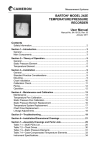
BARTON® MODEL J8A
TEMPERATURE/PRESSURE
RECORDER
User Manual
Manual No. 9A-15165001, Rev. 05
January 2011
Contents
Section 1—Introduction.................................................................................. 3
General.......................................................................................................... 3
Main Components.......................................................................................... 3
Section 2—Theory of Operation..................................................................... 5
General.......................................................................................................... 5
Static Pressure Element................................................................................ 5
Temperature Element.................................................................................... 6
Section 3—Installation ................................................................................... 9
General.......................................................................................................... 9
Mounting........................................................................................................ 9
Chart Installation.......................................................................................... 10
Calibration Check.........................................................................................11
Piping........................................................................................................... 12
Operation..................................................................................................... 12
Section 4—Maintenance and Calibration.................................................... 13
Maintenance................................................................................................ 13
Temperature Pen Calibration....................................................................... 13
Static Pressure Pen Calibration................................................................... 14
Static Pressure Element Replacement........................................................ 16
Temperature System Replacement............................................................. 16
Chart Drive Replacement............................................................................ 17
Linkage Adjustments.................................................................................... 17
Section 5—Troubleshooting......................................................................... 19
Section 6—Installation/Dimensional Drawings.......................................... 21
Section 7—Assembly Drawings and Parts Lists........................................ 25
Table 7.1—J8A Parts List............................................................................. 25
Table 7.2—Chart Drives............................................................................... 29
Table 7.3—Static Pressure Elements.......................................................... 30
Table 7.4—Case-Compensated Temperature Elements.............................. 32
Table 7.5—Fully Compensated Temperature Elements............................... 32
Instrument Specifications............................................................................. 33
Safety Information
Before installing this instrument, become familiar with the installation instructions in Section 3.
!
WARNING: This symbol identifies information about practices or circumstances that can lead to personal injury or death, property damage, or
economic loss.
CAUTION: Indicates actions or procedures which if not performed correctly
may lead to personal injury or incorrect function of the instrument
or connected equipment.
IMPORTANT: Indicates actions or procedures which may affect instrument operation or
may lead to an instrument response that is not planned.
J8A Temperature/Pressure Recorder
Section 1
Section 1—Introduction
General
The Barton Model J8A Temperature and Pressure Recorder is a versatile and
rugged instrument designed for general temperature and pressure applications. It records monitored temperature and pressure on an 8-inch diameter
chart. Up to four elements may be used in any combination to operate up to
four individual recording pens.
Main Components
Static Pressure Systems
The static pressure system consists of a helical bourdon tube connected
through tubing to system piping. The static pressure element measures the
static pressure in a piping system for 0-30 inches of mercury vacuum to
0-30,000 psi. For a list of elements and ranges, see Table 7.3—Static Pressure
Elements on page 30.
Thermal Systems
The thermal systems consist of a spiral bourdon tube, a capillary, and a bulb.
All parts are made of stainless steel. The bulb is fitted with a bendable extension, and the capillary is protected with stainless steel armor.
Recording Mechanism
The recording mechanism is a linkage and pen system that permanently
records data. It converts mechanical inputs from the pressure and temperature
elements to link lines on a revolving chart. All operative parts of the recorder
mechanism are made of stainless steel for a longer field life. The pen mount
is exceptionally rugged. All lines are adjustable. Screw adjustments for zero,
range, and linearity assure fast and accurate calibration.
Chart Drive
A variety of chart drives are available. Both electrical and spring-wound chart
drives fit a wide variety of chart speeds and time intervals that reduce maintenance time (See Section 5—Troubleshooting on page 19). All chart drives are
interchangeable and fitted with a recorder hub clip that features a simple yet
positive method of locking the chart in place. Explosion-proof electrical chart
drives are available.
3
Section 1
J8A Temperature/Pressure Recorder
Case
The J8A is housed in an aluminum case with a hinged door providing access
for chart changes and calibration adjustment. The case is finished in a black,
polyurethane electrostatic powder paint that is highly resistant to weathering, scratches, marring, and industrial fumes. The Model J8A connects to the
system or transmitter through fittings in the bottom of the case.
4
J8A Temperature/Pressure Recorder
Section 2
Section 2—Theory of Operation
General
Pressure and temperature elements in the J8A are connected by tubing or pipe
to measure system pressure and system temperature (Figure 2.1).
The capillary tubes from the static pressure element connect directly to the
piping system and are filled with the process system fluid. The thermal system
is Class V mecury filled system. See Instrument Specifications on page 33 for
details.
A chart drive mechanism turns the chart at a selected speed. The chart may
be either an electrical motor or a mechanical, spring-wound type motor (see
Table 7.2—Chart Drives on page 29).
Static Pressure Element
The sensor element, a bourdon tube, consists of a slightly flattened crosssection of tubing coiled into a helix or flat spiral. The outer end of the tubing
is sealed and attaches to a drive arm (see lever arm assembly diagram). The
open end of the tubing at the base connects to the tubing. The tubing connection attaches to the tubing of the static pressure connection on the back of
the recorder case. The static pressure connection connects the static pressure
element to the system piping.
Pressure Element
(Bourdon Tube)
Figure 2.1—J8A recorder components
5
Section 2
J8A Temperature/Pressure Recorder
Static pressure introduced through the tubing into the static pressure element
causes the spiral or helix to unwind. Conversely, a reduction of pressure
within the tubing causes the element to wind up more tightly. This motion
is transmitted through the lever arm assembly and its intermediate linkage
to the pen shaft, which controls the movement of the recorder pen. The pen
transcribes the motion onto a rotating chart to permanently record changes in
static pressure in the process system.
Temperature Element
The thermal system senses temperature changes, using the thermal expansion
principle. Temperature changes cause thermal expansion and contraction of
mercury in the bulb. When heated mercury expands, it increases in volume,
causing the bourdon tube to exert mechanical force. The bourdon tube movement is transmitted through mechanical linkage to a recording pen (Figure
2.2—Temperature element on page 7).
Thermal Bulb
The thermal bulb acts as the sensing element. Its physical and dimensional
characteristics determine response time of the system. Large surface area to
volume, minimum wall thickness, and high heat conductivity are desirable for
high speed temperature response. The metal used in thermal bulb fabrication
should have a minimum coefficient of expansion and low specific heat factor
— stainless steel is used in the Model J8A thermal bulb.
Capillary Tubing
The capillary tubing provides a thermal seal between the temperature bulb
and bourdon tube. The tubing, fabricated from thick-walled stainless steel,
minimizes the internal volume for mercury. The capillary is provided with
1/4-inch spiral armor to assure a strong and pliable transmission line between
the primary element and the secondary mechanism (bourdon tube).
Filling Fluid
Mercury is used as the filling fluid, because of its high energy generation per
unit of temperature change, wide temperature ranges, and relatively low effect
due to ambient temperature variations. Consult your nearest Cameron representative for information on other filling fluids.
Secondary Mechanism
The measuring element is a precision-wound stainless steel bourdon tube,
which converts the volumetric expansion and contraction of the mercury-fill
to an angular output of 17 degrees nominal for the full temperature range.
6
J8A Temperature/Pressure Recorder
Section 2
Figure 2.2—Temperature element
7
Section 2
8
J8A Temperature/Pressure Recorder
J8A Temperature/Pressure Recorder Section 3
Section 3—Installation
General
The instrument should be inspected at time of unpacking to detect any damage that may have occurred during shipment.
The following practices should be observed upon installation:
Distances — The distances between the temperature bulb and the recorder
case should be minimized. Maximum allowable distances are:
VA (fully compensated system): 100 feet
VB (case compensated system): 20 feet
Elevation — Maximum elevation of the temperature bulb with respect to the
recorder must not exceed 30 feet. The percent of zero shift can be calibrated
by the following:
Percent Zero Shift = 5 X ± Elevation (feet)
Span (Degree Fahrenheit)
Process Temperature — The normal operating temperature ranges for Class V
systems are listed in the Specifications list on page 33. The maximum (momentary) overrange limit is 20% of the total temperature range, while the
(momentary) underrange temperature limit of a properly pre-loaded system is
-50°F (-45°C).
Vibration — Vibration can be minimized by mounting the instrument on a
secure support.
Mounting
IMPORTANT: The instrument should be mounted as level as possible. Limit drill
penetration and remove chips. Temperature bulb capillary must precede
the recorder case through the panel cutout. Do not apply wrench or bar
pressure to the recorder case, when using a thread mount.
Flush or Panel Mounting
To use a flush or panel mount, perform the following steps:
1. Cut opening in panel to the dimensions shown in Section 6, Outline
Dimension Drawings.
2. Drill out pilot holes located on top and bottom of case. Use a
No. F drillbit (0.257 in.) and a 5/16 in.-18 tap as required.
3. Attach two flush mounting brackets to bottom of case using the enclosed
self-tapping screws.
9
Section 3
J8A Temperature/Pressure Recorder
4. Pass instrument through the panel cutout.
5. Attach remaining flush mounting bracket and install panel mounting
screws.
Pipe Mounting
To mount the recorder to a 2-in. pipe, perform the following steps:
1. Place a suitable length of 2-inch pipe into a well-secured floor or wall
flange; or if preferred, attach the 2-inch pipe to existing pipe with a
saddle that is fitted with a 2-inch pipe.
2. Attach the recorder to the pipe, orient the instrument, and tighten retaining screws.
Bulb Mounting
IMPORTANT—When locating the thermal bulb within a furnace, tank, line, etc., avoid
dead spots where fluid circulation is sluggish and temperature is not responsive. Elevation of the temperature bulb, with respect to the recorder,
will cause a slight zero shift.
To install the temperature element, perform the following steps. Refer to
Figure 2.2—Temperature element on page 7 as needed.
1. If the temperature system is furnished with a thermal well, thread the
thermal well into a 3/4-inch NPT threaded connection and secure with a
1-1/8-inch wrench. If no thermal well is used, proceed with step 3.
2. If a thermal well is being used, insert the temperature bulb into the thermal well to its full depths.
3. If no thermal well is being used, insert the bulb to the desired depth.
4. Secure the gland nut into the thermal well or existing 1/2-inch NPT connection with a 7/8-inch wrench.
5. With the bulb properly installed, secure the packing nut into the gland
nut.
Adjust the zero at the recorder to compensate for zero shift due to elevation.
See Temperature Pen Calibration on page 13 for the adjustment procedure.
Chart Installation
Perform the following steps to install the chart:
1.
2.
3.
4.
10
Open the recorder door.
Release the chart lock (located on the chart drive hub).
Raise the pen lifter arm.
Slide the chart between the pen(s) and the chart plate. Insert the chart in
the chart guides in the chart plate, and locate the hole in the chart onto
the chart hub. Place the pressure chart onto the chart hub.
J8A Temperature/Pressure Recorder Section 3
5. Lower the pen lifter arm and position the chart to place the pen(s) on the
desired chart time line.
6. Secure the chart in place with the chart hub lock.
Calibration Check
Pressure System
Check the calibration of the pressure system prior to placing the recorder into
service. Refer to the illustration and photo on the next page.
1. Connect the instrument into the calibration setup as shown on next page.
2. Apply zero pressure and adjust the pen to chart zero (zero adjust screw).
3. Apply 100% pressure. Verify that the pen moves across scale to the 100%
pressure indication.
4. Apply 50% pressure. Verify that the pen indicates 50% pressure on the
chart.
5. If the pen does not accurately indicate the pressure being applied, further
adjustments are necessary; perform the calibration procedure outlined in
Static Pressure Pen Calibration on page 14.
Figure 3.1—Pressure system calibration
Temperature System
All instruments are calibrated at the factory and normally do not require more
than a check before startup. The Model J8A has been calibrated at 0, 25, 50,
75, and 100% of full temperature range and checked for proper overtravel.
Because of the extensive procedure and elaborate test stand requirements
needed to simulate operating conditions, it is recommended that only a zero
11
Section 3
J8A Temperature/Pressure Recorder
check be performed. If the temperature system appears to be out of calibration, a complete calibration should be performed as outlined in Temperature
Pen Calibration on page 13.
Piping
Connect the pressure element to the system pressure using tubing or pipe.
The pressure connection on the outside of the recorder case is 1/4-inch NPT,
female.
Operation
To place the instrument into operation, proceed as follows:
1. Turn on the drive. Verify that the pen has ink and is in contact with chart.
2. Turn on the pressure to the recorder.
To remove the instrument from service:
1. Turn off the pressure to the recorder.
2. Turn off the chart drive.
3. Lift the pen from the chart.
12
J8A Temperature/Pressure Recorder
Section 4
Section 4—Maintenance and Calibration
Maintenance
Generally, Barton recorders require no maintenance other than replacement of
the chart, replacement of pens, winding of the spring-wound chart drives, and
occasional calibration. In addition, the operator should periodically check the
door seal for wear and the pressure fittings for tightness. See Table 4.1 for a
list of tools required for routine maintenance.
Table 4.1—Required Tools
Tool
Purpose
1/8-inch open-end wrench
Calibration adjustment (zero adjust)
5/64-inch Allen wrench
Calibration adjustment
5/64-inch open-end wrench
Capillary mounting nut
1-1/8-inch open-end wrench
Thermal well
7/8-inch open-end wrench
Gland nut
3/4-inch open-end wrench
Packing nut
Phillips screwdriver
Adjustments
Periodic Maintenance
Periodically inspect and clean the thermal well. In services where the temperature bulb or thermal well is in contact with semisolids, sludge build up can
appreciably affect the heat conductivity of the sensing element. Inspect and
clean the temperature bulb or well in the following manner:
1. Carefully remove the temperature bulb from the thermal well by loosening the packing nut and slipping it back on the bulb extension. Loosen
the jam nut and remove the temperature bulb.
2. Remove the thermal well from the socket.
3. With a fine grade steel wool, remove excess residue from the temperature
bulb and thermal well.
4. Examine the capillary tubing for damage or kinking.
Temperature Pen Calibration
IMPORTANT: Verify that all linkage is free. Adjust range arm and drive arm at precisely
the same distance back of the case. Adjust the lever arm and pen zero
adjust screws to their midpoints all 90° midscale linkage angles must be
measured.
Calibrate the temperature pen after replacing the thermal element. The complete calibration procedure is as follows:
1. Apply 50% of the total temperature range.
13
Section 4
J8A Temperature/Pressure Recorder
2. Adjust the drive arm and the driven arms to approximately 90° angles
with the intermediate arms.
3. Reduce temperature to zero or starting point of the temperature range.
Reset zero with zero adjusting screw.
4. Apply 100% temperature and set the pen to full scale by turning the
adjusting screw.
5. Reduce temperature to zero or starting point and check zero reading. If
pen is correct, proceed with step 7.
6. If zero adjustment is required, repeat steps 3 through 5 until desired accuracy is maintained.
7. Apply 50% temperature and observe pen indication.
a. If pen indicates high or low, adjust drive link to make a correction
approximately 40 times the error — in the direction of the error.
b. Reset the pen to the 50% line by slipping the pen at the range arm
pivot point.
c. Repeat this step (7), as necessary.
8. Reduce temperature to zero or starting point and reset zero.
a. If zero offset is minor, reset zero with zero adjust screw.
b. If zero offset is major, reset zero by loosening bourdon mounting
screws and rotate to approximately zero. Set precise zero w/zero
adjust screw.
9. Repeat steps 4 through 8 until desired accuracy is maintained.
Static Pressure Pen Calibration
To calibrate the static pressure pen and linkage, proceed as follows:
1. Adjust the static range arm and drive arm at precisely the same distance
from the back of the case.
2. Place static drive link in the fourth hole from the pen shaft of the range
arm.
3. Adjust static pressure linkage to form 90° angles between the drive link
(see above illustration) and pivot points of the associated linkage, as follows:
a. Apply 50% static pressure, center thumb nut on the drive arm, and
arrange static linkage as shown in illustration above.
b. Set a 90° angle between drive arm & link. Tighten clamp block
screw.
c. Vary the length of link to get a 90° angle between range arm and
link.
d. Slip the range arm on pen shaft to 50% on chart.
4. Release pressure and reset the pen to zero indication, using pen zero
adjust screw for fine adjustment (10% or less). For major adjustments
(more than 10%), loosen range arm lock screw and slip the pen to zero on
chart and retighten lock screw.
14
J8A Temperature/Pressure Recorder
Section 4
Figure 4.1—Static pressure pen calibration
IMPORTANT—It may be necessary to raise or lower the pivot point of the drive link on
the range arm, as in step 3. If counterclockwise movement of thumb nut
(step 5) does not increase span sufficiently, move the pivot pin up to next
pivot hole; if clockwise, movement of the thumb nut does not decrease
span sufficiently, move pivot pin down to the next pivot hole.
5. Apply 100% pressure and observe the pen. Make the necessary adjustments by turning the drive arm thumb nut counterclockwise if the pen
is slightly underranged and clockwise if the pen is slightly overranged.
Repeat zero and 100% adjustment until calibration at these two points is
achieved.
6. Apply 50% pressure and observe pen indication.
a. If pen indicates high or low, adjust drive link to make a correction
approximately 40 times the error — in the direction of the error.
b. Reset the pen to the 50% line by slipping the pen shaft at the range
arm pivot point.
c. Repeat this step (7), as necessary.
15
Section 4
J8A Temperature/Pressure Recorder
8. Release pressure and reset the pen to zero indication, using pen zero
adjust screw for precise adjustment.
9. Repeat steps 4 through 8 until calibration of zero, linearity, and span (0%,
50%, and 100% indication) is achieved.
10. Assure that range arm lock screws, thumb nut lock screw, and link screws
are tight.
11. Unlock the recorder hub clip and remove temporary calibration chart.
12. Replace the chart plate by sliding it into the chart plate retainer brackets
and engaging each side into the chart plate latches.
Static Pressure Element Replacement
If the static pressure element needs replacement, proceed as follows:
1. Close all valves and turn off the power switch to the recorder.
2. Separate the drive link arm by opening the link table and disengaging the
pivot pin from the clamp.
3. Loosen the clamp block screw on the lever arm assembly and separate
the drive arm from the static pressure element shaft.
4. Disconnect the tubing from the static pressure element at the tubing connection (refer to Figure 4.1—Static pressure pen calibration on page 15).
5. Remove the mounting screws from the static pressure element and discard the damaged element.
6. Install the new element, using the old mounting screws.
7. Connect tubing to the element at the tubing connection.
8. Assemble the lever arm assembly onto the static pressure element shaft;
do not tighten the clamp block screw yet.
9. Connect the drive link to the drive arm by engaging the pivot pin and
locking the link tab into place.
10. Align the static pressure linkage (range arm, drive link, and drive arm) so
that it lies in the same plane without binding or bending.
11. Tighten clamp block screw.
12. Calibrate in accordance with the procedure outlined in Static Pressure
Pen Calibration on page 14.
Temperature System Replacement
Perform the following steps to replace the temperature system:
1. Loosen packing and gland nuts. Remove temp. bulb from thermal well.
2. Loosen capillary retaining nut and slip back on tubing.
3. Remove four temperature element connection screws located on the back
side of the recorder case where capillary tubing enters the case.
4. Remove union bracket by slipping the bracket onto the capillary connecting tubing. Slip the bracket through the slit provided.
5. Remove the intermediate drive arm from bourdon drive extension.
16
J8A Temperature/Pressure Recorder
Section 4
6. Remove the bourdon mounting screws and remove complete temperature
unit by feeding the capillary through the entry hole provided.
7. To install new element, reverse above procedure.
8. Calibrate in accordance with procedures outlined in Temperature Pen
Calibration on page 13.
Chart Drive Replacement
To replace the chart drive, proceed as follows:
1.
2.
3.
4.
Release the pressure to the recorder.
Turn off the chart drive.
Raise the pen lifter and remove the chart and chart plate.
Remove the chart drive mounting screws and remove the chart drive
from the recorder case.
5. Position the new chart drive at the back of the recorder case and attach
with mounting screws.
6. Replace the chart plate and the chart. Lower the pen to the recording
position.
7. Check the time line on first pen from chart, zero, and span elements.
Linkage Adjustments
Tightening the range arm and drive arm lock screws fingertight is often not
tight enough; tightening them more than a full turn will often break them.
To correctly tighten linkage screws, perform the following steps. Refer to
Figure 4.2 - Linkage adjustments on page 18 as needed.
1. Tighten the lock screw until snug.
2. Hold the drive arm at the clamp block by hand or with a 1/4-inch open
end wrench. If a wrench is used, place it between the torque tube shaft
or bearing. (In the case of the range arm lock screw, place the wrench
between the pen shaft and lock screw.)
3. Tighten the lock screw 1/3 to 1/2 turn beyond snug.
4. Test for tightness by moving the free end of drive arm approximately
1/2-inch in either direction. The drive arm should spring back with no
yielding.
17
Section 4
J8A Temperature/Pressure Recorder
Figure 4.2 - Linkage adjustments
18
J8A Temperature/Pressure Recorder Section 5
Section 5—Troubleshooting
Table 5.1—Troubleshooting Guide
Problem
Source
Probable Cause
Corrective Action
Low or No Indication
Excessive residue
formation on temperature bulb
Heating conductivity of temperature bulb is
impaired
Remove from
service and clean
element
Mechanism
Loose links or
movements
Tighten or replace
Out of calibration
Recalibrate
Corrosion or dirt
in mechanism
Clean or replace
Pen arm loose
Tighten
Loss of fill
Capillary cracked,
kinked, or broken
Replace temperature bulb
Element
Defective element
Replace element
Tubing
Loose connection
Tighten connections
Tubing plugged
Clear tubing
Pen arm
Pen arm bent
Straighten or
replace pen arm
High Indication
Mechanism
Loose links or
movements
Tighten or replace
Out of calibration
Recalibrate
Erratic Indication
Mounting
Excessive vibration
Secure the means
of mounting
Mechanism
Linkage dragging
or dirty
Adjust or clean
Excessive pen
pressure on chart
Adjust
Fuse
Fuse Blown
Check and replace
fuse
Chart Drive
Electric drive not
turned on
Turn on chart drive
Clock motor not
wound
Wind chart drive
No Chart Rotation
Wrong Chart Speed
Defective drive
Replace drive
Chart Hub Lock
Lock not latched
Latch hub lock
Chart Drive
Wrong chart drive
Replace with proper
chart drive
19
Section 5
20
J8A Temperature/Pressure Recorder
J8A Temperature/Pressure Recorder Section 6
Section 6—Installation/Dimensional Drawings
10.44 [266]
13.69 [348]
Figure 6.1—J8A mounting options
21
Section 6
J8A Temperature/Pressure Recorder
Figure 6.2—J8A mounting options (cont'd)
22
J8A Temperature/Pressure Recorder Section 6
Figure 6.3—Typical thermal well installation
23
Section 6
J8A Temperature/Pressure Recorder
Figure 6.4—Typical thermal well installation (cont'd)
24
J8A Temperature/Pressure Recorder
Section 7
Section 7—Assembly Drawings and Parts Lists
Figure 7.1— J8A assembly
!
WARNING: Use only spare parts identified in this manual. Cameron bears
no legal responsibility for the performance of a product that has been
serviced or repaired with parts that are not authorized by Cameron.
Table 7.1—J8A Parts List
Item
1
Part No.
9A-5600185
Description
Door Assembly, Recorder
Qty/Unit
1
2
9A-5600180
Case, Recorder
1
3
9A-4828530
Pen Lifter Assembly (New Style)
1*
25
Section 7
J8A Temperature/Pressure Recorder
Table 7.1—J8A Parts List
Item
4
Part No.
9A-4827956
Description
Qty/Unit
Latch, Door (Sub-Assy)
1
5
9A-4861300
Riser, Chart Plate
4
7
9A-4527858
Bushing, Door Stop
1
8
9A-0238-1019C
Screw, CAP 1/4-20x5/8 (Not Shown)
(Used w/Riser)
1
9
9A-5600115
Hinge, Door
10
9A-0238-0019C
Entrance Plate Gasket (Static Line)
1**
12
9A-5600135
Connection, Static Pressure
1**
14
14A
9A-4547856
1
Pen Mount Assembly
1
2 Pen
1
14B
9A-4547858
1 Pen (Not Shown)
15
9A-0238-0015B
Link Assembly (First or Second Pen)
1**
17
9A-0238-0006B
Shaft, Pen Arm 1st
1
18
9A-0238-0007B
Shaft, Pen Arm 2nd
1
21
9A-0202-0034B
Pen Shaft Arm Assy. (90 Degree Range
Arm)
1**
23
9A-0238-0031B
Static Drive Arm (Alternate P/N 9A-400-754)
1**
24
9A-80-36-1670-01
Arm, Pen (First from Chart)
1**
25
9A-80-36-1670-01
Arm, Pen (Second from Chart)
1**
28***
Disposable Pen,
1st from Chart,
6 per pkg
26
A/R
Blue, Scanner,
High Temp.
9A-BDP-S-1-BL-S-6
Blue Scanner, Low
Temp.
9A-BDP-S-1-BL-L-6
Black, Scanner,
High Temp.
9A-BDP-S-1-BK-S-6
Black Scanner,
Low Temp
9A-BDP-S-1-BK-L-6
Blue, Integrator,
High Temp.
9A-BDP-I-1-BL-S-6
Blue Integrator,
Low Temp.
9A-BDP-I-1-BL-L-6
Black, Integrator,
High Temp.
9A-BDP-I-1-BK-S-6
Black Integrator,
Low Temp.
9A-BDP-I-1-BK-L-6
J8A Temperature/Pressure Recorder
Section 7
Table 7.1—J8A Parts List
Item
Part No.
Description
Blue, Universal,
High Temp. ****
9A-BDP-U-1-BL-S-6
Blue Universal,
Low Temp. ****
9A-BDP-U-1-BL-L-6
Black, Universal,
High Temp. ****
9A-BDP-U-1-BK-S-6
Black Universal,
Low Temp. ****
9A-BDP-U-1-BK-L-6
Qty/Unit
High Temp = +20° to +120° F (-7° to 48°C);
Low Temp = -40° to +90° F (-40° to 32° C)
29***
Disposable Pen,
2nd from Chart,
6 per pkg
A/R
Red, Scanner,
High Temp.
9A-BDP-S-2-RD-S-6
Red Scanner, Low
Temp.
9A-BDP-S-2-RD-L-6
Red, Integrator,
High Temp.
9A-BDP-I-2-RD-S-6
Red Integrator,
Low Temp
9A-BDP-I-2-RD-L-6
Red, Universal,
High Temp. ***
9A-BDP-U-2-RD-S-6
Red Universal,
Low Temp ***
9A-BDP-U-2-RD-L-6
High Temp = +20° to +120° F (-7° to 48°C);
Low Temp = -40° to +90° F (-40° to +32°C)
30***
Disposable Pen,
3rd from Chart,
6 per pkg
(Not shown)
A/R
Green, Scanner,
High Temp.
9A-BDP-S-3-GN-S-6
Green Scanner,
Low Temp.
9A-BDP-S-3-GN-L-6
Green, Integrator,
High Temp.
9A-BDP-I-3-GN-S-6
Green Integrator,
Low Temp.
9A-BDP-I-3-GN-L-6
Green, Universal,
High Temp. ****
9A-BDP-U-3-GN-S-6
27
Section 7
J8A Temperature/Pressure Recorder
Table 7.1—J8A Parts List
Item
Part No.
Green Universal,
Low Temp ****
Description
Qty/Unit
9A-BDP-U-3-GN-L-6
High Temp = +20° to +120° F (-7° to 48°C);
Low Temp = -40° to +90° F (-40° to 32°C)
31***
A/R
Disposable Pen,
4th from Chart,
6 per pkg
(Not shown)
Purple, Universal,
High Temp. ****
9A-BDP-U-4-PL-S-6
Purple Universal,
Low Temp. ****
9A-BDP-U-4-PL-L-6
High Temp = +20° to +120° F (-7° to 48°C);
Low Temp = -40° to +90° F (-40° to +32°C)
32
9A-0238-1026G
Plate, Data Recorder
33
9A-6531018
Door Stop Assembly
1
1
34
9A-0238-0029B
Door Latch Assembly Hook
1
35
9A-5600141
Gasket, Cover Glass
1
36
9A-5600091
Cover, Glass
1
37
9A-5600095
Clip, Cover Glass
4
38
9A-7927909
Handle
1
39
9A-4528372
Bushing, Door Handle (Not Shown)
1
42
9A-5600140
Gasket, Recorder Door
1
43
9A-5600089
Plate, Chart (Not Shown)
1
44
9A-0238-0007C
Riser, Chart Drive
3
45
See Table 7.2
Drive, Chart
1
46
See Table 7.2
Hub, Chart
1
51
See Tables 7.4, 7.5 Element, Temperature
52
See Table 7.3
Element, Pressure
57
9A-0003-0036K
Washer, Lock, No. 8
2
58
9A-0938-0001J
Screw, Round Head, 6-32 x 1/4
26
59
9A-0114-0031J
Screw, Fil. Head, 10-32 x 1/2
2
60
9A-0111-0085J
Screw, Round Head, 10-32 x 5/16, Element
Mounting (Pressure)
2***
61
9A-0111-0085J
Screw, Round Head, 10-32 x 5/16, Element
Mounting (Temperature)
2**
62
9A-0946-0002J
Screw, Self-tapping, 10-24 x 1/4, Pressure
Connections
4**
63
9A-0114-0017C
Screw, 6-40 x 1/4
28
3
J8A Temperature/Pressure Recorder
Section 7
Table 7.1—J8A Parts List
Item
Part No.
Description
Qty/Unit
66
9A-0111-0086J
Screw, Round Head, 10-32 x 1/4 (Not
Shown)
1
67
9A-0111-0085J
Screw, Round Head, 10-32 x 5/16 (Not
Shown)
6
68
9A-0003-0047K
Washer, Flat, No. 10
2
69
9A-0003-0033K
Washer, Shakeproof, No. 10
3
70
9A-0320-0010J
Set Screw, Handle, 8-32 x 1/4 (Not Shown)
1
71
9A-0003-1064K
Washer, Flat
2
75
Mounting Bracket Assy., Slip-on (Not
Shown)
75A
9A-0199-1514C
Bracket Assembly, Recorder-Slip-on
1
75B
9A-0240-0009J
Screw, Flat Head, 1/4-20 x 1/2
4
76
Mounting Bracket Assy., Threaded (Not
Shown)
76A
9A-0199-1190B
Bracket, Threaded
1
76B
9A-0240-0009J
Screw, Flat Head, 1/4-20 x 1/2
4
77
Mounting Bracket Assy., Panel (Not Shown)
77A
9A-0202-1004B
Panel Mounting Kit (Not Shown)
1
77B
9A-0238-0068C
Bracket, Panel Mounting
3
77C
9A-0238-0069C
Pad, Pressure
3
77D
9A-0238-0070C
Panel, Mounting Screw, 5/16-18
3
77E
9A-0911-0004J
Screw, 1/4-20 x 5/8
6
77F
9A-0500-0033J
Nut, Hex., 5/16-18
6
77G
9A-0240-0009J
Screw, Flat Head, 1/4-20 x 1/2
4
*Old Style Part No. 9A-5600120
**Multiply by number of pens used.
***Recommended spare parts
**** Universal type pens are required for (4) four pen meters
A/R As Required
Table 7.2—Chart Drives
Part No.
Description
Mechanical (Spring Wound)
9A-0042-0015T
24 Hour/9 Day
9A-0042-0016T
7 Day
9A-0042-0017T
24 Hour/7 Day
9A-0042-1008T
24 Hour/7 Day
9A-0042-0030T
8 Day
29
Section 7
J8A Temperature/Pressure Recorder
Table 7.2—Chart Drives
Part No.
Description
Mechanical (Spring Wound)
9A-0042-0031T
24 Hour/8 Day
9A-0042-1004T
31 Day
9A-0042-1003T
2 Hour/8 Hour
9A-0042-0024T
4 Hour
9A-0042-1007T
1 Hour/15 Minute
9A-0042-0020T
96 Minute/24 Hour
9A-0042-1009T
1 Hour/3 Hour
9A-0042-1015T
24 hour
Battery Driven (1.5 VDC - C Cell Alkaline)
9A-0043-1002T
11 Selectable Speeds
9A-0043-1003T
11 Selectable Speeds (Foxboro)
9A-0043-1004T
11 Selectable Speeds (CSA Approved)
9A-0043-1005T
12 Selectable Speeds (Including 4 Hour)
9A-0043-2001T
Fast Slow Speeds
9A-0043-2002T
Fast/Slow (Foxboro)
9A-0238-0033B
One Piece Hub
Chart Drive Accessories
Hub (Used w/ 625G070)
Cap & Chain (Used w/ 725G198)
Univ Mounting Plate
Wind Key
Wind Key, Long Shank
Push/Pull Hub (Foxboro)
Table 7.3—Static Pressure Elements
Part No.
Standard Ranges
Helical Elements (316 SST; 1/8” Union Connection; Ranges in PSIG)
9A-B17SL-25
0-25
9A-B17SL-35
0-35
9A-B17SL-50
0-50
9A-B17SL-75
0-75
9A-B17SL-100
0-100
9A-B17SL-150
0-150
9A-B17SL-200
0-200
9A-B17SL-250
0-250
30
J8A Temperature/Pressure Recorder
Section 7
Table 7.3—Static Pressure Elements
Part No.
Standard Ranges
9A-B17SL-300
0-300
9A-B17SL-350
0-350
9A-B17SL-400
0-400
9A-B17SL-500
0-500
9A-B17SL-600
0-600
9A-B17SL-750
0-750
9A-B17SL-1000
0-1000
9A-B17SL-1500
0-1500
9A-B17SL-2000
0-2000
9A-B17SL-2500
0-2500
9A-B17SL-3000
0-3000
9A-B17SL-3500
0-3500
9A-B17SL-4000
0-4000
9A-B17SL-5000
0-5000
9A-B17SL-6000
0-6000
9A-B17SL-8000
0-8000
9A-B17SL-10MU
0-10,000
High Pressure (9/16-18 Aminco Process Connection)
9A-B17SL-10M
0-10,000 (W/18” Welded Connection Line) Autoclave Conn.
9A-B17SL-15M
0-15,000 (W/18” Welded Connection Line) Autoclave Conn.
9A-B17SL-20M
0-20,000 (W/18” Welded Connection Line) Autoclave Conn.
9A-B17SL-25M
0-25,000 (W/18” Welded Connection Line) Autoclave Conn.
9A-B17SL-30M
0-30,000 (W/18” Welded Connection Line) Autoclave Conn.
9A-SS44M-7-4
1/4”HP x 1/4” FNPT High Pressure Adapter
Monel
B17MK-XXXX
(“XXXX” = range in
PSIG)
Monel element. Available in ranges from 0-250 PSIG thru
0-6000 PSIG (W/18” Welded Connection Line. 1/4” FNPT
Conn.)
31
Section 7
J8A Temperature/Pressure Recorder
Table 7.4—Case-Compensated Temperature Elements
Class VB, Mercury Filled,
1/8" capillary w/armor, 11/16" diameter sensing bulb
Temp (°F)
10 ft (3 m)
15 ft (4.57 m)
20 ft (6 m)
0-100
9A-CO-100F10F9A
9A-CO-100F15F9A
9A-CO-100F20F9A
0-150
9A-CO-150F10F9A
9A-CO-150F15F9A
9A-CO-150F20F9A
0-200
9A-CO-200F10F9A
9A-CO-200F15F9A
9A-CO-200F20F9A
0-300
9A-CO-300F10F9A
9A-CO-300F15F9A
9A-CO-300F20F9A
0-500
9A-CO-500F10F9A
9A-CO-500F15F9A
9A-CO-500F20F9A
Class IB, Hydrocarbon Filled,
1/8" capillary w/armor, 3/8" diameter sensing bulb
Temp (°F)
10 ft (3 m)
15 ft (4.57 m)
20 ft (6 m)
0-100
9A-CO-100F10F7B
9A-CO-100F15F7B
9A-CO-100F20F7B
0-150
9A-CO-150F10F7B
9A-CO-150F15F7B
9A-CO-150F20F7B
0-200
9A-CO-200F10F7B
9A-CO-200F15F7B
9A-CO-200F20F7B
0-300
9A-CO-300F10F7B
9A-CO-300F15F7B
9A-CO-300F20F7B
0-500
9A-CO-500F10F7B
9A-CO-500F15F7B
9A-CO-500F20F7B
Table 7.5—Fully Compensated Temperature Elements
Class VA, Fully Compensated, Mercury Filled,
1/8" capillary w/armor, 11/16" diameter sensing bulb
Temp (°F)
20 ft (6 m)
25 ft (7.6 m)
30 ft (9.1 m)
0-100
9A-F0-100F20F8A
9A-F0-100F25F8A
9A-F0-100F30F8A
0-150
9A-F0-150F20F8A
9A-F0-150F25F8A
9A-F0-150F30F8A
0-200
9A-F0-200F20F8A
9A-F0-200F25F8A
9A-F0-200F30F8A
0-300
9A-F0-300F20F8A
9A-F0-300F25F8A
9A-F0-300F30F8A
0-500
9A-F0-500F20F8A
9A-F0-500F25F8A
9A-F0-500F30F8A
Class IA, Fully Compensated, Hydrocarbon Filled,
1/8" capillary w/armor, 3/8" diameter sensing bulb
Temp (°F)
32
20 ft (6 m)
25 ft (7.6 m)
30 ft (9.1 m)
0-100
9A-F0-100F20F6B
9A-F0-100F25F6B
9A-F0-100F30F6B
0-150
9A-F0-150F20F6B
9A-F0-150F25F6B
9A-F0-150F30F6B
0-200
9A-F0-200F20F6B
9A-F0-200F25F6B
9A-F0-200F30F6B
0-300
9A-F0-300F20F6B
9A-F0-300F25F6B
9A-F0-300F30F6B
0-500
9A-F0-500F20F6B
9A-F0-500F25F6B
9A-F0-500F30F6B
J8A Temperature/Pressure Recorder
Section 7
Instrument Specifications
General:
Case����������������������������������������������� Die-cast aluminum, black polyurethane electrostatic
powder paint, hinged glass-front door, neoprene
gasket seal
Chart Drive������������������������������������� Spring-wound or battery-operated
Chart Size��������������������������������������� 8-inch diameter
Chart Rotation�������������������������������� 60 minutes to 31 days
Number of Pens����������������������������� 1 to 4 (one for each element)
Pen Style���������������������������������������� Disposable
Element:
Type������������������������������������������������ Pressure: Helical (bourdon);
Temperature: Helical (bourdon), Class V
mercury filled
Number������������������������������������������� 1 to 4 (any combination)
Range��������������������������������������������� Helical: (0-30" Hg vacuum to 0-30,000 psi)
Accuracy����������������������������������������� Static Pressure: ±1% of full scale
Temperature: ±1% of full scale
Material������������������������������������������� Helical: Stainless Steel and K-Monel
Class V Thermal System:
(Ambient Temperature Compensated)
Class VA����������������������������������������� Fully compensated
-40° to 600°F (-40° to 315°C)
Class VB����������������������������������������� Case compensated
-40° to 600°F (-40° to 315°C)
Class I Thermal System: (Ambient Temperature Compensated):
Class IA������������������������������������������ Fully compensated
Class IB������������������������������������������ Case compensated
Class I Range Limits:
Ethyl-Benzene (EB)������������������������ -125° to 350°F (-87° to 177°C)
Kerosene (KER)����������������������������� -20° to 500°F (-29° to 260°C)
Alcohol (ALC)��������������������������������� -200° to 150°F (-129° to 66°C)
33
Section 7
34
J8A Temperature/Pressure Recorder
Product Warranty
A.
Warranty
Cameron International Corporation ("Cameron") warrants that at the time of shipment, the
products manufactured by Cameron and sold hereunder will be free from defects in material and workmanship, and will conform to the specifications furnished by or approved by
Cameron.
B.
Warranty Adjustment
1. If any defect within this warranty appears, Buyer shall notify Cameron immediately
2. Cameron agrees to repair or furnish a replacement for, but not install, any product
which within one (1) year from the date of shipment by Cameron shall, upon test and
examination by Cameron, prove defective within the above warranty.
3. No product will be accepted for return or replacement without the written authorization of Cameron. Upon such authorization, and in accordance with instructions by
Cameron, the product will be returned shipping charges prepaid by Buyer. Replacements made under this warranty will be shipped prepaid.
C. Exclusions from Warranty
1. THE FOREGOING WARRANTY IS IN LIEU OF AND EXCLUDES ALL OTHER
EXPRESSED OR IMPLIED WARRANTIES OF MERCHANTABILITY, OR FITNESS FOR A PARTICULAR PURPOSE, OR OTHERWISE.
2. Components manufactured by any supplier other than Cameron shall bear only the
warranty made by the manufacturer of that product, and Cameron assumes no responsibility for the performance or reliability of the unit as a whole.
3. "In no event shall Cameron be liable for indirect, incidental, or consequential damages nor shall the liability of Cameron arising in connection with any products sold
hereunder (whether such liability arises from a claim based on contract, warranty, tort,
or otherwise) exceed the actual amount paid by Buyer to Cameron for the products
delivered hereunder."
4. The warranty does not extend to any product manufactured by Cameron which has
been subjected to misuse, neglect, accident, improper installation or to use in violation
of instructions furnished by Cameron.
5. The warranty does not extend to or apply to any unit which has been repaired or altered at any place other than at Cameron's factory or service locations by persons not
expressly approved by Cameron.
Product Brand
Barton® is a registered trademark of Cameron International Corporation ("Cameron").
35
+603.5569.0501
[email protected]